Norsonic nor121 User manual
Extension to
INSTRUCTION
MANUAL
SOFTWARE VERSION 4.0
Introducing:
Swept-Sine
measurement
technique
and other new features
nor121
SOUNDANALYSER


nor121
Introducing:
Swept-Sine measurement technique

Nor121 - Extension to instruction Manual March 2006 Edition
Software version 4.0
Introducing SweptSine measurement technique
Im121_5Ed1R0Eng
Norsonic is a registered trademark of Norsonic AS. All other brand
or product names are trademarks or registered trademarks of their
respective companies.
Every effort has been made to supply complete and accurate in-
formation. However, Norsonic AS assumes no responsibility for
the use of – nor for the consequential damages of the use of – this
information and/or the instrumentation described herein. Further-
more Norsonic AS assumes no responsibility for any infringement
of the intellectual property rights of third parties, wherever appli-
cable, which would result from such use.
Norsonic AS reserves the right to amend any of the information
given in this manual in order to take account of new develop-
ments.
If you wish to communicate with us, please feel welcome.
Our address is:
Norsonic AS, P.O. Box 24, N-3421 Lierskogen, Norway
Find us on the web: www.norsonic.com
Tel: +47 3285 8900
Fax: +47 3285 2208
e-mail: info@norsonic.no
Copyright © Norsonic AS 2006
All rights reserved

Instruction manual
page v
Introduction 1
General Features 3
Quicker instrument switch-off 3
Save a new default set-up 3
SMS command for date and time 3
0 dB reference selection 4
Improved modem connections 4
New weather station connection 4
Environmental mode 5
Pre-weighting of spectra 5
Noise criterions (NC, NR, RC) 6
Marker for external DC failure 8
Reference tone on recordings 8
Pure tone mode 9
Improved possibilities 9
Pre-set pure tone Standards 9
Building acoustic mode 10
Spectrum Adaptation Terms 10
Equalizer 11
General 11
Equalizer implementation characteristics 11
Using EQ with the pink noise excitation - a cookbook 12
Using EQ with the Swept-Sine excitation - a cookbook 12
Swept-Sine measurement technique 13
Building Acoustics measurements
using Swept-Sine technique 14
Introduction - What is Swept-Sine technique? 14
Benefits of using Swept-Sine 15
Principles behind the method 16
Implementation in Nor121 18
Excitation signal 18
Measurement of IRs - deconvolution 19
Setting up for Swept-Sine measurement 20
Level Setup 22
Reverberation setup 24
Rating and BGN setup 24
Correction setup 24
Making Measurements with Swept-Sine 25
Level in channel 2 and SNR display 25
What does the measured BGN and SNR mean? 27
What does the “?” displayed with level values mean? 27
Measurement of high sound insulation values 29
Technical specifications 30
Bandwidth = 1/3 Octaves 30
Bandwidth = 1/1 Octaves 30
Broadband impulse response
measurements using Swept-Sine 31
Implementation 31
Making IR Measurements - a cookbook 31
Transferring measured IR from the Instrument to a PC 32
Technical specifications 32
Contents


Instruction manual
page 1
Introduction
The measurement capabilities of the Nor121 sound level
meter depend largely on the options installed in the in-
strument. This user guide is applicable to software ver-
sion 4.0 which contains many new features like:
• Pre-weighting of spectra
• Reference tone on recordings
• 0 dB reference selection
• Quicker instrument switch-off
• Equaliser for signal generator
• Swept-Sine measurement technique
The options may be either ordered and installed in in-
struments delivered from the factory or retrofitted to ear-
lier delivered units. This manual does not describe how to
install the options. Contact the factory or your Norsonic
representative if you need more information.
For description of the sound level meter Nor121 in gen-
eral, reference should be made to the main user guide for
the instrument.

Nor121
page 2
Instruction manual
page 3
Save a new default set-up
The Nor121 contains a default set-up that will always be
loaded by turning the instrument on until a new Standard
set-up is chosen. The operator now has a choice to save
any current setting of the instrument as the future default
set-up just by selecting the field named “Save current
set-up as default” in the Set-up menu and then pressing
the Enter key. If the instrument is later turned off with the
“Save default set-up at switch-off” flag set to “No” (see
the new feature described above), then the instrument will
on subsequent switch-on start with exact the set-up previ-
ously chosen as default.
The “Save current set-up as default” feature may also
be activated using the remote control command “SDS”.
SMS command for date and time
The Nor121 will respond to SMS-messages and give the
results from both noise and weather measurements. How-
ever, it is now possible to additionally read-out the actual
date and time of the instrument’s clock simply by sending
the SMS-command “CLOCK” to the Nor121.
General Features
Quicker instrument switch-off
The Nor121 was originally designed to save the current
set-up by switch-off in order to start up again with exactly
the same set-up. However, this means that the turn-off
procedure lasts for couple of seconds. The new version
has a choice in the Setup menu that will de-activate this
feature allowing the instrument to switch-off immediately.
The consequence, however, is that the instrument may
not start up again with the same set-up that it had just
before switch-off.
In the Set-up/Standards menu, the user may save the cur-
rent set-up as a future default set-up, as well as turn off the
automatic save of current set-up at instrument switch-off.
Nor121
page 4
Improved modem connections
The Nor121 may be used for long term noise monitoring
in a system based on modem connection to the NorXfer
version 4.2 software. Earlier versions of the Nor121 occa-
sionally had some problems with the output buffer when
the modem connection was broken. This has now been
improved and the stability of such remote connections is
much better with the version 4.0 internal software.
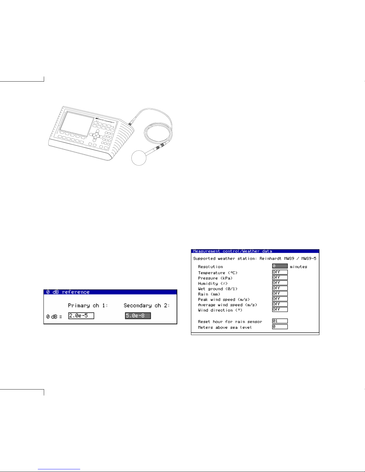
New weather station connection
The original version of the Nor121 only connected to the
Reinhard weather station type MWS9. The new version of
internal Nor121 software now additionally communicates
with the new model MWS9-5 and MWS5.
0 dB reference selection
The Nor121 has had the possibility to choose different “0
dB reference” values in order to make measurement in dB
relative to either sound or vibration units. The choices are
2.0e-5 (sound), 1.0e-6 (acceleration) and 5.0e-8 (sound
particle velocity). The “normal” value is the 2.0e-5 (i.e. 20
micro Pascal). When another reference is chosen, the dB
labels are displayed with inverse video in order to avoid
the misunderstandings with “normal” dB values.
In the new version, the selection of the “0 dB refer-
ence” value is moved from the Range/Calib menu to a
separate Range / 0 dB reference menu in order to avoid
possible misunderstanding or wrong selection by a user
that is working under pressure.
The 0 dB reference selection is now moved to a seperate
sub-menu.

Instruction manual
page 5
Environmental mode
Pre-weighting of spectra
The graphical and numerical displays of frequency spec-
tra within all the reports in the Environmental mode, may
now be viewed via a selectable A-weighting filter. This A-
preweighting feature is turned On/Off in the Set-up/Dis-
play menu.
The presence of A-pre-weighting is clearly indicated
in the various displays as all values are followed by a
“dB(A)” indication instead of the normal “dB” label.
All frequency spectrum displays in the Environmental mode may be viewed
without any pre-weighting (left) or with the new A-pre-weighting feature (right).
Nor121
page 6
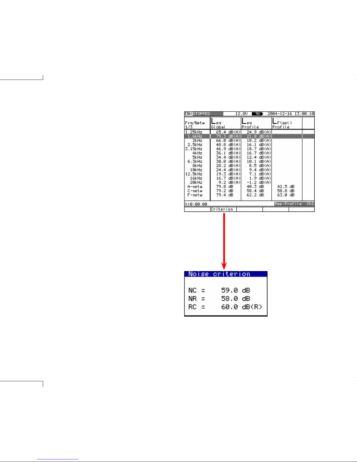
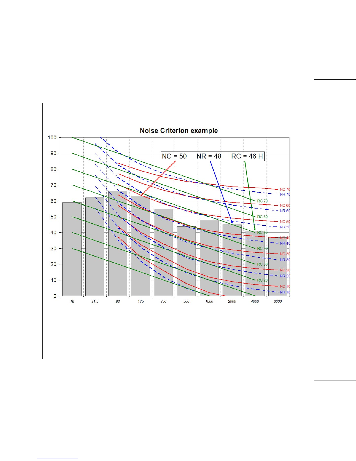
Noise criterions (NC, NR, RC)
Many applications, particularly in the heating & ventilation
industry, require the use of noise rating criteria that com-
pare the frequency spectra of the measured noise levels
against reference curves.. Version 4.0 of Nor121 provides
the standardized NC, NR and RC noise rating criteria,
and hence any spectrum measured in the Environmen-
tal mode may therefore be evaluated using these criteria.
This new feature is available from a soft key displayed
below all the level vs. frequency numerical tables with the
results displayed in a dialogue box.
These noise criteria normally require a 1/1-octave fre-
quency spectrum, however if a 1/3 –octave spectrum is
selected the Nor121 will automatically re-calculate it into
an appropriate 1/1-octave spectrum prior to noise crite-
rion evaluation.
The Noise Criterions evaluation
are calculated and presented
as a table by a push on the
Criterion softkey displayed with
the numerical frequency table of
the selected report
Instruction manual
page 7
The Noise Criterion evaluation search the highest 1/1-octave band that fits below the applicable noise
criterion lines. The evaluation is performed in 1 dB steps. 1/3-octave spectrums are re-calculated into
1/1-octave spectrums prior to evaluation.
Nor121
page 8
Marker for external DC failure
When the Nor121 instrument is used for long-term noise
monitoring powered by an external 12V supply, with the
internal battery as backup, it may be useful to know if the
external power source has powered down at any time
during a running measurement. By entering the name
“Ext DC fail” for marker no.9 the Nor121 will automatically
activate this marker each time the external DC is absent.
When the external power for the Nor121 is restored again,
the marker will be turned off. Hence, at the end of a long-
term measurement, the operator may view the absent
time periods as a marker along the level vs. time display,
or, at the PC using the NorReview post processing soft-
ware. This feature will indicate if the instrument was, for
example, powered down and moved to another location
during the measurement.
Reference tone on recordings
When the Nor121 is used to make true audio recordings of
the measured sound it is often necessary for them to be
replayed as part of either mediation or legal proceedings.
In these circumstances it is important to be able to adjust
the speaker, or headset, to the correct level in order for a
non-technical audience to appreciate the original acous-
tic environment. The new version of Nor121 has therefore
the possibility to record a reference tone at a pre-defined
level that can be used as a reference to adjust the head-
set or speaker level.
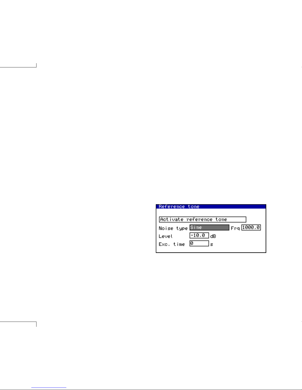
The reference tone can be recorded at the start of the
measurement, and additionally at any time during that
particular measurement. The maximum level of the refer-
ence tone is 1 V rms, but may be set to a lower level in the
RangeCal / Ref. Tone menu. The length of the reference
tone after activation may also be selected. In the same
menu the type of signal used for the reference tone may
be specified; in addition to a single sine wave, at a user
specified frequency, White, Pink, or Band-filtered random
noise are optionally available. These latter selections will
be helpful where standing waves in the replay environment
make it difficult to set the correct level. These reference
noise feature requires that the Option 3A is available.
Prior to the use of the reference tone the “AC output
ch.2” in the Set-up/ I/O menu must be selected as “Signal
gen”. The reference tone is selected via the Activate refer-
ence tone field in the RangeCal / Ref. Tone menu, and
then activated by pushing the Enter key. Alternatively, pro-
viding that one of the single markers is preset to the name
“Ref tone”, the reference tone may be activated by select-
ing that marker number key on the Nor121 front panel.
In the pre-stored setups, these new reference tone set-
tings are implemented within the standard setup named
“Annoyance Recorder”.
Instruction manual
page 9
Pure tone mode
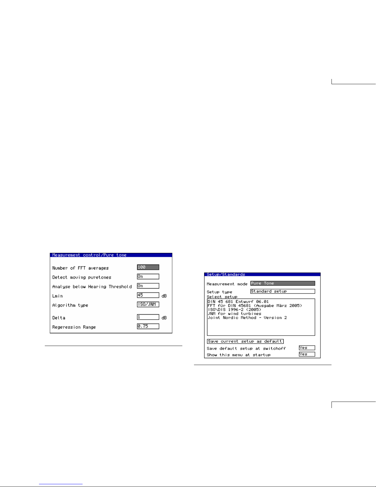
Improved possibilities
In the MeasSetup menu, there is now a choice between
the algorithm specified in the DIN 45 681 (Entwurf 2001)
and the algorithm specified in both the ISO/DIS 1996-2
(2005) and in the Joint Nordic Method—Version 2. For
the ISO/JNM algorithm, the parameters “Delta” and “Re-
gression Range” may also be adjusted. The operator may
speed up the pure tone analysis by deactivate the search
for moving pure tones, selecting the lowest level of analy-
sis (“Lmin”) and/or turning off any analysis below hearing
threshold.
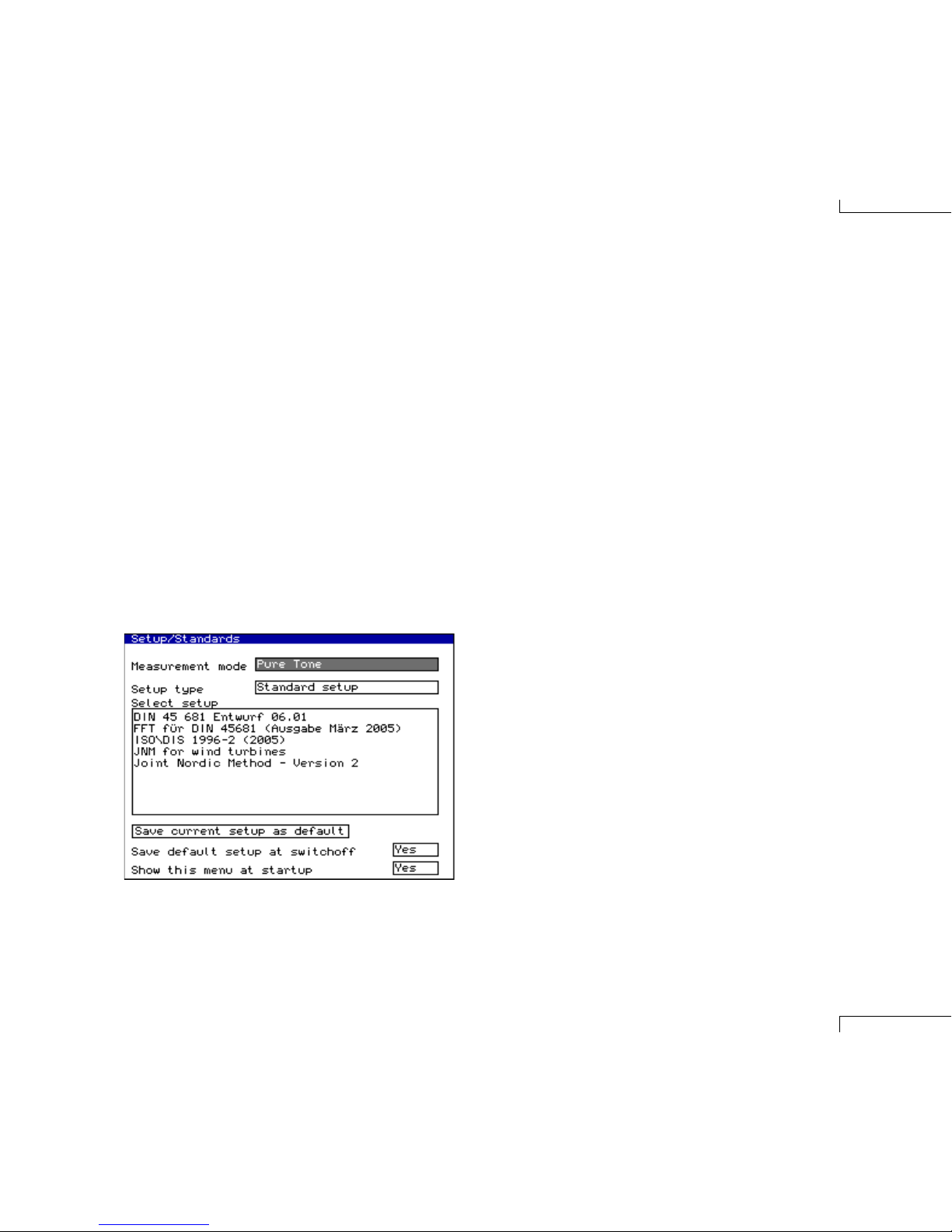
Pre-set pure tone Standards
In the Set-up/Standards menu, there is now a wider range
of preset Standards for pure tone analysis. This includes
all the above mentioned Standards plus the special Joint
Nordic Method (JNM) for wind turbines.
It is also possible to conduct FFT analysis for the use
with the DIN 45 681 standard from 2005. FFT data are
stored in the instrument and can be later transfered to a
PC where the pure tone analysis can be performed using
a special macro for Microsoft Excel.
Another possibility for performing a pure tone analysis
is to make recordings of the sound in the form of 16-bit
wav files. These files can then be transfered to a PC and
pure tone analysis can be done using the NorReview post
processing software
In the Set-up/Standards menu, the user may choose among
preset set-ups in accordance with misc. Standard proposals.
The MeasControl/PureTone menu now contains more features
in order to analyse for pure tones in accordance with different
Standard proposals.

Nor121
page 10
Building acoustic mode
Spectrum Adaptation Terms
The Average Rating Report is now also calculating the
Spectrum Adaptation Terms as given in the ISO 717
Standard. These terms are calculated both for airborne
and impact sound insulation measurements. When an ex-
tended frequency range is used for the measurement the
corresponding terms are calculated as well.
All the terms are displayed in a sub-menu that is ac-
cessed from the leftmost soft key below the display when
the Average Rating Report is displayed in either graphical
or numerical format.
The Spectrum Adaptation
Terms are calculated and
presented by a push on the
leftmost softkey displayed in
the Average Rating Report.

Instruction manual
page 11
Equalizer
General
Equalizer is a new feature introduced with software ver-
sion 4.0. It is used with signal generator in building acous-
tics mode to provide the user with even better control over
the excitation signal.
The international standard ISO 140-4 specifies that
the excitation signal shall be such that the level difference
between adjacent one-third-octave bands shall not be
greater then 6 dB. In other words it is required that the
frequency characteristic of excitation signal is sufficiently
flat. Rooms and loudspeakers hinder us from having this
requirement always fulfilled, hence we need an equalizer
to control the difference. This provides the possibility to
fine-tune the spectrum of excitation signal to every send-
ing room ensuring the fulfilment of standard requirements
and quality of measurement results.
Equalizer implementation characteristics
The equalizer implemented in Nor121 is a 21 band equal-
izer with one-third-octave bandwidth. The central frequen-
cies of filters are at one-third-octave bands’ mid-frequen-
cies from 50Hz to 5kHz.
Gain in each band can be adjusted from +6dB to -6dB.
If positive gains are used, the overall level will be cor-
respondingly lowered in order to prevent speaker and
amplifier overload. If the user needs more power it can be
added by increasing “Level” parameter from “Generator”
menu. However, it is advisable to use equaliser in order
to lower the levels in those bands where it is necessary
rather then to boost level in other bands.
Figure below shows that positive gain at one frequency
(upper curve) will result in negative gain correction of the
output. The result is that the actual gain cannot exceed 0
dB (lower curve) in order to protect the loudspeaker and
the amplifier.
Equalizer can be used with both noise excitation and
Swept-Sine excitation. Equalizer gains can be adjusted
while the generator is running with pink noise excitation.
If Swept-Sine excitation is used the gains has to be ad-
justed prior the measurement.
Please note the equalizer cannot be used with Swept-
Sine excitation when sweep duration parameter has value
“Long”.
Nor121
page 12
Equalizer can be used with both one-third-octave and
one-octave band resolution. When used with octave reso-
lution, gain is applied to all three one-third-octave bands
constituting that octave.
Equalizer gains are saved at instrument switch-off.
Using EQ with the pink noise excitation
- a cookbook
1. Place the speaker and microphone in the sending
room, and connect everything as desired.
2. Open generator menu
3. Press “Gen On/Off” software key again in order to start
the generator.
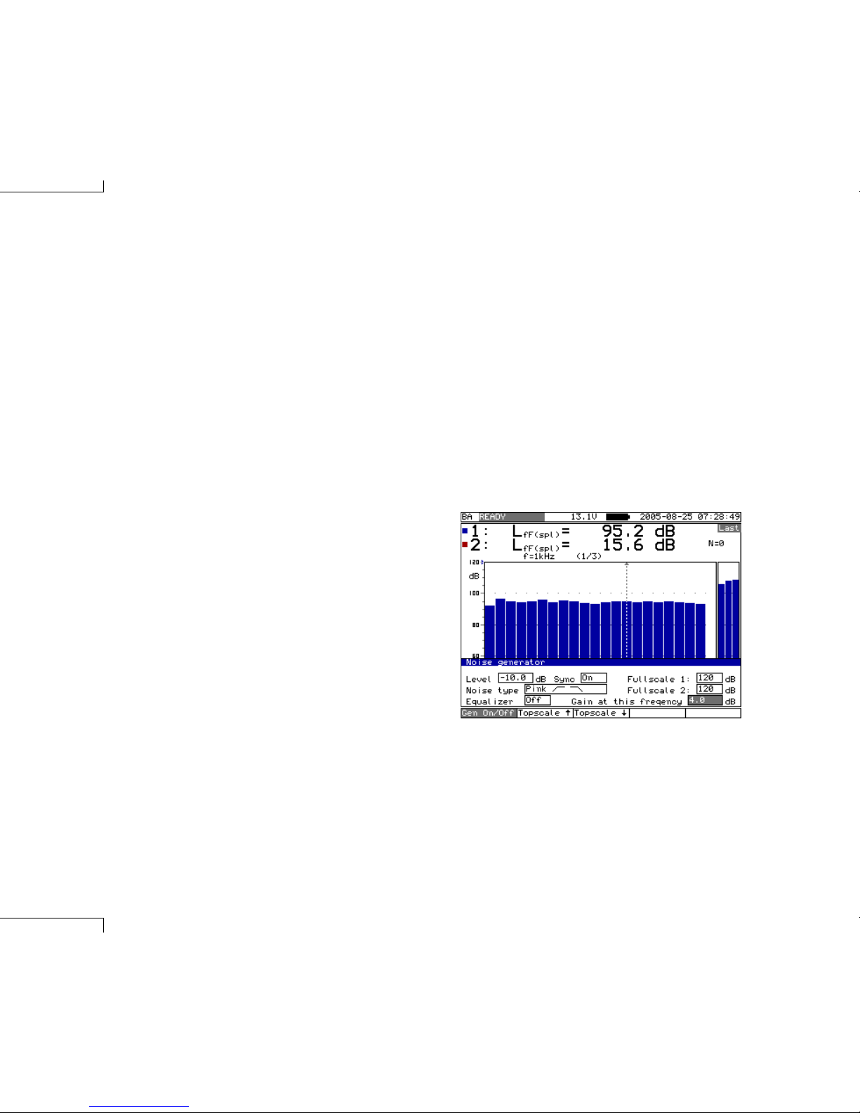
4. The measured levels in each band are shown on dis-
play, both as numerical values and graphically.
5. Use inner LEFT and RIGHT arrow keys to move cursor
between frequency bands. Current frequency can be
seen above the graphical display (e.g. f=1 kHz in the
figure)
6. While standing on the “Equalizer” parameter use in-
ner UP or DOWN keys to toggle between EQ “On” or
“Off”.
7. While standing on the “Gain at this frequency” pa-
rameter use inner UP or DOWN keys to adjust gain at
the frequency of the cursor. Gain is adjusted in 1 dB
steps.
8. Move the cursor to another frequency and if necessary
repeat the step 7.
Using EQ with the Swept-Sine excitation
- a cookbook
Basically the same as with the pink noise excitation ex-
cept that the generator can not be started separately and
therefore EQ cannot be adjusted while playing excitation
signal. Instead, the user is advised to do the following:
1. Make a test measurement first, look at the display that
shows the level in sending room.
2. Open the “Generator” menu and adjust EQ as desired.
3. Make a new measurement with EQ On.
As an alternative, you may adjust the equilizer by using
pink noise before the Swept-Sine mode is entered.
User interface
Open the “Generator” menu and two parameters related
to EQ are:
1. “Equalizer”, values: {On, Off}, turns generator on/off
2. “Gain at this frequency”, values: [-6, 6] dB, adjusts the
gain at each frequency band individually

Instruction manual
page 13
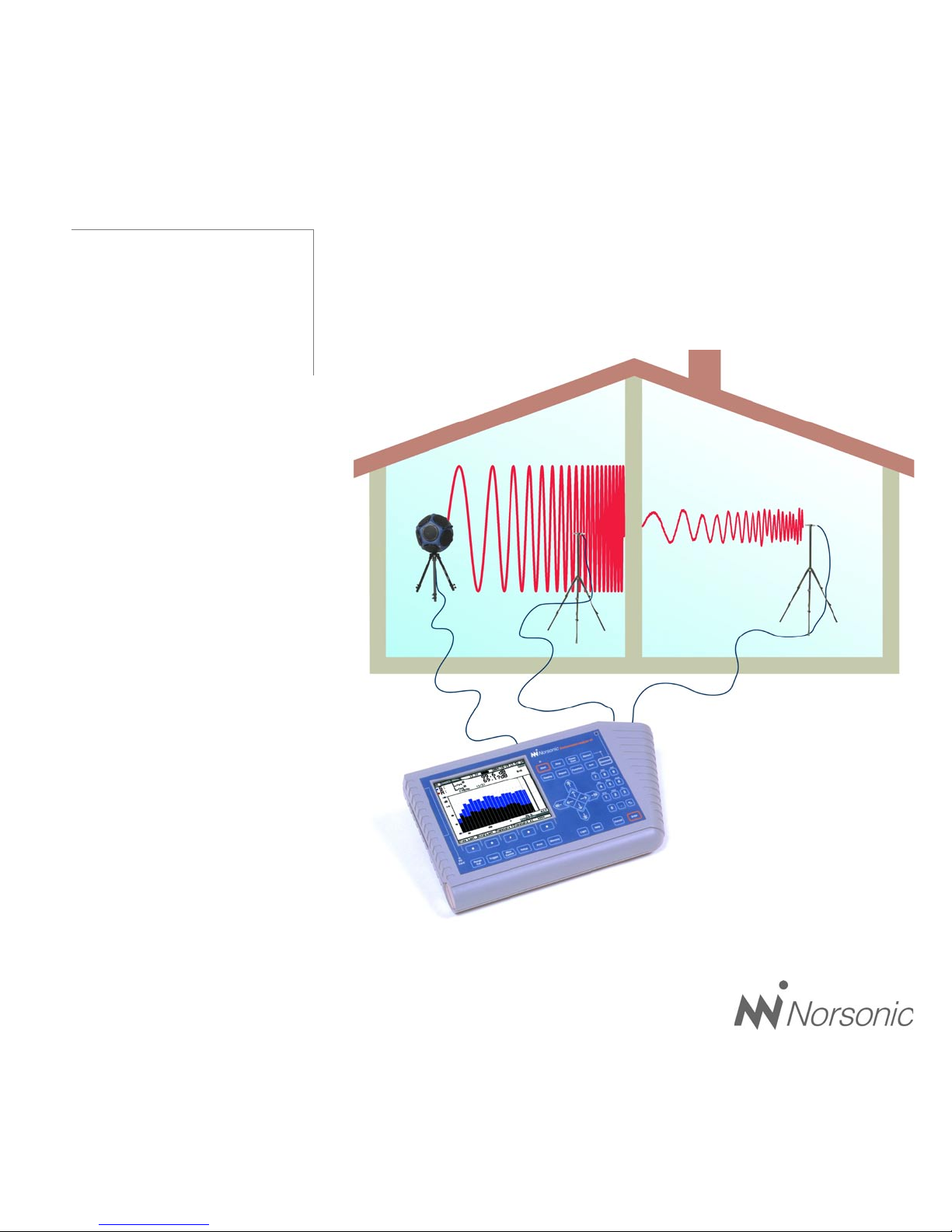
Swept-Sine
measurement technique
Building acoustic measurements under difficult situa-
tions, such as high background noise in the receiving
room, may be greatly improved by use of the Swept-
Sine measurement technique. This technique may also
be used for measurement on high-performance sound
insulations that is impossible to measure with traditional
technique.
The previous Norsonic analyzer Nor840 offered a similar
feature with its unique MLS (Maximum Length Sequence)
measurement mode. The new Swept-Sine technique
within the Nor121 analyzer is also based on the impulse
response of the measured rooms, but the Swept-Sine
technique is more robust for environmental influences
such as temperature and wind than the MLS technique.
Hence, Norsonic has taken a new step forward by imple-
menting a new improved feature.
Both the MLS and Swept-Sine measurement tech-
nique for use on building acoustics application are de-
scribed in ISO 18233. This new standard, currently at the
FDIS-stage, will probably be turned into a legal standard
early 2006, which means that sound insulation tests may
be performed using this new technique as an alternative
to the traditional ISO-140 technique.
The Swept-Sine measurement technique is available
for all Nor121 units equipped with version 4.x and the new
option 14 SweptSine technique.
Swept-Sine measurement technique is an optional ex-
tension for the Nor121. Furthermore, it is an extension of
building acoustic measurement mode of Nor121.
Swept-Sine based measurements on Nor121 can be
performed with two aims in mind. The first one is to obtain
results used in the building acoustics such as airborne
sound insulation and reverberation time. Application of
Swept-Sine technique to this type of measurement is de-
scribed in the first part of this chapter. As a contrast to this
highly specialized task, the second type of measurement
that Swept-Sine provides, is much more general. It is dual
or single channel measurement of broadband impulse
response and is described in second part of this chap-
ter. As an impulse response is a fundamental quality in
system analysis in general, its measurement with Nor121
can be performed in broad range of applications, even
beyond field of acoustics!

Nor121
page 14
Impulse response is also indirectly involved in the
classical method with noise excitation as the measured
response to such excitation can be described as a con-
volution between the excitation signal and the impulse re-
sponse of the room. However, in such case the response
to noise excitation is recorded directly and information
about the impulse response is normally not known.
Several new measurement methods may be applied
to obtain the impulse response as described in stand-
ard ISO 18233. One of those methods, based on use of
maximum length sequences (MLS) became very popular
in the 1980s due to the ability to use computer features
available at that time. However, MLS based techniques
have some undesirable properties such as vulnerability to
distortion and time variance. Those undesired properties
motivated further research which resulted in even more
advanced method, known as Swept-Sine.
The Swept-Sine is a measurement method, which uses
an excitation signal of a sinusoidal shape whose frequen-
cy increases from low to high frequencies. The response
to this excitation is recorded by the analyser and the im-
pulse response between source and receiver position is
extracted by the use of a mathematical technique known
as deconvolution.
Introduction -
What is Swept-Sine technique?
Classical method for the measurement of sound transmis-
sion phenomena uses random noise or impulse signals
as excitation. The resulting levels or decay times are de-
termined directly from the recorded responses.
In order to measure with greater accuracy and repeat-
ability, new measurement methods have been developed.
They use deterministic signals as excitation and apply
digital signal processing principles to obtain the impulse
response of system under test. This is a great advantage
as all acoustical parameters can be obtained from further
processing of the impulse response. This makes these
methods applicable to all areas of acoustics.
In building acoustics, this method is applicable to
sound pressures measured in rooms as well as to the
velocities measured on structures. In room acoustics im-
pulse response plays a central role as many acoustical
quantities can be derived from it, as specified in Inter-
national standard ISO 3382. Development of transducers
such as loudspeakers and microphones involves numer-
ous measurements of frequency response function, which
is linked to the impulse response by Fourier transform. Vi-
broacoustics, acoustical profiling (sonar) and many other
areas are closely linked to measurement of impulse re-
sponses. Even high-end fields like virtual acoustic, which
is a part of virtual reality strongly rely on convolution with
impulse responses with high signal to noise ratio.
Building Acoustics measurements
using Swept-Sine technique
Table of contents
Other Norsonic Measuring Instrument manuals

Norsonic
Norsonic nor140 Operating and maintenance manual

Norsonic
Norsonic NOR150 User manual

Norsonic
Norsonic NOR150 User manual

Norsonic
Norsonic nor145 User manual

Norsonic
Norsonic nor103 User manual

Norsonic
Norsonic Nor1545 Instruction Manual

Norsonic
Norsonic nor118 User manual

Norsonic
Norsonic nor140 User manual

Norsonic
Norsonic nor145 User manual

Norsonic
Norsonic nor103 User manual

Popular Measuring Instrument manuals by other brands


Hasselblad
Hasselblad Meter Prism Finder PME90 user manual

K-Patents
K-Patents SAFE-DRIVE PR-23-SD Pocket guide

Martini Instruments
Martini Instruments MI 404 user manual

CCS
CCS WattNode WNC-3Y-208-MB Installation and operation manual

Matis
Matis matismart MTAF1-32 Manual instruction

LMI
LMI G-WHIZ user manual