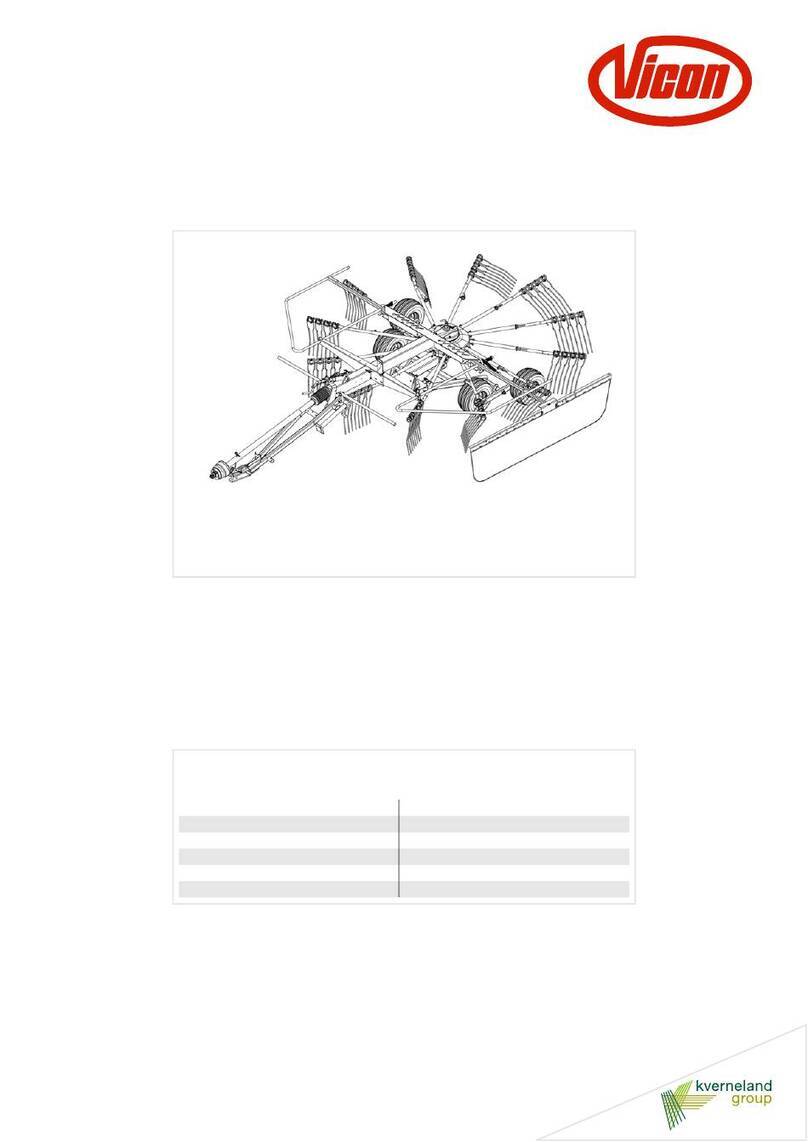
Vicon EXTRA 832 R Pro User manual

EXTR832 R Pro - 835 R Pro -
835 CR Pro
Monteringsanvisning
Assembly instructions
Instructions d’assemblage
Montierungsanleitung
Sprog/Language/Langue/Sprache DA / EN / FR / DE
No.: 90015433
Index: 2012-02

DA
HENVISNING TIL MODTAGER
Denne vejledning beskriver udpakning og montering af maskinen.
Maskinen er adskilt i hovedkomponenter, som samles efter denne montageanvisning. Følg anvisningens montage
rækkefølge og anvend de viste boltetyper og størrelser, til samling af delene, - se efterfølgende symboler.
Dette advarselssymbol henviser til forskrifter, der vedrører Deres egen sikkerhed og tredie-
mands sikkerhed.
Samling af maskiner generelt, må kun foretages af faguddannet servicefolk med kendskab til sikker brug af værk-
stedsudstyr. Til samling af nogle maskintyper, kræves også kendskab til brug af traktorens hydraulik eller hydraulisk
pumpestation.
Undgå løsthængende beklædning, som kan blive fanget af maskindele !
Anvend personligt beskyttelsesudstyr, som er nødvendig for det pågældende arbejde.
Anvend kun godkendt og holdbart løftegrej. Beskyt løftegrejet for skarpe kanter og undgå at eventuelle kæder snor
sig.
Inden makinen tages i brug første gang og af hensyn til sikkerheden skal den medfølgende brug-
sanvisning læses grundigt.
EN
INSTRUCTIONS FOR THE RECIPIENT
These instructions describe unpacking and assembly of the machine.
For the transport from the factory to the user the machine has been dismantled in main components. The following
assembly instructions will tell you how to reassemble the machine. Please follow the assembly order shown and
use the types and sizes of bolts shown for assembly of the parts. Look for the following symbols:
This warning symbol refers to instructions concerning your own safety and the safety of third
party.
In general, assembly of machines should only be carried out by skilled service staff having knowledge of safe use
of workshop tools. The assembly of some machine types also requires knowledge of the tractor hydraulics or hy-
draulic pump station.
Do not use loose-fitting clothes. They could be caught by machine parts!
Use the personal protection equipment which is necessary for the work in question.
Only use approved and adequate lifting equipment. Protect the lifting equipment from sharp edges and prevent
strings/chains from winding.
Thoroughly read the instruction manual delivered with the machine before taking the machine
into use for the first time and to ensure safe working.
bolte med rundt hoved
bolte med 6-kant hoved
bolts with hexagon head bolts with round head

FR
INSTRUCTIONS ADDRESEES AU DESTINATAIRE
Les instructions ci-après decrivent le désemballage et l’assemblage de la machine.
Pour le transport, la machine a été démontée en composantes principales. Pour le réassemblage de la machine,
suivre les instructions d'assemblage dans l'ordre mentionné. Utiliser les types and tailles des boulons montrés pour
l'assemblage des composantes. Faire attention aux symboles suivantes:
Ce symbole d’avertissement se refère aux instructions concernant votre sécurité et la sécurité
du tiers
En général, l'assemblage des machines ne doit pas être confié qu'au personnel professionnel qui sait manier l'out-
illage d'une manière sûre. Pour l'assemblage de certaines machines, il faut aussi avoir connaissance de l'hy-
draulique du tracteur ou de la station de pompage hydraulique.
N’utilisez pas de vêtements lâches qui peuvent être attrappés par la machine!
Utilisez un équipement protecteur personnel qui convient pour le travail en question.
Utilisez toujours un matériel de levage conforme et de capacité de charge suffisante. Protéger le matériel contre
des arêtes vives et évitez que les chaînes éventuelles se virent.
Avant la mise en service de la machine pour la première fois et pour raisons de la sécurité, il faut
lire attentivement le manuel d’instructions livré avec la machine.
DE
HINWEISE FÜR DEN EMPFÄNGER
Die vorliegende Anleitung beschreibt das Auspacken und die Montage der Maschine.
Für den Transport vom Werk an den Benutzer wurde die Maschine in Hauptkomponenten zerlegt. Die folgende
Montageanleitung beschreibt die Montierung der Maschine. Bitte die in der Anleitung erwähnten Reihenfolge befol-
gen und die gezeigten Bolzentypen und -Größen verwenden. Die folgenden Symbole beobachten:
Dieses Warnsymbol kennzeichnet Hinweise, die Ihre eigene Sicherheit und die Sicherheit Dritter
betreffen
Montierung von Maschinen sollte immer nur von Fachleuten, die mit Werkstattausrüstung vertraut sind, ausgeführt
werden. Die Montierung einiger Maschinen erfordert auch Kenntnis von Schlepperhydraulik oder hydraulischer
Pumpenstation.
Locker getragene Kleidung vermeiden! Sie kann sich in Machinenteile verfangen.
Persönliche Schutzausrüstungen tragen, die für die jeweilige Arbeit notwendig sind.
Nur einwandfreie Hebezeuge mit ausreichender Festigkeit benutzen. Die Hebezeuge ausreichend vor scharfen
Kanten schützen und bei Ketten Schlaufebildung vermeiden.
Vor dem Ersteinsatz und für sicheres Arbeiten mit der Machine unbedingt die mit der Maschine
gelieferte Bedienungsanleitung lesen.
Kverneland Group Kerteminde AS
DK-5300 Kerteminde - Denmark
Phone / Fax: +45 65 19 19 00 / +45 65 19 19 99
web: www.kvernelandgroup.com
Boulons à tête hexagonale Boulon à tête ronde
Bolzen mit Sechskantkopf Bolzen mit rundem Kopf

4
Tilspændingsmoment:
Tilspændingsmoment for bolte af kvalitet 4.6 - 5.8
- 8.8 - 10.9 - 12.9 sort og/ellerblankforzinkede og
usmurte, når der spændes på glat overflade eller
almindelige spændeskiver.
Torque moment:
Torque moment for bolts of quality 4.6 - 5.8 - 8.8
- 10.9 - 12.9 black and/or galvanized and un-
greased when tightened on a smooth surface or
a plain washer.
Couples de serrage:
Couples de serrage pour vis qualité 4.6 - 5.8 -
8.8 - 10.9 - 12.9, noires et/ou galvanisées,
dégraissées, sur surface lisse ou rondelle plate.
Anzugdrehmoment:
Drehmoment für Schraube Qualität 4.6 - 5.8 - 8.8
- 10.9 - 12.9 schwarz und/oder galvanisiert und
ungeschmiert, beim Festziehen an einer glatten
Oberfläche oder mit gewöhnlicher Federscheibe.
NB !
Brug altid orginale VICON-dele af sikker-
hedsmæssige hensyn.
NB !
For safety reasons use only original VICON
parts.
NB !
Pour des raisons de sécurité utiliser exclusive-
ment des pièces d'origine.
NB !
Aus Sicherheitsgründen dürfen nur Original-VI-
CON Ersatzteile verwendet werden.
Dim.
Boltkvalitet / Bolt quality / Qualité du boulon / Bolzenqualität
4.6 5.8 8.8 10.9 12.9
Nm lbs.pi Nm lbs.pi Nm lbs.pi Nm lbs.pi Nm lbs.pi
M5 2 1,6 3,5 2,5 5,5 4 8 6 10 7
M6 3,5 2,6 64,5 10 714 10 17 12
M8 9 6,4 15 10,5 24 17 33 23,5 40 28,5
M10 17 12 29 21 47 33,5 65 46,5 79 56,5
M12 3021,55136,581 5811481,513697
M14 48 34 80 57 128 91,5 181 130 217 155
M16 74 53 123 88 197 141 277 200 333 238
M18 103 73,5 172 123 275 196,5 386 275 463 330
M20 144 103 240 171,5 385 275 541 386,5 649 463,5
M22 194 138,5 324 231,5 518 370 728 520 874 624
M24 249 178 416 297 665 475 935 668 1120 800
5
>
Fjern løse dele fra maskinen.
>
Remove loose parts from the machine.
>
Brug kranudstyr ved fjernelse af hjul.
>
Use crane equipment to remove the wheels.
55 kg

6
>
Monter kranudstyr i det viste beslag.
NB! Kranudstyret skal have en minimums ka-
pacitet på 2000 kg.
>
Attach the crane equipment to the bracket shown.
NB! The crane equipment must have a mini-
mum capacity of 2000 kgs.
ADVARSEL!
Alle personer skal opholde sig i en sikker af-
stand til maskinen når denne vendes.
WARNING!
All persons must keep a safe distance to the
machine when it is turned.
>
Løft maskinen
meget forsigtigt
og lad den vippe
over som vist. Sænk derefter maskinen ned med
kranudstyret og stil den på gulvet som vist.
>
Very carefully
raise the machine and let it tilt over
as shown. Then lower the machine with the crane
equipment and place it on the ground as shown.
Min. 2000 kg
Min. 2000 kg

7
>
Fjern kranudstyr. Fjern transportsikring og beslag
og fjern frontafskærmningen.
>
Remove the crane equipment. Remove the trans-
port safety device and bracket and remove the
front guard.

8
>
Monter stropper for kran som vist.
>
Mount straps for crane as shown.
Højre/Right
>
Vær opmærksom på at strop er placeret som vist.
>
Make sure that the strap is fitted as shown.
Venstre/Left
>
Vær opmærksom på at strop er placeret som vist.
>
Make sure that the strap is fitted as shown.

9
>
Løft maskinen op, så transportstativ er fri af gulvet.
Fjern bolte ved høstebjælke i begge sider.
>
Lift the machine so that the transport frame is clear
of the ground. Remove the bolts on the cutterbar in
both sides.
>
Træk transportstativet ud som vist og sænk mask-
inen ned på gulvet. Stativet frigøres nu fra maskin-
en. Fjern transportstativ.
>
Pulloutthetransportframe asshownandlowerthe
machine onto the ground. Dismount the transport
frame from the machine and remove it.

10
>
Løft maskinen op og understøt høstebjælken med
paller eller klodser på mellem 400 til 450 mm i
begge side af høstebjælken som vist. Sænk mask-
inen ned på understøtningen.
>
Raise the machine and support the cutterbar with
pallets or blocks of between 400-450 mm on both
sides of the cutterbar as shown. Lower the ma-
chine onto the support.
>
Fjern transportbeslag i begge sider af maskinen.
>
Removethetransportbrackets onbothsidesofthe
machine.
400 - 450 mm

11
>
Fjern transportbeslag i begge sider af maskinen.
>
Removethetransportbrackets onbothsidesofthe
machine.

12
Højre/Right
>
Demonter bolte fra beslag og hæv maskinen op og
monter beslag som vist.
>
Remove the bolts from the bracket and raise the
machine and fit the bracket as shown.
Venstre/Left
>
Monter aksel og bolt. Vær opmærksom på hullet i
akslen.
>
Mount the axle and bolt. Pay attention to the hole
in the axle.

13
>
Demonter stropper fra maskinen.
>
Demount the straps from the machine.
>
Tilslut maskinens hydrauliske system til traktor
eller hydraulisk pumpestation og løft maskinens
hovedramme helt op.
>
Connectthehydraulicsystem ofthemachinetothe
tractor or hydraulic pump station. Lift the main
frame of the machine.

14
>
Flyt armen til den viste position. Indsæt bøs som
vist.
>
Move the arm to the position shown. Insert bush as
shown.
>
Adskil lås for ophæng.
>
Separate the lock for suspension.

15
>
Før hydraulikcylinderen igennem begge bøs som
vist. Monter skive og låsering.
>
Leadthe hydrauliccylinder throughbothbushesas
shown. Mount the washer and circlips.

16
>
Placer hydraulikcylinderen i den viste stilling.
>
Place the hydraulic cylinder in the position shown.
>
Spænd hydraulikcylinderen fast med den viste bolt
og spænd kontramøtrik til.
>
Tighten and secure the hydraulic cylinder with the
bolt shown and tighten the counter nut.

17
>
Tilslut maskinens hydrauliske system til traktor
eller hydraulisk pumpestation og træk maskinens
hovedramme helt sammen med maskinens høs-
teenhed.
>
Connectthehydraulicsystem ofthemachinetothe
tractor or to a hydraulic pump station. Push the
main frame quite close to the cutting unit of the ma-
chine.

18
Kun CR maskine/Only CR machine/
>
Monter kranudstyr eller lignende udstyr under kon-
sol.
>
Demonter alle 4 bolte.
>
fit crane equipment or similar equipment under the
main bracket.
>
Remove all 4 bolts.
>
Sænk forsigtigt konsollet og gear ned på gulvet og
demonter konsollet fra gearet.
>
Carefully lower the main bracket with the gear box
down on the floor and remove the main bracket
from the gear box
>
Løft gearet op og placer det under trækstang som
vist.
>
Løft gearet op under trækstang og genbrug bolte
og monter og fastgør gear på trækstang som an-
vist.
>
Lift up the gear og place it under the drawbar as
shown.
>
Lift up the gear under the drawbar, re-use the bolts
and fit and secure it under the drawbar as indicat-
ed.
M12 x 20
(4 pcs)
Nord-Loc
(4 pcs)
NB!
80 Nm

19
>
Tag PTO akslen med splines, træk manchetten til-
bage som vist og demonter bolt.
N
B
!
Vær opmærksom på smørehullet på manchetten
er vendt som vist.
>
Take the PTO shaft with the splines and pull back
the sleeve as shown and remove the bolt.
N
B
!
Take notice that the greasing hole on the sleeve
is turned as shown.
>
Husk spændebåndet og monter PTO akslen som
vist.
>
Kontroller at smørehullet er placeret rigtigt.
>
Fastgør PTO med bolt.
>
Rememberthe hoseclamp andfit thePTO shaftas
shown.
>
Check the crease hole is in the position.
>
Secure the PTO shaft with the bolt.
Smørehul /
Grease hole
Smørehul /
Grease hole

20
>
Tag PTO akslen med notgang, træk manchetten
tilbage som vist og demonter bolt.
N
B
!
Vær opmærksom på smørehullet på manchetten
er vendt som vist.
>
Kontroller og drej akslen på trækstang så noten er
vendt mod trækstang.
>
Take the PTO shaft with the splines and pull back
the sleeve as shown and remove the bolt.
N
B
!
Take notice that the greasing hole on the sleeve
is turned as shown.
>
Check and turn the shafton thedrawbar so thatthe
key is facing towards the drawbar.
>
Husk spændebåndet og monter PTO akslen som
vist.
>
Kontroller at smørehullet er placeret rigtigt.
>
Fastgør PTO med bolt.
>
Rememberthe hoseclamp andfit thePTO shaftas
shown.
>
Check the crease hole is in the position.
Secure the PTO shaft with the bolt
Smørehul /
Grease hole
Drej aksel så not er
vendtmodtrækstang
Turn the shaft so that
the key is facing to-
wards the drawbar
Smørehul /
Grease hole
This manual suits for next models
2
Table of contents
Other Vicon Farm Equipment manuals

Vicon
Vicon Fanex 524 T User manual

Vicon
Vicon Andex 844 User manual

Vicon
Vicon Andex 1104 User manual

Vicon
Vicon EXTRA 332 F User manual

Vicon
Vicon Fanex 464 User manual

Vicon
Vicon RF121 R User manual

Vicon
Vicon Extra 224 User manual

Vicon
Vicon Andex 714 T Evo User manual

Vicon
Vicon Andex 323 User manual

Vicon
Vicon EXTRA 690 T User manual

Vicon
Vicon RV 1601 User manual

Vicon
Vicon Andex 714 T Vario User manual

Vicon
Vicon Extra 390 User manual

Vicon
Vicon Extra 390 User manual

Vicon
Vicon Extra 532 User manual

Vicon
Vicon Andex 694 EVO User manual

Vicon
Vicon Extra 328 User manual

Vicon
Vicon EXTRA 632 T User manual

Vicon
Vicon Andex 474 T User manual

Vicon
Vicon CM 299 User manual