Sioux Tools DAAY POWER SWEEP User manual

MANUAL NO. 712702 3/23/2022
OWNERS MANUAL

Introduction
•The purpose of this manual is to explain the operation and maintenance of the paddle sweep. It
also contains a parts list for reference if replacement parts are needed.
•It is recommended that you read this manual in its entirety for the information available in
order to provide the proper care and maintenance of the paddle sweep. The equipment is built
to provide many years of dependable service when used properly. Reading this manual will also
provide information on how to use the equipment correctly to prevent any accidents while using
the system.
•If you have any further questions, comments, improvements, or suggestions regarding the
contents of any of the manuals provided, please see the contact information below.
•This machine is covered by one or more United States patents. Refer to www.siouxsteel.com for
current patent information. Or scan this QR Code to go directly to the patent area on the
website.
ALL safety decals are no charge from the factory.
Please replace all safety decals if damaged or missing.
Your safety is important
WARNING! Anyone who will be operating or working around the equipment should first read this
manual to familiarize themselves with the machinery.
Sioux Steel Company
196 1/2 East 6th Street
Sioux Falls, SD 57101-1265
Phone: 1-800-557-4689
www.daaybinsweep.com

Contents
1Sweep Terminology..............................................................................................................................1
2Safety Information ...............................................................................................................................3
2.1 Safety Alert Symbol......................................................................................................................4
2.2 Safety & Logo Decals....................................................................................................................5
3Specifications........................................................................................................................................6
3.1 Features ........................................................................................................................................6
3.2 Burial Depth Chart........................................................................................................................7
3.3 Overall Dimensions & Weights....................................................................................................8
4Setup.....................................................................................................................................................9
4.1 Prior to Installation ......................................................................................................................9
4.2 Installation..................................................................................................................................11
4.3 Head Section Assembly..............................................................................................................12
4.4 Intermediate Sections and Paddle Chain Installation...............................................................14
4.5 End Drive Section Assembly and Installation............................................................................17
4.6 Paddle Chain Tensioning............................................................................................................20
4.7 Final Check..................................................................................................................................21
4.8 Initial Operation .........................................................................................................................22
4.9 Track Pathway Installation.........................................................................................................23
4.10 Zero Entry Pad Installation.........................................................................................................23
4.11 Setting the sweep for Burial ......................................................................................................25
5Operation............................................................................................................................................27
6Preventative Maintenance.................................................................................................................28
7Trouble Shooting................................................................................................................................30
8Parts Diagrams....................................................................................................................................31

1
1Sweep Terminology
Head Section
Intermediate Section
Pivot Kit
Drive End
Paddle Chain
Jack Stand

2
Caster Wheel
Zero Entry

3
2Safety Information
•A careful operator is the best operator. Most accidents can be avoided by observing necessary
precautions. To help prevent accidents, read the following precautions before operating this
equipment. Equipment should be operated only by those who are responsible and instructed to do
so. Carefully review the procedures given in this manual with all operators. It is important that all
operators be familiar with and follows safety precautions. Improper use of the equipment can cause
serious injury or death.
•Read the operator’s manual before operating equipment.
•Only allow properly trained persons to operate the equipment.
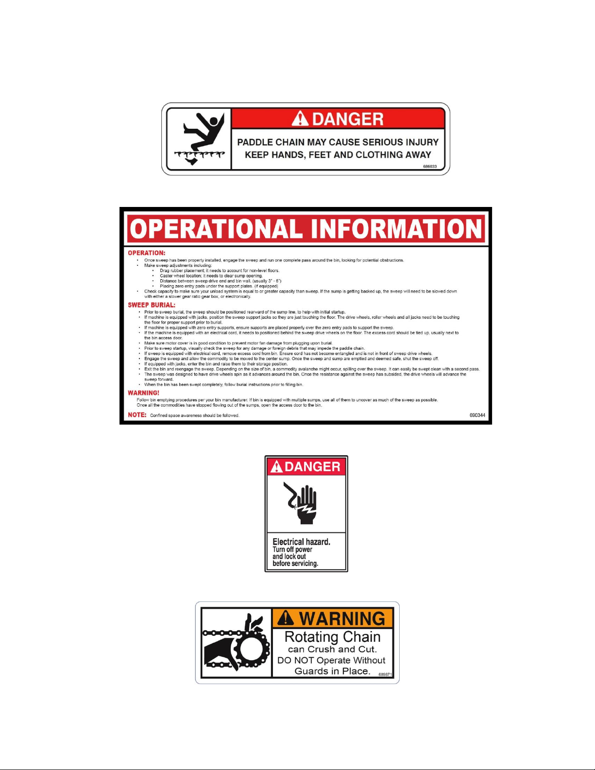
•Keep hands and feet away from all pinch points.
•Keep bystanders away during operation. In an empty bin/silo, keep everyone rearward of the
sweep during operation to validate installation or maintenance.
•Do not contact (i.e., push, stand, touch, etc.) any portion of the sweep during operation.
•Since the installation of this sweep takes place within a confined space. Confined space awareness
should be followed. Lockout/tag out awareness should be followed.
•A licensed electrician is recommended to wire the unit in accordance with local federal codes.
•DO NOT clean, lubricate, or adjust the equipment while it is running. Disengage the machine prior
to doing so.
•Install and ground slip collector ring and the entire unit in accordance with the National Electric
Code (NEC) and local codes and/or ordinances.
•Always disconnect and lock out all power sources from the collector ring before attempting to
perform any service function. Follow lockout/tag out procedures as outlined in OSHA section
1910.147 where appropriate.
•An explosion proof motor is required for use in a Class II, Group E, F, G dust environment.
•Refer to maintenance chart to check all fasteners and hardware to assure tightness.
•CAUTION: Too much oil will cause overheating and too little will result in gear failure. Check oil level
regularly. More frequent oil changes are recommended when operating continuously, at high
temperatures or under conditions of extreme dirt or dust. Check that the vent plug is clear.
•Contact the bin manufacturer for anchor design on grain bins 72 feet in diameter and larger for
single pass sweep utilization. Failure to do so may cause damage to the grain bin.
•REMEMBER: The manufacturer includes or provides all reasonable means for accident prevention
except a safe and careful operator.

4
2.1 Safety Alert Symbol
•The symbol shown below is used to call your attention to instructions concerning your personal
safety. Watch for this symbol it points out important safety precautions. It means ATTENTION!
Be Alert! Your Personal Safety Is Involved!
DANGER: Indicates an imminently hazardous situation that, if not avoided, will result in
death or serious injury. The color associated with Danger is RED.
WARNING: Indicates a potentially hazardous situation that, if not avoided, could result
in death or serious injury. The color associated with Warning is ORANGE.
CAUTION: Indicates a potentially hazardous situation that, if not avoided, may result in
minor or moderate injury. The color associated with Caution is YELLOW.

5
2.2 Safety & Logo Decals
▪686033 DANGER –Paddle chain may cause serious injury keep hands, feet and clothing away.
▪690344 –Operation Information
▪688462 DANGER - Electrical Hazard. Turn off power and lock out before servicing.
689771 WARNING –Rotating chain can crush and cut. Do NOT operate without guards in place.

6
3Specifications
(Specifications are subject to change without notice and without liability)
3.1 Features
•Farm Series
•Theoretical Capacity: Up to 5,000 BPH. Note: These values can fluctuate greatly depending on
the varying conditions present, including but not limited to; moisture content, grain commodity
type and flowability, amount of foreign matter present, and compaction rate. These all play a
part in the performance of the paddle sweep. Paddle sweep capacity may also vary as the angle
of the sloping grain varies. For optimal performance, dry flowable grain is recommended. The
paddle sweep is not intended for use in high moisture grain storage applications or suitable for
non-grain commodities including fertilizer, lime, etc. Also, grain that may have gone out of
condition due to moisture or insect activity and has become hard or caked will result in
diminished capacity.
•Drive tire size: 5” x 8” -15” height segmented wheel
•Drive wheel powered by a gearbox off the paddle chain.
•Designed to be fully submersed in grain
•Housing is made from 12 ga. Steel
•Moves grain gently and evenly to sump
•Adjustable chain mount
•Flexible pivot joint allows sweep to move independently from gearbox to allow for variations in
the bin floor
•Adjustable stabilizer arms to accommodate variations in bin size and out of roundness
•Rubber drag to clean the floor for less sweeping

7
3.2 Burial Depth Chart
Sweep Model Bin/Silo Type
Support
System
15' 18' 21' 24' 27' 30' 33' 36' 42' 48' 54' 60' 66' 72' 75' 78' 90' 105' 116' 124' 132' 135' 139'
Daay Power
Farm
Corrugated Bin
Jacks 30'
Daay Power
Farm
Corrugated Bin
Zero Entry
Interceptor Corrugated Bin Jacks
Interceptor Corrugated Bin Zero Entry 60'
Daay Bin
Paddle & DPS
G2
Corrugated Bin
Jacks 105' 95' 80' 75'
Daay Bin
Paddle & DPS
G2
Corrugated Bin
Zero Entry 140' 135' 115' 106'
DPS 12K Corrugated Bin Zero Entry 139' 136' 125' 114' 106' 99' 95' 88' 88' 84'
Daay Bin
Paddle & DPS
G2
Concrete Silo
Jacks 135' 115' 105' 100' 95' 85' 75'
Daay Bin
Paddle & DPS
G2
Concrete Silo
Zero Entry 150' 125' 106'
DPS 12K Concrete Silo Zero Entry 139' 136' 125' 114' 106' 99' 95' 88' 88' 84'
*If eave height is over the listed height, please contact manufacture.
MAX. EAVE HEIGHT/BURIAL DEPTH CHART FOR PADDLE SWEEPS
Bin/Silo Diameters
Floor to Eave Height
70'
40'
35'
Floor to Eave Height
NA
NA
NA
70'
60'
70'
40'
35'
NA
NA
NA
115'
90'
150'
NA
NA
70'
NA
NA
160'
160'
150'
150'

8
3.3 Overall Dimensions & Weights
Sweep Unit for Bin
Size
Length
(Dim A)
Length
(Dim B)
Height
(Dim C)
Width
(Dim D)
Unit Weight (lbs)
15’
8’
18”
37”
33”
501
18’
9’
536
21’
11’
572
24’
12’
605
27’
13’
640
30’
15’
675
33’
16’
709
36’
18’
771
42’
21’
840
48’
24’
909
54’
27’
1006
60’
30’
1075
66’
33’
1144

9
4Setup
4.1 Prior to Installation
•Extra floor supports or structure will be required to support the sweep during burial if a full aeration
floor is used. These supports or structure will need to be placed directly underneath the zero entry
pads/jacks/caster wheels to support the sweep in the burial condition. Failure to do so will result in
damage to the paddle sweep, sweep accessories, and aeration floor.
•When locating the sump locations in the bin foundation it is critical to consider where the wheel
paths are going to be located. Below is a chart and illustration of these paths to match to your
sweep model.
•If the sweep wheel path does interfere with a sump location the sump will need to be grated or
covered to allow the wheel to cross without falling into the sump.
Power Farm - Wheel Paths
Nominal
Bin Dia.
Sweep
Length
Actual Bin
Radius
First Roller Wheels Path
Between Dim's (Head
Section)
Outer Drive Wheel Path
Between Dim's
A
B
C
J
K
Paddle Sweeps with Standard Configuration
15'
7' 6"
7' 5.5"
5’ 4”
7’ 0”
4' 9”
6' 8”
18'
8' 6"
8' 11.5"
5’ 4”
7’ 0”
6’ 3”
8’ 2"
21'
10' 6"
10' 5.5"
5’ 4”
7’ 0”
7’ 9”
9' 8"
24'
11' 6"
11' 11"
5’ 4”
7’ 0”
9’ 3”
11’ 2”
27'
12' 6"
13' 5"
5’ 4”
7’ 0”
10’ 9”
12’ 8”
30'
14' 6"
14' 11"
5’ 4”
7’ 0”
12’ 3”
14’ 2”
33'
15' 6"
16' 5"
5’ 4”
7’ 0”
13’ 9”
15’ 8”
36'
17'-6"
12' 11"
5’ 4”
7’ 0”
15’ 3”
17’ 2”
42'
20'-6"
20' 10.5"
5’ 4”
7’ 0”
18’ 3”
20’ 2”
48'
23'-6"
23' 10.5"
5’ 4”
7’ 0”
21’ 3”
23’ 2”
54'
26'-6"
26' 10"
5’ 4”
7’ 0”
24’ 3”
26’ 2”
60'
29'-6"
29' 10"
5’ 4”
7’ 0”
27’ 3”
29’ 2”
66’
32’-6”
32’-10”
5’ 4”
7’ 0”
30’ 3”
32’ 2”

10
•Wheel Diagram
•Note: Wheel Diagram has additional information NOT relevant to setup of the interceptor sweep
(“D” “E” “F” “G” “H” “I”) (Inner Drive Wheel Path) (Middle Drive Wheel Path)
•For the sweep to properly operate and not acquire unnecessary damage the floor must be smooth
with no obstructions more than 3/16”.
•For the sweep to properly operate and not acquire unnecessary damage the floor gradient may not
change more the ½” in height in a 5’ span
•The center sump of the grain bin will need to be reviewed to determine which bin center pivot
section is going to be installed and what modifications may need to be made. The bin center pivot
options can be viewed later in this manual.
•Warning! Since the installation of this sweep takes place in a confined space; confined space
awareness should be followed in addition to any regulations and safety precautions.
"I"
"H"
"A"
"J"
"K"
"G"
"F"
"D"
"E"
"B"
"C"
WHEEL PATH
FIRST ROLLER
WHEEL PATH
SECOND ROLLER
INNER DRIVE
WHEEL PATH
MIDDLE DRIVE
WHEEL PATH
WHEEL PATH
OUTER DRIVE
BIN WALL

11
4.2 Installation
•It is recommended that the bin be empty and free of grain when the sweep is installed. If this can’t
be achieved, then a large enough area must be cleared that the sweep can be installed on a clean
floor and free from entrapment danger.
•We recommend the use of steel track pathways on any portion of aeration floor that the steel
wheels on any of the sweeps and the drive wheel on the farm sweeps contact. Failure to do so will
result in damage to the paddle sweep, sweep accessories, and aeration floor.
•It is recommended that at least three people install a sweep as the parts can be large and difficult to
handle.
•A tripod kit is available to assist in lifting components and moving them across the bin floor. The
tripod can be collapsed to fit through any size door.
•Since the power for the Daay Power Sweep is thru the gearbox, lock out tag out procedures should
be followed.
•Tools Needed
•Cordless Driver
•Ratchet
•1/2” & 9/16” shallow socket
•1/2” & 9/16” deep socket
•(1) 5/8” wrench
•(1) 3/4” wrench
•(1) 15/16” wrench (for tightening paddle chain)
•(2) Alignment punches
•(1) Center punch
•Battery powered/Explosion proof light
•Pliers/Needle Nose
•10’ of wire (for pulling paddle chain through)
•Standard Allen wrench set
•Gloves
•Hammer
•Loctite (blue)

12
4.3 Head Section Assembly
•Overview –The installation of the head section will determine the final location of the
sweep. So, planning the pin location is critical to avoid having to move the entire sweep.
Head Section –
1.Reference the following parts of this
manual. See Table of Contents for specific page
numbers.
Pivot End Assembly Diagram for an overall
detailed view.
Pivot End Assembly Parts List for the proper
fasteners.
2. Locate the appropriate hardware to assemble
the Pivot end from the hardware bag that came
with the sweep.
3. Install the Pivot Stabilizer Bushing (K688936)
and the Stabilizer Lock Arm (K688914) on both
sides of the Pivot End Assembly (K704800).
Tighten the nuts using an 1 1/8” wrench, refer
to the torque spec sheet on page (33)
Make sure the lock arms rotate with minimal
resistance. If the arms are difficult to rotate,
disassemble the arm and check the hole on the
arm for potential burs or paint build up. Use a
round file or abrasive cloth to remove bur or
build up. Reassemble and re-check the
resistance. Repeat the process if necessary.

13
4. Install the pivot front caster wheel assembly
(K704838) and pivot rear caster wheel assembly
(K689824) to the pivot end assembly.
· Ensure that the carriage bolts are all facing
outward to avoid damage to the paddle as it
travels through the head section housing.
5. Install the stabilizer weldment (K688970) to
the stabilizer lock arms with (4) 1/2” x 1.50”
long carriage bolts and (4) center lock flange
nuts.
· The proper holes to use is not important
currently. The length will be adjusted when the
Daay Power Sweep is completely assembled.
· Hand tighten nuts only.
6. Ensure all fasteners are tightened properly
and parts that need to move freely can.
7. Mount the pivot bracket onto the stabilizer
bar using the included pivot pin and (2) lynch
pins.
Then use the provided hardware to mount the
pivot bracket onto the gearbox in your grain bin.
Note: The rest of the pivot kit varies greatly
between gearbox brands, refer to the manual
included in your pivot kit to get power from the
gearbox to the head section shaft.

14
4.4 Intermediate Sections and Paddle Chain Installation
•Overview –Locate the parts diagram for your sweep model in the back of this manual to
determine the order of intermediate section and their locations. Setting the sections on the
ground in the order of installation can aid in the assembly process. Note: do not install the zero
entry pads until noted to do so in this manual.
1. Lay the paddle chain on the floor
from the head section out to the bin
wall.
2. The chain should be orientated
such that the chain tabs are on the
bin wall side of the rubber paddles.

15
3. Feed the chain through the
bottom of the head section.
Then over the sprocket and out the
top.
NOTE: It is recommended that after
starting chain over the top to attach
a wire/rope to the chain to pull
through the intermediate sections.
4. Begin installing the intermediate
sections as shown in the parts list
and diagrams section of the manual
according to your sweep model.
NOTE: Bolts shown facing inward on
the peak of the section. These bolts
can be installed facing outward or
inward, whatever is easier.
NOTE: The side bolts on the housing
MUST face out, or they will contact
paddles during operation.
5. All sweep section bolts (3/8”
Grade 5) should be torqued to 33 lb.
ft. without the use of an impact
wrench.

16
6. Continue pulling the chain through
the top portion of each section as
you assemble them.
Installing the jacks or zero entry
stands as each section is installed will
assist with supporting the sweep.
Tip: Be sure that the paddles do not
get pinched between the flanges
when bolting them together.
Once you have assembled all the
intermediate sections move to the
drive section assembly.

17
4.5 End Drive Section Assembly and Installation
•Overview - The end drive will be delivered disassembled. Assembly should occur in the
bin to ensure it fits into the bin’s entry door / manway.
Drive End
Reference the following parts of this manual. See
table of contents for specific page numbers.
· Drive end assembly diagram for an overall detailed
view.
· Drive end assembly parts list for the proper
fasteners.
1. Assemble the sprocket (K688933) and 3/16” key
(included with the gearbox) to the gearbox
(K689837).
· Do not tighten the setscrew yet. The sprocket
may have to be adjusted in or out to align with the
drive section shaft sprocket.
2. Secure the gearbox in the drive gearbox bracket
weldment (K688924) using the appropriate
fasteners.
Other manuals for DAAY POWER SWEEP
1
Table of contents
Other Sioux Tools Farm Equipment manuals
Popular Farm Equipment manuals by other brands

Seymour Midwest
Seymour Midwest Mini Landscape Rake Assembly instructions

Kongskilde
Kongskilde FC 860 Operator's manual

New Holland
New Holland H8060 Service manual

New Holland
New Holland F106.6 Service manual

KUHN
KUHN GA 4511 GM Assembly & operators manual

Ovlac
Ovlac MAXIDISC Instruction and spare parts manual