MESSKO MZT1650S User manual

www.messko.com
MZT1650S Messko calibration bath
Operating Instructions BA2112/00/01

2 BA 2112/00/01
1 Device Description and Intended Use

BA 2112/00/01 3
1 Device Description and Intended Use
0 Table of Contents Page
1 Device Description and Intended Use.............................................................................................................4
2 Safety Instructions...........................................................................................................................................6
2.1 Qualified personnel...............................................................................................................................6
2.2 Basic safety regulations........................................................................................................................6
2.3 Safety instructions for the application of calibration liquids..................................................................7
3 Unpacking and Inspecting the Delivery...........................................................................................................8
4 Description of the Controls..............................................................................................................................8
4.1 Front of the controller..............................................................................................................................8
5 Start-up of the Calibration Bath.....................................................................................................................10
5.1 Operating position...............................................................................................................................10
5.2 Preparing the calibration bath.............................................................................................................10
5.2.1 Characteristics of the calibration liquid.....................................................................................10
5.2.2 Filling the calibration bath.........................................................................................................11
5.3 Testing temperature sensors..............................................................................................................12
5.4 Start-up procedure..............................................................................................................................12
5.5 Switching on the calibration bath........................................................................................................12
5.6 Reference and set temperature display..............................................................................................13
5.7 Stabilizing the reference temperature.................................................................................................13
6 Operating the Calibration Bath......................................................................................................................14
6.1 Calibration mode.................................................................................................................................14
6.2 Setting a temporary set temperature (set value mode)......................................................................15
6.3 Programming (main menu).................................................................................................................16
6.3.1 Switching off the automatic control...........................................................................................18
6.3.2 Switching on the automatic control...........................................................................................19
6.3.3 Switching on the manual control ..............................................................................................20
6.3.4 Switching off the manual control ..............................................................................................21
6.3.5 Setting and saving fixed set temperatures...............................................................................22
6.3.6 Retrieving the saved set temperatures.....................................................................................24
6.3.7 Setting a gradient control and a temperature profile................................................................25
6.3.7.1 Setting the heating gradient ..................................................................................................28
6.3.7.2 Setting the cooling gradient...................................................................................................29
6.3.7.3 Setting the duration time .......................................................................................................30
7 Error Messages.............................................................................................................................................32
8 Cooling Down of the Metal Block / Liquid Bath .............................................................................................32
9 Cleaning and Maintenance............................................................................................................................32
10 Warranty and Repairs..................................................................................................................................33
11 Recalibrating................................................................................................................................................33
12 Decommissioning and Disposal..................................................................................................................33
13 Technical Data.............................................................................................................................................34
13.1 Technical data ..................................................................................................................................34
13.2 Heating and cooling periods.............................................................................................................36
4 BA 2112/00/01
1 Device Description and Intended Use
1 Device Description and Intended Use
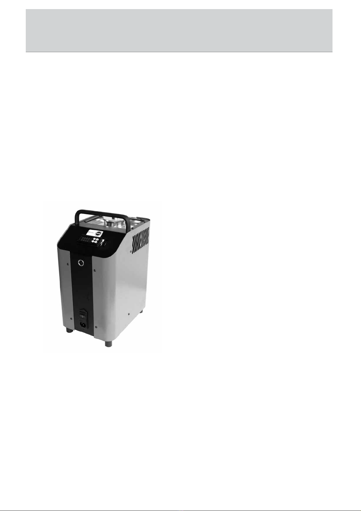
The Messko calibration bath is a portable unit for service tasks and is intended to inspect thermometers,
thermostats and resistance thermometers. The operational safety of the supplied instrument is only
guaranteed if it is operated according to his intended use (inspection of temperature sensors). Specified limit
values (see “Technical Data”) should never be exceeded.
It is your responsibility to select the instrument which is suitable for your specific application, to connect it
correctly, to carry out tests and to maintain all the components.
This operating manual applies only to the Messko calibration bath MZT1650S.
The Messko calibration bath consists of a robust, black and blue steel housing with an integrated carrying
handle.
The rear part of the housing contains a metal block/liquid bath with a hole, accessible from the top, for the
test specimen fixture.
The heating or cooling elements and the temperature sensor for determining the reference temperature are
integrated in the metal block / liquid bath.
The metal block / liquid bath is heat insulated.
Fig. 1:
Messko calibration bath MZT1650S
BA 2112/00/01 5
1 Device Description and Intended Use
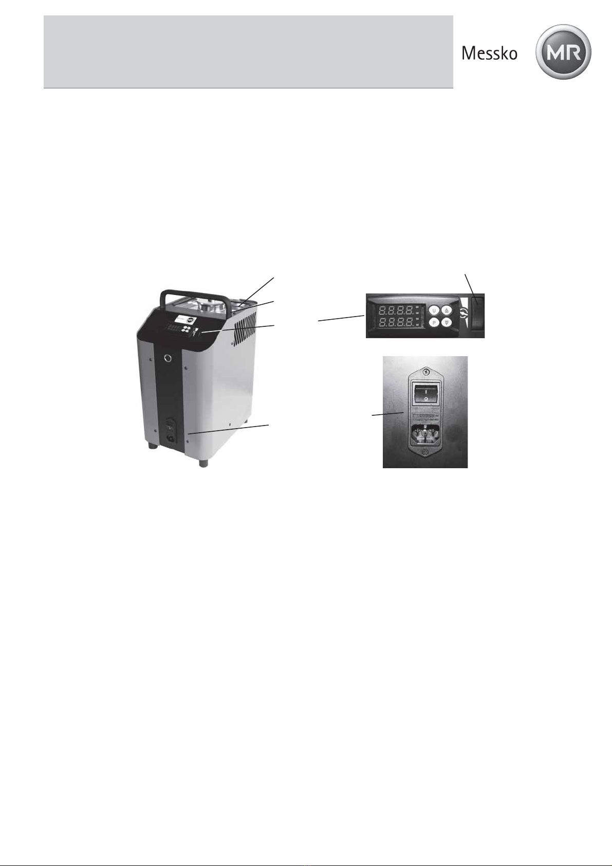
The front part of the housing contains the complete electronic unit for controlling the reference
temperature.
A controller equipped with a 7-segment LED (2 lines, 4 digits) for the reference and set temperature is
located on the front plate.
The Messko calibration bath also has a thumb wheel for controlling the stirring speed.
A power supply switch is located on the front of the housing. This is also where the IEC plug with fuse for
the mains supply can be found.
Fig. 2: Component overview
block
handle
controller
switch ON/OFF with fuse
power supply connection
wheel for controlling
the stirring speed

6 BA 2112/00/01
2 Safety Instructions
2 Safety Instructions
Always read the operating instructions carefully prior to using the new product. Always adhere to the
instructions contained herein, especially the safety instructions; otherwise, there is a potential risk of operator
injury and damage to the calibration bath and the sensors being tested.
Even though Messko provides assistance for the use of the product through personal consultation or the
respective documents, it is the responsibility of the customer to determine the suitability of the product for the
specific application.
The Messko calibration bath is a state-of-the-art device. This relates to the accuracy, functioning and the
safe operation of the calibration bath. However, professional and safety conscious conduct of the operator is
required to ensure safe operation.
2.1 Qualified personnel
The personnel entrusted with start-up, operation and maintenance of the calibration bath have to be
suitably qualified; the required knowledge can be gained via training courses or appropriate on-the-job
instruction. The personnel have to be familiar with the contents of these instructions, which have to be
available to them at all times.
The electrical connection should only be carried out by a fully qualified electrician.
All work has to be carried out in accordance with existing national regulations on accident prevention
and safety at work and with any internal regulations of the operator, even if they are not specified in
these instructions.
Always observe the safety information contained in these operating instructions.
2.2 Basic safety regulations
Only operate the calibration bath when it is in correct, fully functional condition.
The calibration bath is energized with hazardous voltages via a mains cable. Improper use can result
in personal injuries.
Correct and safe operation of the calibration bath demands correct transport, storage, installation and
assembly, as well as proper use and careful operation and maintenance.
The calibration bath should only be used for its intended purpose. Furthermore, hazardous media
should not be used and all technical specifications have to be observed.
If faults cannot be cleared, immediately shut down the calibration bath and ensure that it cannot be
started up accidentally.
Repairs should only be carried out by the manufacturer. Tampering with or modifying the calibration
bath is strictly prohibited.
Prior to replacing the safety fuse, always de-energize the calibration bath completely by disconnecting
the mains cable from the mains outlet.
Ensure that the complete operating instructions are always available in excellent condition at the
calibration bath installation site.
Ensure that calibration bath operators receive regular instruction in the various aspects of
occupational health and safety and environmental protection and have full knowledge of these
operating instructions and the safety information contained herein.
Thermal fuse
For protection purposes, the calibration bath is equipped with an autonomous thermal fuse, which
interrupts the power supply to the heater if the temperature exceeds a certain value inside the
housing. Once the metal bock / liquid bath has cooled down, the calibration bath has to be returned to
Messko for inspection.
The calibration bath has been designed as a measurement and control instrument. If the calibration
bath is used for purposes not expressly specified in these operating instructions, additional safety
measures have to be taken.

BA 2112/00/01 7
2 Safety Instructions
The calibration bath should NOT be used in explosive atmospheres without appropriate protection
(flammable or explosive atmospheres).
If malfunctioning of the calibration bath can result in personal injuries or damage to property, the
system has to be protected with additional electromechanical protective equipment.
2.3 Safety instructions for the application of calibration liquids
Calibration liquid silicone oil:
Only use the silicone oil specified in this manual.
Always read the safety data sheet supplied with the silicone oil before using it.
Always ensure adequate ventilation when working with silicone oil, since hazardous substances can
be released.
Prevent silicone oil from coming into contact with your eyes.
Since silicone oil is hygroscopic, always use the transport cover to close the calibration bath after use.
The transport cover is equipped with a safety valve. If the calibration bath is closed when warm,
impermissible pressure can build up. In order to prevent excess pressure which can destroy the liquid
bath, the safety valve is activated once the pressure reaches approx. 2.5 bar. This can result in hot
steam being released.
Risk of severe burns!
Prior to transport or contact with the metal block / liquid bath ensure that it has cooled down
sufficiently, otherwise there is a risk of severe burns caused by the metal block / liquid bath and the
test specimen.
If problems or questions arise, please contact Messko directly.

8 BA 2112/00/01
3 Unpacking and Inspecting the Delivery
3 Unpacking and Inspecting the Delivery
Unpack your calibration bath.
The calibration bath is delivered in special protective packaging. Keep this protective packaging for sending
the instrument for recalibration or repairs to the Messko.
Inspect the delivery first.
Standard delivery micro calibration bath:
- Calibration bath
- Transport cover
- Sensor cage
- Carrier for up to 5 sensors
- Magnetic stirrer
- Mains connection cable
- 1 liter silicone oil (10CS) (Messko Art. no. 649-000-001)
- Bilge pump
- Test certificate
- Operating Instructions
- Service and transport case
4 Description of the Controls
4.1 Front of the controller
1
2
3
4
5678
9
10
11
12
Fig. 3: Overview of the controls on the front of the controller
1 – P key
- Accessing the default set temperature
- Accessing menu items and parameters
- Confirming inputs
2 - key
- Reducing the setting values
- Selecting individual menu items
- Returning to the previous menu level

BA 2112/00/01 9
4 Description of the Controls
3 - key
- Increasing the setting values
- Selecting individual menu items
- Returning to the previous menu level
4 – U key
- Retrieving the saved set temperatures
5 - LED OUT 1
- Signals the status of the output for the temperature control
If the LED OUT 1 lights up, the calibration bath is heating
If the LED OUT 1 does not light up, the calibration bath is not heating
6 - LED OUT 2
Heating and cooling instrument
- Signals the status of the output for the temperature control
If the LED OUT 2 lights up, the calibration bath is cooling
If the LED OUT 2 does not light up, the calibration bath is not cooling
7 - LED OUT 3
- This LED has no function here
8 - LED OUT 4
- This LED has no function here
9 - LED SET
- When flashing, it signals access to the individual menu items and parameters
10 - LED AT/ST
- This LED has no function here
11 – Upper indicator
- Displays the current reference temperature
- Displays the individual modes, menu items and parameters
12 – Lower indicator
- Displays the set temperature
- Displays certain parameters in the individual modes and menu items

10 BA 2112/00/01
5 Start-up of the Calibration Bath
5 Start-up of the Calibration Bath
5.1 Operating position
The calibration bath has to be placed in a vertical standing position for operation. This position guarantees
optimum temperature distribution in the metal block / liquid bath.
5.2 Preparing the calibration bath
In order to achieve the best possible accuracy of a calibration bath, it has to be filled with a suitable
calibration liquid.
5.2.1 Characteristics of the calibration liquid
Different calibration liquids supply varying calibration results due to their specific characteristics. The Messko
calibration bath is adjusted on the silicon oil shown below.
We recommend the following calibration liquid for the specified temperature range:
Calibration Range Ignition
Temperature
Dow Corning 200
fluid with 10 CS -35°C 155°C 165°C
Only use the silicone oil specified in this manual.
Always read the safety data sheet supplied with the silicone oil before using it.
Always ensure adequate ventilation when working with silicone oil, since hazardous substances can
be released.
Prevent silicone oil from coming into contact with your eyes.
Since silicone oil is hygroscopic, always use the transport cover to close the calibration bath after use.
BA 2112/00/01 11
5 Start-up of the Calibration Bath
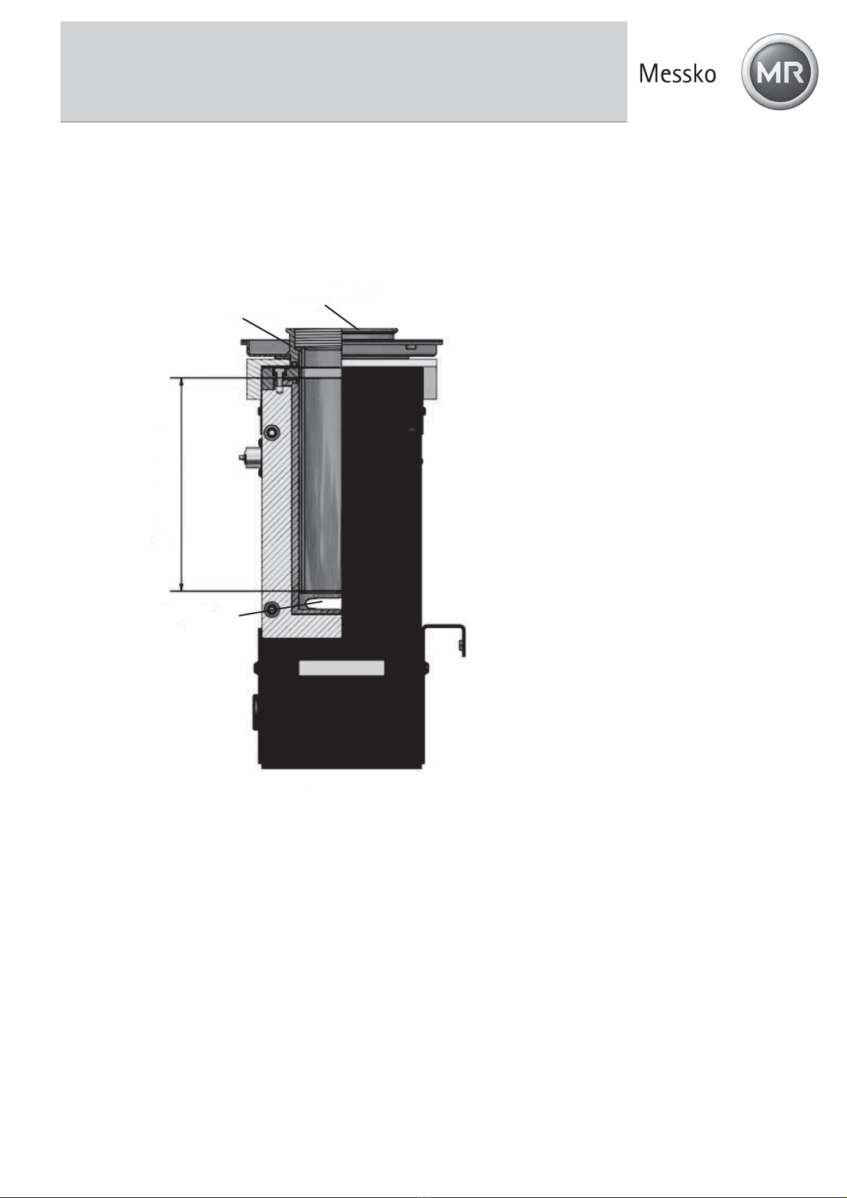
5.2.2 Filling the calibration bath
Remove the transport cover.
Insert the test specimen into the sensor cage.
Fill the tank with calibration liquid. The max. filling level in the tank is displayed by the upper edge of
the aluminium lining (see Fig. 4). The max. filling level is 0.5 litres.
Magnetic stirrer
Sensor cage Transport cover
Aluminium lining
lling level 150 mm
Fig. 4: Max. filling level of the liquid bath
Note:
The transport cover is equipped with a safety valve. If the calibration bath is closed when warm,
impermissible pressure can build up. In order to prevent excess pressure which can destroy the liquid bath,
the safety valve is activated once the pressure reaches approx. 2.5 bar. This can result in hot steam being
released.

12 BA 2112/00/01
5 Start-up of the Calibration Bath
5.2.3 Operating the magnetic stirrer
The best possible homogeneity is achieved by stirring the calibration liquid with the magnetic stirrer.
Set the stirring speed to the respective max. speed. Turn the thumb wheel (Fig. 6) upwards to
increase and downwards to decrease the stirring speed.
Fig. 5: Liquid bath Fig. 6: Front of the controller with stirring speed wheel
5.3 Testing temperature sensors
A separate temperature measuring instrument connected to the test specimen is required to test the
temperature sensors. By comparing the temperature displayed at the external measuring instrument with the
reference temperature it is possible to assess the status of the test specimen. Remember that the test
specimen requires a short period of time until it absorbs the temperature of the metal block or liquid bath.
Caution!
It is not possible to inspect earthed temperature sensors, because the heating block is earthed and any
measurement would produce incorrect results.
5.4 Start-up procedure
If the calibration bath is not used for a longer period, it is possible for moisture to enter the heating elements
due to the material used (magnesium oxide).
After calibration bath transport or storage in a damp environment, the heating elements have to be gently
brought up to operating temperature. During the drying out procedure it has to be assumed that the
calibration bath has not yet achieved the required insulation voltage for protection class I. The start-up set
value is Tstart=120°C for a stop period of th =15 min.
5.5 Switching on the calibration bath
Connect the supplied mains plug to a mains outlet.
Actuate the mains switch.
The controller is initialized
tESt appears on the upper display (red).
The version number, e.g. rL 2.2, appears on the lower display (green).
Initialization is completed after approx. 5 sec., the calibration mode is then automatically displayed.
The installed heating and cooling elements automatically adjust the metal block from the room temperature
to the set temperature set at the controller.
BA 2112/00/01 13
5 Start-up of the Calibration Bath
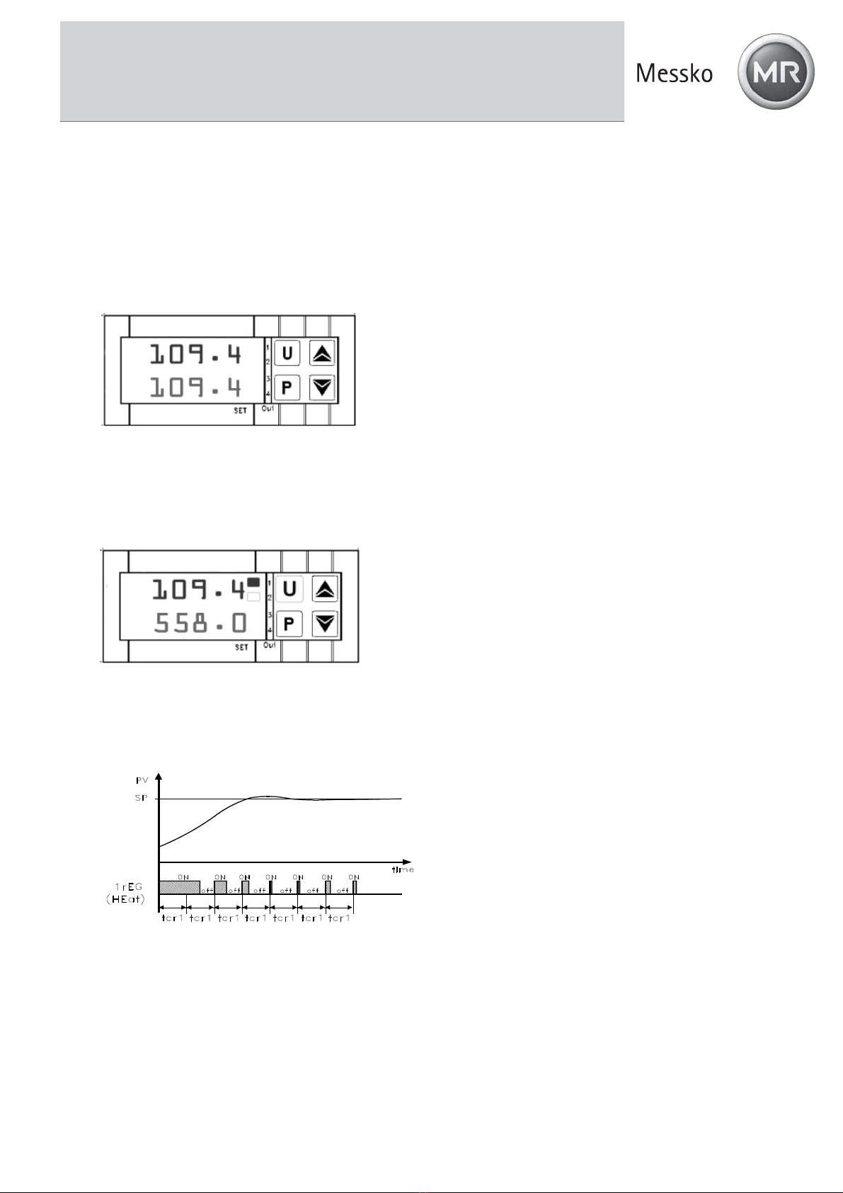
5.6 Reference and set temperature display
Upper display (red):
The red, 4-digit, 7-segment display shows the current temperature of the metal block / liquid bath.
Lower display (green):
The green, 4-digit, 7-segment display shows the current set temperature of the metal block / liquid bath.
Once the set temperature has been achieved, the radiated heat energy from the metal block / liquid bath is
supplied by short firing pulses, thus ensuring that the temperature inside is kept constant.
Fig. 7: Reference and set temperature display
5.7 Stabilizing the reference temperature
The switch on time of the heater is displayed by the red LED OUT 1.
Fig. 8: LED OUT 1 displays
During the heating up phase a constantly lit LED displays the supply of heat energy, a flashing LED indicates
that the reference temperature has almost reached the set temperature and the heat energy is now being
supplied at short intervals.
PV = current reference temperature
SP = set temperature
Fig. 9: Control occurs via PID algorithm
In order to guarantee excellent temperature stability, the cycle time of the controller is set to low and the
control output is addressed on a regular basis.

14 BA 2112/00/01
6 Operating the Calibration Bath
6 Operating the Calibration Bath
Three operating modes are available:
Calibration mode
This is the normal operating mode in which the inspection of test specimens is carried out.
Set value mode
The set temperatures can be entered in this mode.
Main menu
All the settings can be carried out in this mode, e.g. presetting the set temperatures or setting the
control parameters.
6.1 Calibration mode
The calibration bath is automatically in calibration mode as soon as it has been switched on and after
initialization.
The current reference temperature is displayed by the upper display (red).
The set temperature is displayed by the lower display (green).
The LED OUT 1 indicates the status of the output for the heater control:
If LED OUT 1 lights up, the temperature is being increased.
If LED OUT 1 does not light up, the heater is switched off.
Fig. 10: Calibration mode HEATING displays
The LED OUT 2 indicates the status of the output for the fan / cooling control:
Fig. 11: Calibration mode FAN or COOLING displays
The LED OUT 2 indicates the status of the output for the cooling control:
If LED OUT 2 lights up, the temperature is being decreased.
If LED OUT 2 does not light up, cooling is switched off.
There are two ways to set the set temperature: Either you set a temporary set temperature (see section 6.2)
or you save fixed set temperatures in the main menu (see section 6.3).

BA 2112/00/01 15
6 Operating the Calibration Bath
6.2 Setting a temporary set temperature (set value mode)
In this operating mode it is possible to temporarily modify a saved set temperature.
Press the P key.
The currently active set value memory, e.g. SP 2 (set point 2), is displayed by the upper display
(red).
The respective set temperature is displayed by the lower display (green).
Fig. 12: Temporary set temperature setting
Press the key to increase the set temperature.
Press the key to decrease the set temperature.
Press the Pkey again to confirm the new set value.
Note:
Press the and key to raise and lower the value by 0.1 respectively. If the keys are held pressed
for at least one second, the value increases or decreases quickly and after two seconds even more
quickly; this means the desired value can be reached rapidly.
If no key is pressed in the set value mode for approx. 15 seconds, the device automatically returns to
the calibration mode.

16 BA 2112/00/01
6 Operating the Calibration Bath
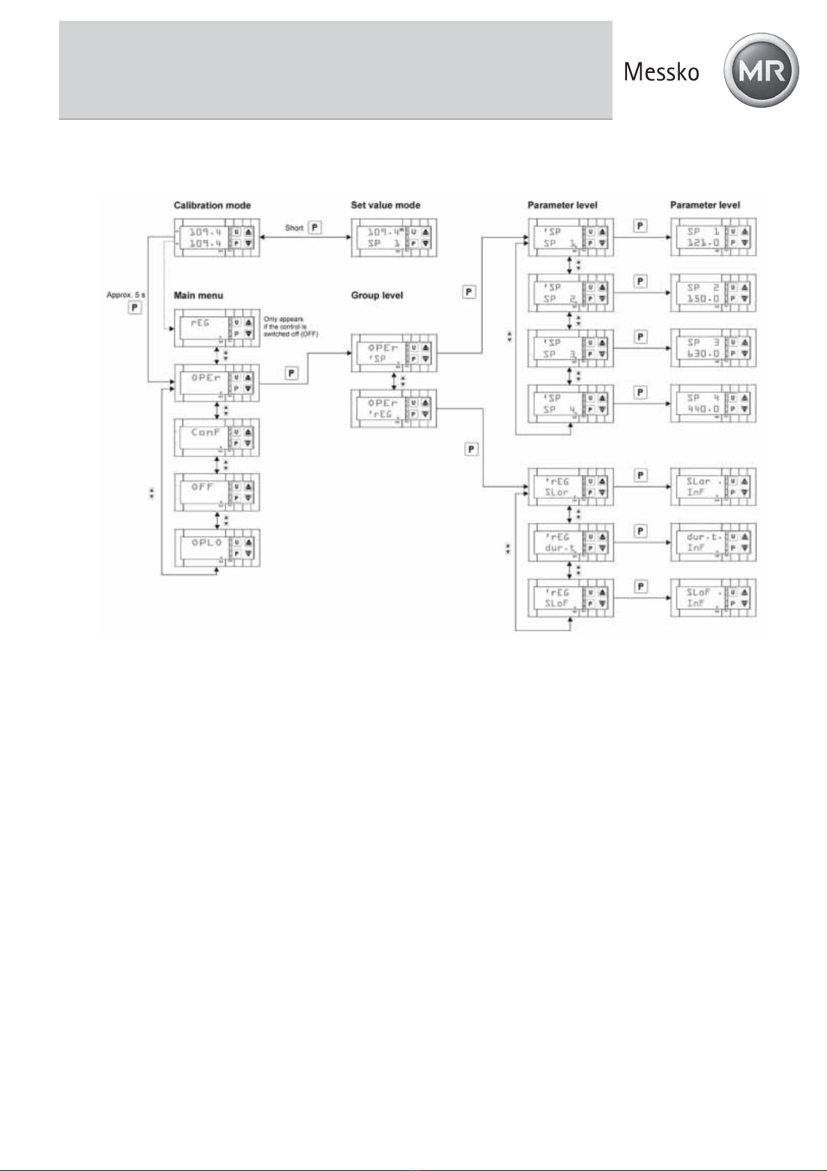
6.3 Programming (main menu)
All the settings can be carried out in this menu structure.
Press the Pkey for approx. 5 seconds. The main menu opens.
Use the and keys to select the desired main menu (see overview).
Press the Pkey to confirm the selected menu item.
Fig. 13: Menu structure (main menu)
BA 2112/00/01 17
6 Operating the Calibration Bath
As displayed by the menu structure, it is possible to reach the group and parameter levels to carry out
settings via OPEr.
Fig. 14: Menu structure at group and parameter level
Returning to another level
If no key is pressed in the main menu at the group or parameter level for approx. 15 seconds, the device
automatically returns to the previous level up to the calibration mode.
You can also return to a previous level by pressing and holding the or key.

18 BA 2112/00/01
6 Operating the Calibration Bath
6.3.1 Switching off the automatic control
For certain tasks it can be advantageous to switch off the control, e.g. to carry out settings at the calibration
bath.
Press the Pkey when in calibration mode for approx 5 sec., the main menu opens.
OPEr appears on the upper display (red)
LED SET flashes on the lower display (green).
Fig. 15: Main menu display
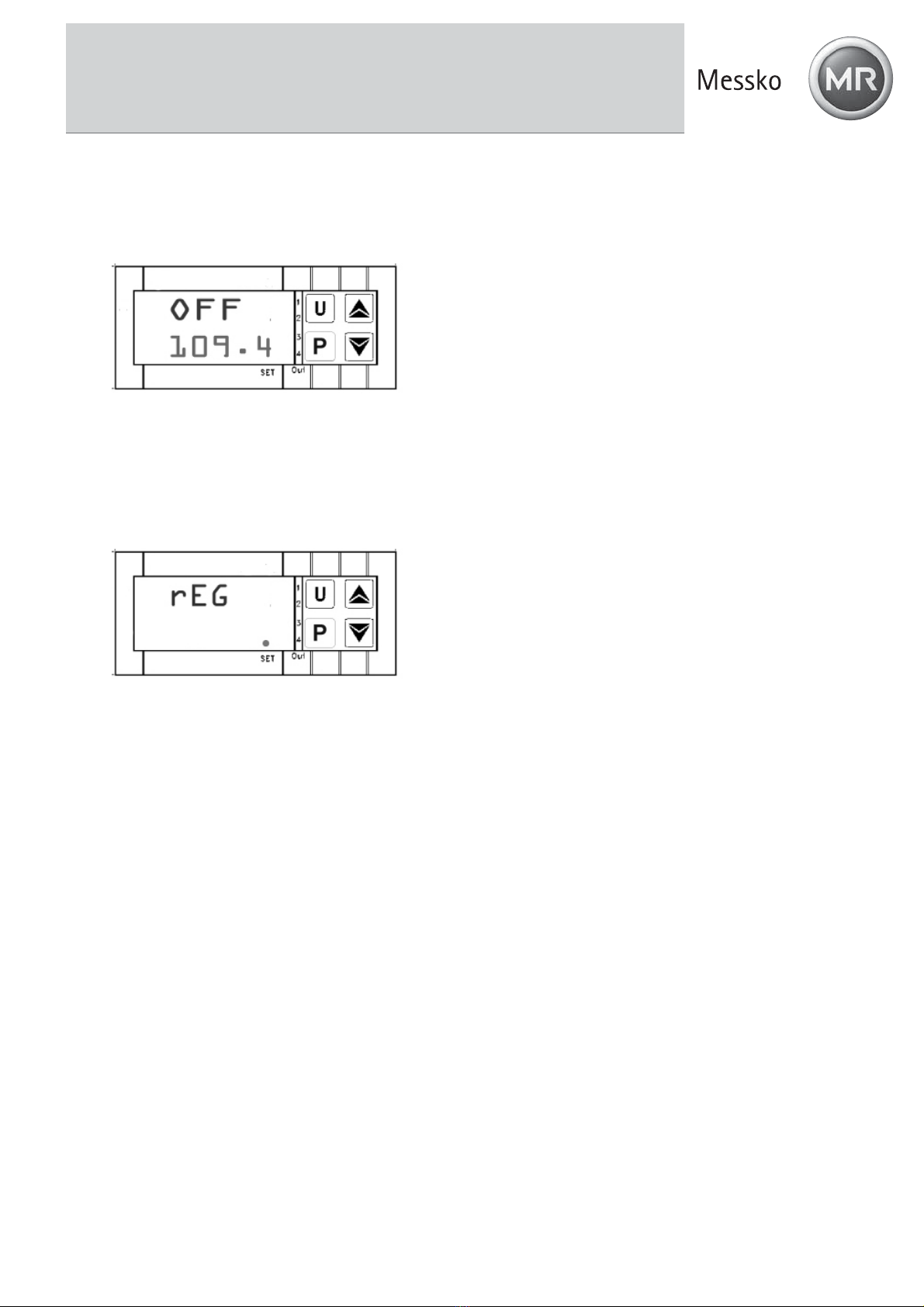
Press the or key until OFF appears.
Fig. 16: Menu control OFF
Press the P key to confirm.
An alternating display of the current reference temperature and OFF appears on the
upper display (red).
The current set temperature appears on the lower display (green).
Fig. 17: Control OFF setting display
Caution! The control has now been switched off and the reference temperature will constantly drop without
being regulated.
BA 2112/00/01 19
6 Operating the Calibration Bath
6.3.2 Switching on the automatic control
The control is switched off if the following display appears:
An alternating display of the current reference temperature and OFF appears on the upper display (red).
The current set temperature appears on the lower display (green).
Fig. 18: Control OFF setting display
Switch the control back on by:
Pressing the P key for approx. 5 sec., the main menu opens.
rEG appears on the upper display (red).
LED SET flashes on the lower display (green).
Fig. 19: rEG display
Press the Pkey to confirm switching on the control.
Caution! The control has been reactivated. The calibration bath is in calibration mode and the set
temperature is targeted.

20 BA 2112/00/01
6 Operating the Calibration Bath
6.3.3 Switching on the manual control
It is possible to switch off the automatic control of the calibration bath and to achieve the desired temperature
via manual control.
Press the Pkey for approx 5 sec., the main menu opens.
OPEr appears on the upper display (red).
LED SET flashes on the lower display (green).
Fig. 20: Main menu display
Press the or key until OPLO appears
OPLO appears on the upper display (red).
LED SET flashes on the lower display (green).
Fig. 21: Menu manual control OPLO
Press the P key to confirm.
The current reference temperature appears on the upper display (red).
The letter H and the currently set output capacity in % appear on the lower display (green).
Fig. 22: Manual control OPLO setting display
Press the key,to increase the output capacity.
Press the key,to decrease the output capacity.
Caution! Press the and key to raise and lower the value by 0.1 respectively. If the keys are held
pressed for at least one second, the value increases or decreases quickly and after two seconds even more
quickly; this means the desired value can be reached rapidly.
Table of contents
Popular Test Equipment manuals by other brands
![OXO [T]Box RDM User instruction](/data/manuals/1q/n/1qnxm/sources/oxo-t-box-rdm-manual.jpg "OXO [T]Box RDM User instruction")
OXO
OXO [T]Box RDM User instruction

Extech Instruments
Extech Instruments ET23B user manual

AFJ Instruments
AFJ Instruments FFT 3010 operating manual

Multimetrix
Multimetrix ERT 201 user manual

HIPOTRONICS
HIPOTRONICS OC-DI Series operating instructions

Würth
Würth 0715 53 07 Translation of the original operating instructions


