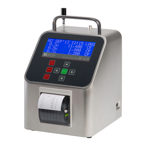
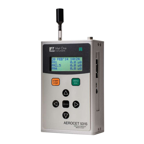
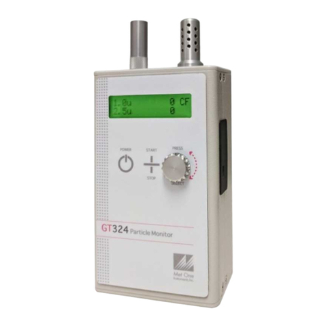
Met One Instruments GT-321 User manual

GT-321 HAND HELD
PARTICLE COUNTER
OPERATION MANUAL
GT-321-9800 Rev D.doc
AC Tool Supply
877-207-1244
www.aikencolon.com

Copyright Notice
Model GT-321 Hand Held Particle Counter Operation Manual
© Copyright 2001 Met One Instruments, Inc. All Rights Reserved Worldwide.
No part of this publication may be reproduced, transmitted, transcribed, stored in a
retrieval system, or translated into any other language in any form by any means
without the express written permission of Met One Instruments, Inc.
Technical Support
Should you require support, please consult your printed documentation to resolve your
problem. If you are still experiencing difficulty, you may contact a Technical Service
representative during normal business hours—7:30 a.m. to 4:00 p.m. Pacific Standard
Time, Monday through Friday.
Mail: Technical Services Department
Met One Instruments, Inc.
1600 Washington Boulevard
Grants Pass, OR 97526
Page 2 of 18 GT-321 Operation Manual GT-321-9800 Rev D.doc
AC Tool Supply
877-207-1244
www.aikencolon.com

Safety Notice
The contents of this manual have been checked against the hardware and software
described herein. Since deviations cannot be prevented entirely, we cannot guarantee
full agreement. However, the data in this manual is reviewed regularly and any
necessary corrections included in subsequent editions.
Faultless and safe operation of the product presupposes proper transportation, storage,
erection and installation as well as careful operation and maintenance. The seller of
this equipment cannot foresee all possible modes of operation in which the user may
attempt to utilize this instrumentation.
The user assumes all liability associated with the use of this instrumentation. The seller
further disclaims any responsibility for consequential damages.
NOTICE
CAUTION—Use of controls or adjustments or performance of
procedures other than those specified herein may result in
hazardous radiation exposure.
WARNING—This product, when properly installed and operated, is
considered a Class I laser product. Class I products are not
considered to be hazardous.
There are no user serviceable parts located inside the cover of this device.
Do not attempt to remove the cover of this product. Failure to comply with this
instruction could cause accidental exposure to laser radiation.
This system contains a laser operating at 850 nm. This wavelength is invisible to the
naked eye and can cause damage to the eye if directly exposed. A protective housing
protects the unit. To avoid the possibility of accidental exposure, always power down
the system any time service or repair work is being preformed.
Repair of instrumentation manufactured by Met One Instruments, Inc. should only be
attempted by manufacturer trained service personnel.
GT-321-9800 Rev D.doc GT-321 Operation Manual Page 3 of 18
AC Tool Supply
877-207-1244
www.aikencolon.com

Electrical & Safety Conformity
The manufacturer certifies that this product operates in compliance with the following
standards and regulations:
•FDA / CDRH This product is tested and complies with 21 CFR, Subchapter J, of
the health and Safety Act of 1968.
•European Community (CE) Directive 89/336/EEC
EN 55011 Group 1, Class B (Emissions) and EN 55082-1 (Immunity)
•IEC 60825-1 Ed.1.1 (1998-01)
•EN 60825-1 W/A11 (1996)
•US 21 CFR 1040.10
Warranty
Products manufactured by Met One Instruments, Inc. are warranted against defects in
materials and workmanship for a period of (1) year from the date of shipment from the
factory. Offered products not manufactured by Met One Instruments, Inc. will be
warranted to the extent and in the manner warranted by the manufacturer of that
product.
Any product found to be defective during the warranty period will, at the expense of Met
One Instruments, Inc. be replaced or repaired and return freight prepaid. In no case
shall the liability of Met One Instruments, Inc. exceed the purchase price of the product.
This warranty may not apply to products that have been subject to misuse, negligence,
accident, acts of nature or that have or modified other than by Met One Instruments,
Inc. Consumable items such as bearings are not covered under this warranty.
Other than the warranty set forth herein, there shall be no other warranties, weather
expressed, implied or statutory, including warranties of fitness or merchantability.
Page 4 of 18 GT-321 Operation Manual GT-321-9800 Rev D.doc
AC Tool Supply
877-207-1244
www.aikencolon.com

Table of Contents
1. Safety..................................................................................................................... 6
1.1. Safety Indicators........................................................................................................................6
2. Setting Up.............................................................................................................. 7
2.1. Unpacking..................................................................................................................................7
2.2. Familiarization ...........................................................................................................................8
2.3. Test Run....................................................................................................................................9
3. GT-321 Overview................................................................................................... 9
3.1. Description.................................................................................................................................9
3.2. Applications .............................................................................................................................10
3.3. Certifications............................................................................................................................10
4. Operation............................................................................................................. 11
4.1. Iso-kinetic Sampling ................................................................................................................11
4.2. Taking a Sample......................................................................................................................11
5. Maintenance ........................................................................................................ 12
5.1. Service Schedule.....................................................................................................................12
5.2. Service Schedule Table...........................................................................................................12
5.3. Battery Pack ............................................................................................................................13
5.4. Zero Test .................................................................................................................................13
5.5. Flow Rate Test ........................................................................................................................14
5.6. Display Contrast Adjust...........................................................................................................14
6. Troubleshooting.................................................................................................. 15
7. Serial Communication Protocol......................................................................... 16
8. Specifications...................................................................................................... 17
GT-321-9800 Rev D.doc GT-321 Operation Manual Page 5 of 18
AC Tool Supply
877-207-1244
www.aikencolon.com

1. Safety
1.1. Safety Indicators
This manual uses a CAUTION and a WARNING indication.
Familiarize yourself with the following definitions for the meanings of these indicators.
A CAUTION indicates a hazard and calls attention to a procedure that if not correctly
followed could result in damage to the instrument. Do not proceed beyond a caution
indicator without understanding the hazard.
A WARNING indicates a hazard to you and calls attention to a procedure that if no
correctly followed could result in injury or even death. Do not proceed beyond a warning
without understanding the hazard.
Page 6 of 18 GT-321 Operation Manual GT-321-9800 Rev D.doc
AC Tool Supply
877-207-1244
www.aikencolon.com

2. Setting Up
2.1. Unpacking
When you unpack the GT-321 and accessories, inspect the carton for obvious damage.
If the carton is damaged notify the carrier. Unpack everything and make a visual
inspection.
You should have the following:
1. Carrying case
2. GT-321 Hand Held Particle Counter
3. Miniature screwdriver
4. Iso-kinetic Sample Probe with a short piece of tubing
5. Zero Particulate Filter (Met One Part Number G3111)
6. Universal AC to DC converter module with IEC AC power cord
7. RS-232 Serial Cable
8. Operation Manual
9. GT-321 Calibration Certificate
10.Color Brochure (optional)
If any of the above components are missing contact your supplier.
Keep the carton and packing material for reuse.
GT-321-9800 Rev D.doc GT-321 Operation Manual Page 7 of 18
AC Tool Supply
877-207-1244
www.aikencolon.com

2.2. Familiarization
Item Description
Power Switch Used to turn ON and OFF power to the unit.
Charging Jack Plug Universal AC to DC converter module into the jack to charge
the batteries.
Iso-kinetic Filter Reduces count errors due to mismatched sample flow velocity.
Display Adjust Adjusts the LCD display contrast (Section 5.6).
Flow Adjust Adjusts the flow rate of the unit (Section 5.5).
Serial Port Can be used to access internal commands (Section 7).
Page 8 of 18 GT-321 Operation Manual GT-321-9800 Rev D.doc
AC Tool Supply
877-207-1244
www.aikencolon.com

2.3. Test Run
The battery pack inside the GT-321 should be charged for 15 hours prior to use (see
section 5.3 – Battery Pack). Once the battery pack is fully charged, remove the rubber
cap from the GT-321 inlet nozzle. The inlet nozzle protrudes from a hole in the top of
the GT-321 case.
Next, turn on the power switch that is located on the left side. The LCD display on the
GT-321 will indicate 0.3u. If there is no display or a dim display the LCD contrast may
require adjustment (see section 5.6).
Press the <SELECT> key several times and note that the display sequences through
the particle size selections of 0.3u, 0.5u, 1.0u, 2.0u, and 5.0u. Select the 0.3u size,
then hold the GT-321 with the inlet nozzle pointing upward.
Finally, press the <START> key. You should hear the internal vacuum pump start
running. After 9 seconds (subsequent readings every 6 seconds) a number will appear
on the display representing the number of particles per cubic foot larger than 0.3µm.
If the sample was taken in a relatively clean area the count may be as low as 200,000
whereas in a dusty area it could be as high as 3,000,000. The GT-321 will continue to
take 9 more 6-second samples. The results from the 10 samples are then averaged and
displayed.
This finishes the test run. Always remember to turn the power off when not in use to
conserve battery power.
The GT-321 is now checked out and ready for use, however, you should read the rest of
this manual to better understand how to use and maintain this instrument.
3. GT-321 Overview
3.1. Description
The GT-321 is designed to be a small, easy to use and completely portable hand-held
particle counter that can provide fast and accurate measurement of particulate
contamination in particles per cubic foot. The GT-321 has 5 selectable size ranges of
0.3, 0.5, 1, 2, and 5 micron.
The GT-321 contains a laser diode based sensor, NiCd battery pack, vacuum pump,
microprocessor electronics, LCD display and user input keys all in one small package.
The accuracy of the GT-321 is certified according to ASTM and JIS standards and
comparable to larger more expensive bench top particle counters. The fast 6-second
response of the GT-321 makes it especially useful for troubleshooting contamination
problems and tracing contamination leaks to the source.
The laser diode based sensor inside the GT-321 utilizes a specially designed elliptical
mirror for high light collection efficiency and improved signal to noise. Precision optics
GT-321-9800 Rev D.doc GT-321 Operation Manual Page 9 of 18
AC Tool Supply
877-207-1244
www.aikencolon.com

collimate the laser beam into a thin, very intense beam resulting in increased signal and
a high concentration limit of 3,000,000 particles per cubic foot. This high concentration
limit allows the GT-321 to be used for indoor and outdoor aerosol particulate
measurement.
3.2. Applications
•Controlled Environments
•Indoor Air Quality Studies
•Process Control
•Ventilation Systems
•Filter Testing
•Laboratory and Manufacturing Environments
•Concerned citizen groups that want to do their own air quality studies
•Hospitals and nursing homes
•Efficiency testing of residential air purifiers
•Emissions Sourcing
3.3. Certifications and Compliance
•CE Certified
•NIST traceable calibration in accordance with JIS B 9921 and ASTM F328 and
ASTM F649
•In accordance with ISO 14644-1:1999(E) and ISO 14644-2:2000(E)
Page 10 of 18 GT-321 Operation Manual GT-321-9800 Rev D.doc
AC Tool Supply
877-207-1244
www.aikencolon.com

4. Operation
4.1. Iso-kinetic Sampling
The GT-321 comes with an iso-kinetic probe that attaches to its inlet nozzle with the
short piece of Tygon tubing provided. Attach the other end of the tubing to the GT-321
inlet nozzle (See section 2.2 Familiarization).
The iso-kinetic probe helps reduce count errors related to the sample flow velocity and
the aerodynamics of small particles. The iso-kinetic probe should be used for most
sampling applications. When taking a sample of typical indoor or outdoor aerosols the
opening of the iso-kinetic probe should always face upward. The GT-321 can be held in
your hand or placed on a flat surface with its display facing towards you.
When sampling in an area having constant airflow, such as a clean room, duct, vent or
the downstream side of a filter, always face the opening of the iso-kinetic probe into the
air flow. The length of the connecting tubing going from the inlet on the GT-321 to the
iso-kinetic probe can be increased if necessary but count losses, especially for larger
particles, will become a problem after approximately a four-foot length. Try to keep the
tubing length short.
The sampling height will affect the GT-321 particle count reading. Taking a sample near
the floor can give results several times higher than a sample taken at eye level.
When using the GT-321 to find the source of a contamination problem, be aware that
not all contamination problems are continuous, some are the result of a short-term
event or burst of particles. Locating the source will require taking a number of samples
in the same spot.
4.2. Taking a Sample
CAUTION: Never sample smoke, paint spray, oil mist, reactive, or pressurized
gasses to avoid damaging the sensor optics.
Remove the rubber cap from the GT-321 aerosol inlet nozzle and attach the Iso-kinetic
probe. Turn the GT-321 power switch on. Press the <SELECT> key and select the
particle size range of interest.
When you select a particle size, you are setting a lower size limit for the counter in the
GT-321. The industry standard setting for a particle counters size selection is 50%
counting efficiency. This means that the GT-321 will count ½ of the particles of the
selected size when a sample is taken. Counting efficiency increases rapidly to 100% for
particles larger than the selected size. All particles larger than the selected size are
counted. This type of counting is defined as cumulative counting.
After selecting a particle size, press the <START> key. You will hear the pump inside
the GT-321 activate. After 9 seconds the first sample result in particles per cubic foot is
displayed. The GT-321 will automatically take a series of 10 samples; each sample after
the initial sample that includes 3 seconds of warm-up time for the internal pump takes 6
seconds. The display will update every 6 seconds with the new result. After all 10
GT-321-9800 Rev D.doc GT-321 Operation Manual Page 11 of 18
AC Tool Supply
877-207-1244
www.aikencolon.com

samples are taken the GT-321 averages the results of the 10 samples for a more
accurate result. The display will hold the average result until the start key is pressed to
take another sample or until the unit is switched off. The <STOP> key is used to stop a
sample at anytime.
Any data accumulated is lost when the <STOP> key is pushed.
5. Maintenance
5.1. Service Schedule
WARNING: There are no user serviceable components inside this instrument. The
covers on this instrument should not be removed or opened for servicing, calibration or
any other purpose except by a factory-authorized person. To do so may result in
exposure to invisible laser radiation that can cause blindness.
Sensor, vacuum pump and filter replacement requires access to the inside of the GT-
321 and a factory-authorized person must do this. Contact Met One Instruments for
service information.
Calibrating particle sensors like the one in the GT-321 requires specialized equipment
and a skilled technician. Met One Instruments, Inc. maintains a calibration facility for
calibrating particle counters according to industry-accepted methods like ASTM and JIS
using NIST traceable standards. The sensor in the GT-321 should be calibrated on a
yearly basis.
5.2. Service Schedule Table
Item To Service Frequency Done By
Zero test Weekly Customer or Factory Service
Flow rate test Monthly Customer or Factory Service
Inspect internal filter Yearly Factory service only
Inspect pump Yearly Factory service only
Test battery pack Yearly Factory service only
Calibrate Sensor Yearly Factory service only
Page 12 of 18 GT-321 Operation Manual GT-321-9800 Rev D.doc
AC Tool Supply
877-207-1244
www.aikencolon.com

5.3. Battery Pack
CAUTION: There are no user serviceable components inside the GT-321. Do not
attempt to change the internal battery pack. The wrong battery pack could cause
serious damage or a fire. The GT-321 should be sent to a service center where a
factory qualified person would change and properly dispose of the battery pack.
When the battery is low enough to need charging, a “Battery Low” message is displayed
on the display and the pump will not turn on when the <START> key is pushed.
To charge the battery pack, connect the AC power cord from the AC to DC converter
module to an AC power outlet. The module is universal and will work with power line
voltages of 100 to 240 volts, 50 to 60 Hz. Take the plug on the end of the cord coming
from the converter module and plug it into the charger input socket on the side of the
GT-321 just below the power switch (See section 2.2 Familiarization). To fully charge a
discharged battery pack may take up to 15 hours.
The battery pack inside the GT-321 when fully charged will power the GT-321 for about
five hours of continuous use. Under normal intermittent or manual operation however,
there is considerably less battery drain and up to 10 hours of use is possible.
If the GT-321 is to be used powered by its battery pack on a daily basis, connect the
charger after each day of usage. It will not damage the battery pack to leave it
connected to the charger for long periods.
When the GT-321 is always used in an area where AC power is available. Leave the
charger connected to the GT-321.
If the GT-321 is to be stored, fully charge the battery pack first. Storing a discharged
NiCd battery for any length of time will degrade its performance.
5.4. Zero Test
False counts caused by air leaks or spurious noise will cause errors, especially when
sampling relatively clean aerosols. A zero count test is easy to do.
Attach the zero test filter (Met One Part Number G3111) to the GT-321 inlet nozzle. The
zero filter removes 99.99% of all particles larger than 0.3 micron. The zero filter must be
large enough that it does not create a restriction and load down the small vacuum pump
inside the GT-321. Since the air passing through the GT-321 is now virtually particle
free, the output should be zero.
Select the 0.3 micron range on the GT-321 and take a sample. The result of the 1-
minute sample should be zero counts. If it does not read zero it is probably due to a leak
in the flow path inside the GT-321 or the zero filter is bad. If it is determined that there is
a leak, the GT-321 must be sent back to the factory for repair.
GT-321-9800 Rev D.doc GT-321 Operation Manual Page 13 of 18
AC Tool Supply
877-207-1244
www.aikencolon.com

5.5. Flow Rate Test
The sample flow rate of 0.1cfm is set at the factory. However, wear from continued use
will degrade the motor and vacuum pump. Variation in the flow rate will reduce the
accuracy of the instrument.
Testing the flow rate is an easy procedure. It requires a flow meter that is ±3% accurate
at 0.1cfm. The flow meter must be non-loading (low restriction). The tiny vacuum pump
inside the GT-321 can be easily loaded down by even a small restriction. Most hot wire
and differential pressure types of flow meters are non-loading.
To test the flow rate, connect the flow meter to the sample inlet nozzle of the GT-321
using a short piece of flexible 1/8“ (3 mm) ID tubing, Tygon tubing is a good choice.
Turn on the GT-321 and note the flow meter reading. The flow rate should be 0.10cfm
±5%.
The flow rate can be adjusted by a trim pot located in one of the two access holes in the
bottom of the GT-321 case (See section 2.2 Familiarization). Use the small screwdriver
that came with the GT-321 to make the adjustment. Turn the adjustment pot clockwise
to increase the flow and counter-clockwise to decrease the flow.
5.6. Display Contrast Adjust
A characteristic of LCD display is that their contrast is affected by temperature. Use the
small screwdriver provided to make the adjustment. The location of the Display
Adjustment is shown in section 2.2 Familiarization. Turn the adjustment pot to obtain the
desired contrast.
Page 14 of 18 GT-321 Operation Manual GT-321-9800 Rev D.doc
AC Tool Supply
877-207-1244
www.aikencolon.com

6. Troubleshooting
WARNING: There are no user serviceable components inside this instrument. The
covers on this instrument should not be removed or opened for servicing, calibration or
any other purpose except by a factory-authorized person. To do so may result in
exposure to invisible laser radiation that can cause blindness.
A factory-authorized person should do replacement of the sensor, vacuum pump, filter
or any component inside the GT-321.
Symptom Possible Cause Correction
Does not turn on, no
display 1. Low battery
2. Defective Battery 1. Charge battery 10 hrs
2. Send to service center
Display turns on but
pump does not 1. Low Battery
2. Defective pump 1. Charge battery 10 hrs
2. Send to service center
Keypad functions do not
Work Loose connector or
defective component
inside
Send to service center
Sample result remains
at zero after sampling 1. Pump stopped
2. Laser diode bad 1. Send to service center
2. Send to service center
Sample result is lower
than normal
1. Flow rate is low
2. Something may be
stuck in the inlet
nozzle and blocking
the beam
3. Contaminated optics
in sensor
1. Check flow rate
2. Blow into nozzle with a
can of ‘Aero Duster’. Do
not put any object down
into the nozzle
3. Send to service center
Sample result is higher
than normal 1. Air leak in sensor
2. Noisy laser 1. Send to service center
2. Send to service center
Battery pack does not
hold a charge
1. Defective or worn out
battery pack
2. Defective power
cords
3. Defective charger
module or chords
1. Send to service center
2. Check with an Ohm-
meter
3. Contact your distributor
to get another charger
GT-321-9800 Rev D.doc GT-321 Operation Manual Page 15 of 18
AC Tool Supply
877-207-1244
www.aikencolon.com

7. Serial Communication Protocol
The GT-321 serial communication protocol supports real time data acquisition using a basic
terminal program such as HyperTerminal.
Communication port setting = 9600 baud, 8 data bits, no parity and one stop bit.
Serial Commands – [ASCII Character(s)]:
0 = Start Counting
Start a one minute count cycle.
1 = Change Size Range
The GT-321 displays five different size ranges. The Change Size Range command is used to
select the next size range. This command is equivalent to pressing the Select Key.
3 = Change Count Units
Toggle between Counts per Cubic Foot (CF) and Counts per Liter (/L).
D0<Enter> = Disable Automatic Records
Do not output a record after each count cycle.
D1<Enter> = Enable Automatic Records
Output a record after each count cycle.
L = Send last record
Output the data from the last count cycle.
? = Display Commands
Output the help menu.
Example Record (CSV – Comma Separated Variable):
SIZE1,COUNT1,SIZE2,COUNT2<LF>
SIZE1 = Channel one size - fixed size (Note 2)
COUNT1 = Channel one count
SIZE2 = Channel two size - selectable size (Note 3)
COUNT2 = Channel two count
<LF> = Line feed
Notes:
1) The GT-321 will display one size range, but the unit actually has two count channels.
2) Channel one size (SIZE1) is fixed at the smallest size (normally 0.3 microns).
3) Channel two size (SIZE2) is selectable using the Select Key or the Change Size Command.
The standard sizes are 0.5, 1.0, 2.0 and 5.0 microns. SIZE2 will default to 0.5microns when
the channel one size (0.3u) is selected.
Page 16 of 18 GT-321 Operation Manual GT-321-9800 Rev D.doc
AC Tool Supply
877-207-1244
www.aikencolon.com

8. Specifications
Measuring principle Particle counter, light scatter
Light Source Laser Diode, 40 mW, 850 nm
Measurement ranges 0.3, 0.5, 1, 2, 5 micron size ranges
Accuracy ±10%, to calibration aerosol
Sensitivity 0.3µm = 2 to 1 peak to valley (JIS), 2 to 1 S/N
Concentration limit 3,000,000 particles per cubic foot
Measurement time 6 seconds, 1 minute
Flow rate 0.10 cfm (2.831 lpm)
Display 16 character LCD
Power 6 V NiCd battery pack
Charger AC to DC module, 9 V, 350 mA
Operating Temperature 0° to 50° C
Storage Temperature -20° C to +60° C
Size L 15.9 cm, W 9.3 cm, D 6.25 cm
Weight 0.79 kg, 28 ounces
Supplied accessories Operation Manual, Serial Cable, Universal AC
to DC Converter Module with AC Power Cord,
Iso-kinetic SampleProbe, Screwdriver, Case,
Zero test filter (Met One Part Number G3111)
GT-321-9800 Rev D.doc GT-321 Operation Manual Page 17 of 18
AC Tool Supply
877-207-1244
www.aikencolon.com

Declaration of Conformity
CE MARKING
Manufacturers Name: Met One Instruments, Inc.
Declares, that the product(s):
Product Names:
Particulate Monitor, Aerosol Mass Monitor, Particle
Counter
Model Numbers:
GT-321, GT-321-1, GT-331, GT-521
Product Options:
All
Are in compliance with the following documents:
EMC:
Emissions: CISPR 11:1990 / EN 61326-1
Immunity: EN50082-1 / EN 61326-1
Tom Pottberg
President
January 26, 1999
Met One Instruments, Inc
1600 NW Washington Blvd.
Grants Pass, Oregon 97526
Page 18 of 18 GT-321 Operation Manual GT-321-9800 Rev D.doc
AC Tool Supply
877-207-1244
www.aikencolon.com
Table of contents
Other Met One Instruments Cash Counter manuals

Met One Instruments
Met One Instruments AEROCET 531S User manual

Met One Instruments
Met One Instruments GT-324 User manual

Met One Instruments
Met One Instruments AEROCET 532 User manual

Met One Instruments
Met One Instruments 804 User manual

Met One Instruments
Met One Instruments AEROCET 532 User manual

Met One Instruments
Met One Instruments GT-526S User manual

Met One Instruments
Met One Instruments AEROCET 531S User manual

Met One Instruments
Met One Instruments AEROCET 831 User manual

Met One Instruments
Met One Instruments BT-610 User manual

Met One Instruments
Met One Instruments GT-521S User manual