TSUJI ELECTRONICS NCT08-02 User manual

E-mail info2@tsuji-denshi.co.jp
Ibaraki-Pre 300-0013 Japan
Phone +81-(0)29-832-3031
Fax +81-(0)29-832-2662
URL http://www.tsujicon.co.jp
APPLICATION OF ELECTRONIC DEVICES
TSUJI ELECTRONICS CO.,LTD
3739 Kandatsu-machi Tsuchiura-city
8CH COUNTER/TIMER
NCT08-02
USER'S MANUAL
2766 (rev 3.)

NCT08-02 COMMAND TABLE (To: LAN, USB)
COMMANDS CONTENTS OF COMMANDS DETAILES OF COMMANDS
ALM? alarm read inquiry the contents of overflow
CLAL clear all clear timer and 8 channel counters
CLPC clear preset counter clear preset counter (CH7)
CLTM clear timer clear timer
CLCTxx clear counter xx clear counter channel xx xx:00-07
CLCTxxyy clear counter xx to yy clear counter channel xx to yy xx、yy:00-07
CPR? counter preset data read read preset count value
reply 8 digit number in decimal (unit Kcts)
(example:00010000)
CPRF? counter preset data read read preset count value
reply 8 digit number in decimal (unit cts)
(example:00010000)
CTR?xx counter xx read read channel xx count value xx:00-07
reply 10 digit number in decimal
CTR?xxyy counter xx to yy read read channel xx to yy count value xx、yy:00-07
reply 10 digit number in decimal
space separated data
DSAS disable auto stop disable to automatically stop
(It means count on until STOP command)
ENCS enable counter stop enable to counter stop
ENTS enable timer stop enable to timer stop
MOD? mode read inquiry the mode
RDAL? read all counter and timer read all counter and timer
SCPRdddd・・・・ set counter preset data set preset data to counter (unit Kcts)
SCPRFdddd・・・・ set counter preset data set preset data to counter (unit cts)
TPR? timer preset data read read preset timer data (unit ms)
TPRF? timer preset data read read preset timer data (unit μs)
STOP stop counter deactivate counting action
STPRdddd・・・・ set preset counter to dddd・・・・ set preset timer value (unit ms)
STPRFdddd・・・・ set preset counter to dddd・・・・ set preset timer value (unit μs)
STRT start counter start counting action
TMR? timer read read timer value
VER? version information read read firmware version information
REST reset and start set the unit restart (It's same as power on sequence)
FROM? using ROM number read read program ROM number inside
FROM0,FROM1 choose ROM set program ROM number to activate
It's valid after RESET or power on sequence.
FLG?x read internal flag read internal state flag inside
1/15

CONTENTS
1.Specifications ・・・・・・・・・・・・・・・・・・・・・・・・・・・・・・・・・・・・・・・・・・・・・・・・・・・・・・・・・・・・・・・・・・ 3
1-1.Abstract ・・・・・・・・・・・・・・・・・・・・・・・・・・・・・・・・・・・・・・・・・・・・・・・・・・・・・・・・・・・・・ 3
・・・・・・・・・・・・・・・・・・・・・・・・・・・・・・・・・・・・・・・・・・・・・・・・・・・・・・・・
・
3
・・・・・・・・・・・・・・・・・・・・・・・・・・・・・・・・・・・・・・・・・・・・・・・・・・・・・・・・
・
4
2.Before using ・・・・・・・・・・・・・・・・・・・・・・・・・・・・・・・・・・・・・・・・・・・・・・・・・・・・・・・・・・・・・・・・・・ 4
・・・・・・・・・・・・・・・・・・・・・・・・・・・・・・・・・・・・・
・
4
・・・・・・・・・・・・・・・・・・・・・・・・・・・・・・・・・・・・・
・
4
・・・・・・・・・・・・・・・・・・・・・・・・・・・・・・・・・・・・・
・
4
・・・・・・・・・・・・・・・・・・・・・・・・・・・・ 5
・・・・・・・・・・・・・・・・・・・・・・・・・・・・ 7
・・・・・・・・・・・・・・・・・・・・・・・・・・・・・・・・・・・・・・・・・・・・・・・ 7
・・・・・・・・・・・・・・・・・・・・・・・・・・・・・・・・・・・・・
・
7
・・・・・・・・・・・・・・・・・・・・・・・・・・・・・・・・・・・・・
・
7
・・・・・・・・・・・・・・・・・・・・・・・・・・・・・・・・・・・・・
・
7
・・・・・・・・・・・・・・・・・・・・・・・・・・・・・・・・・・・・・
・
7
・・・・・・・・・・・・・・・・・・・・・・・・・・・・・・・・・・・・・
・
7
・・・・・・・・・・・・・・・・・・・・・・・・・・・・・・・・・・・・・
・
8
2-4-3.Start signal (TTL positive logic) ・・・・・・・・・・・・・・・・・・・・・・・・・・・・・・・・・・・・・
・
8
2-4-4.Stop signal (TTL positive logic) ・・・・・・・・・・・・・・・・・・・・・・・・・・・・・・・・・・・・・
・
8
2-4-5.Gate signal (TTL positive logic) ・・・・・・・・・・・・・・・・・・・・・・・・・・・・・・・・・・・・・
・
8
2-4-6.Monitor out signal(In counting, TTL positive logic) ・・・・・・・・・・・・・・・・・・
・
8
・・・・・・・・・・・・・・・・・・・・・・・・・・・・・・・・・・・・・
・
8
・・・・・・・・・・・・・・・・・・・・・・・・・・・・・・・・・・・・・
・
8
・・・・・・・・・・・・・・ 8
・・・・・・・・・・・・・・・・・・・・・・・・・・・・・・・・・・・・・
・
8
・・・・・・・・・・・・・・・・・・・・・・・・・・・・・・・・・・・・・
・
9
・・・・・・・・・・・・・・・・・・・・・・・・・・・・・・・・・・・・・
・
9
・・・・・・・・・・・・・・・・・・・・・・・・・・・・・・・・・・・・・
・
9
3-2-5.Setting and readout of preset counter ・・・・・・・・・・・・・・・・・・・・・・・・・・・・・・・・・ 9
3-2-6.Setting and readout of preset timer ・・・・・・・・・・・・・・・・・・・・・・・・・・・・・・・・・ 10
・・・・・・・・・・・・・・・・・・・・・・・・・・・・・・・・・ 10
・・・・・・・・・・・・・・・・・・・・・・・・・・・・・・・・・ 10
・・・・・・・・・・・・・・・・・・・・・・・・・・・・・・・・・ 10
・・・・・・・・・・・・・・・・・・・・・・・
・
10
・・・・・・・・・・・・・・・・・・
・
10
・・・・・・・・・・・・・・・・・・・・・・・
・
11
・・・・・・・・・・・・・・・・・・・・・・・
・
11
3-5.Inquiry of over-flow count data ・・・・・・・・・・・・・・・・・・・・・・・・・・・・・・・・・・・・・・・・・・ 11
・・・・・・・・・・・・・・・・・・・・・・・・・・・・・・・・・ 11
3-7.Other commands ・・・・・・・・・・・・・・・・・・・・・・・・・・・・・・・・・・・・・・・・・・・・・・・・・・・・ 12
4.Firmware update ・・・・・・・・・・・・・・・・・・・・・・・・・・・・・・・・・・・・・・・・・・・・・・・13
・・・・・・・・・・・・・・・・・・・・・・・・・・・・・・・・・・・・・・・・・・・・・・・ 14
・・・・・・・・・・・・・・・・・・・・・・・・・・・・・・・・・・・・・・・・・・・・・・・ 14
・・・・・・・・・・・・・・・・・・・・・・・・・・・・・・・・・・・・・・・・・・・・・・・ 14
・・・・・・・・・・・・・・・・・・・・・・・・・・・・・・・・・・・・・・・・・・・・・・・ 15
8.Performance and specifications
3-6.Inquiry of software version information
5.Synchronous drive of multi units
6.Regulations and guidelines
7.Interfacing to external devices
3-4.Read-out and clear commands for counter and timer
3-4-1.Read-out and clear commands for all counter and timer
3-4-2.Read-out and clear commands for all counter
3-4-3.Read-out and clear commands for timer
3-1.Communication commands
3-2.Read-out commands for counter set and the status of setting
3-2-1.Stop enable by count value
3-2-2.Stop enable by timer value
3-2-3.Stop disable by counter timer
3-2-4.Inquiry of action mode
3-3.Commands of counter operation
3-3-1.Counter start
3-3-2.Counter stop
1-2.Appearance
1-3.Block diagram
2-1.Select input signal level for count
2-2.Setting LAN communication
2-2-1.Preparation for setting
2-2-2.Changing setting condition for net-work
2-2-3.Turn back PC set data
2-2-4.Connecting test
2-3.Setting USB communication
2-3-1.Preparations for setting
2-3-2.Connecting test
2-4.Connect communication cables
2-4-1.Connect communication cables
2-4-2.Connect count signal
3.Explanation of communication commands
2/15

1.Specifications
1-1.Abstract
This unit has fast eight channel 48 bit counters and a 40 bit timer.
It counts during timer set interval or until the limited set count value.
Setting interval for count is 1μs to 1,099,511.627775s. Setting limited count value is 1cts
to 281,474,976,710,655cts. *1)
This unit is assembled in a NIM 1 unit case. By connecting several units by RUN-GATE connection,
total count channels can be increased to 8×n channels.
It's possible to control by LAN or USB communication.
The NCT08-02 is made as an upgrade model of NCT08-01. The commands are almost the same of the
NCT08-01.
*) The preset value is round down to multiple number of eight.
③
①
②
④
⑤
⑥
⑦
① It shows the beginning of count action. LED "ON" means the counter gate open.
② Input count connectors. There are CH0 to CH7. (INPUT)
It's possible to set preset value only for CH7.
③ Connect TTL level signal (3.3 - 5V) from external unit.
START: When upward edge signal is "ON" ("H"), it starts counting. (INPUT)
Normally (not connected) START signal is "L".
When count mode is selected to "Counter 07 stop" or "Timer stop" and count
value or timer value goes on limit, START can't become true.
NCT08-02 User's manual
1-2.Appearance
COUNTER/TIMER
NCT08-02
LAN
COUNT
GATE
START
STOP
TTL IN
RUN
TTL OUT
CH0
CH1
CH2
CH3
CH4
CH5
CH6
CH7
USB
3/15
STOP: When upward edge signal is "ON" ("H"), counting action stopped. (INPUT)
Normally (not connected) STOP signal is "L".
GATE: When GATE signal goes "L", count action stopped during "L" level. (INPUT)
When it goes "H", count action starts again.
Normally (not connected) GATE signal is "H".
④ When this unit is in counting action, output signal goes "H".
When connect this one to another unit's "GATE" port, 16 channels counter can be started
or stopped simultaneously, only by upper unit control.
⑤ This one is USB port.
⑥ This one is ETHERNET(LAN)connection port. It's adapted to 10BASE-T,100BASE-T
connection.
⑦ This one is NIM connecter. Power source is provided from this connecter.
2.Before using
Input count signal level is fixed to fast NIM level for each channel.
Please confirm the signals are between the permitted level.(-12mA ~ -36mA: "1" -4mA ~ +20mA: "0")
The input impedance is 50Ω, so the voltage level will be -0.6V ~ -1.8V : "1" and > -0.2V : "0".
To control this one by LAN communication, it's need to some setting items by 10Base-T/100Base-T
communication cable. Setting protocol is telnet protocol by TCP/IP connection.
To connect network by this one, IP address, subnet mask, and Port NO must be set to this unit.
Factory default is "IP address is 192.168.1.55", "sub net mask is 255.255.255.0" and "Port
NO is 7777 "
2-2.Setting LAN communication
2-2-1.Preparation for setting
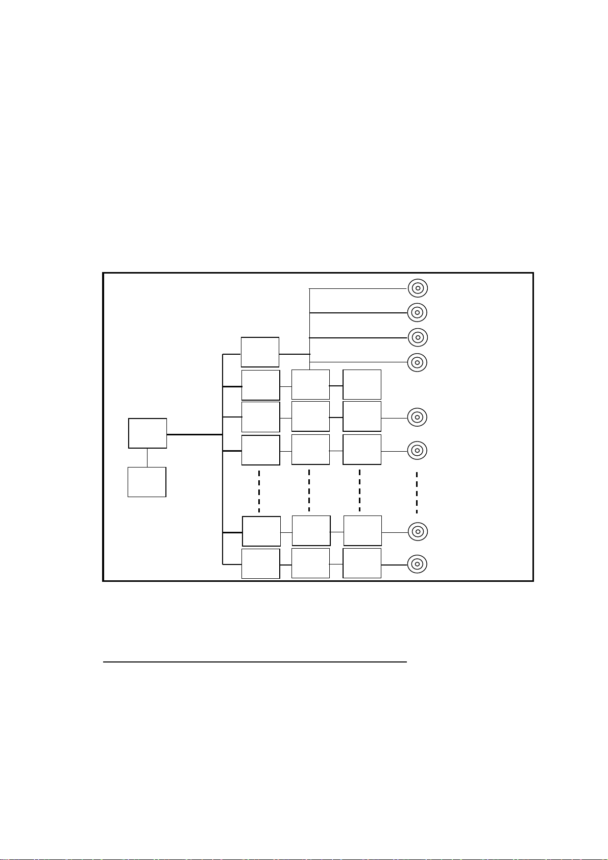
1-3.Block diagram
2-1.Confirm input signal level for count
LAN
USB
CPU
TIMER
CNT0
GATE TTL or
NIM
μs
clock
on/off
SW
RUN(TTL OUT)
START(TTL IN)
STOP(TTL IN)
GATE(TTL IN)
PULSE IN(CH7)
PULSE IN(CH6)
PULSE IN(CH1)
PULSE IN(CH0)
GATE
GATE
GATE
GATE
CNT1
CNT6
CNT7
CNT = COUNTER
NIM to
ECL
NIM to
ECL
NIM to
ECL
NIM to
ECL
4/15

When connecting PC directly, it's need to use cross cable. Otherwise using HUB module, it's no need
to use cross cable.
The way of connecting PC directly is as follows.
It's need to set IP address and subnet mask to your PC.
Set IP address to 192.168.1.10, and subnet mask to 255.255.255.0, for example.
about the way of setting address to your PC, see your PC manual.
Select MS-DOS prompt and access command "ping" in MS-DOS prompt.
C:¥Windows>ping 192.168.1.55
Pinging 192.168.1.55 with 32 bytes of data:
Reply from 192.168.1.55: bytes=32 time=2ms TTL=255
Reply from 192.168.1.55: bytes=32 time=1ms TTL=255
Reply from 192.168.1.55: bytes=32 time=1ms TTL=255
Reply from 192.168.1.55: bytes=32 time=1ms TTL=255
C:¥Windows>
If replies are listed above, physical connection is correct.
If physical connection is not correct, communication replies are these.
C:¥Windows>ping 192.168.1.55
Pinging 192.168.1.55 with 32 bytes of data:
Request timed out.
Request timed out.
Request timed out.
Request timed out.
C:¥Windows>
In this case please retry the connection again after confirming the cable connection.
Once you check connection is correct, enter new IP address and new telnet port NO of NCT08-02.
(If default NO is OK, you don't have to do this operation.)
Default IP address is 192.168.1.55, and default port NO is 7777.
IP address must to be changed according to your network system.
If there is no need to change port NO, you may use NO 7777.
If you need to change port NO, the recommended port is NO. 10000 to 10999.
In Windows screen display
START → Specify the file name and run, file name is
2-2-2.Changing setting condition for net-work
5/15

telnet 192.168.1.55 9999
NO 9999 is port set number of NCT08-02.
Click OK button and screen changed to telnet mode immediately.
MAC address 00204A80F1B6 ← It depends on the type of unit.
Software version 01.5(031003)XPTE ← It depends on the type of unit.
Press Enter to go into Setup Mode
Push Return button in 3sec.
More than 3 sec, this connection is automatically cut off. Then try again from beginning.
Next display
・・・・・・
Change Setup:
0 Server configuration
1 Channel 1 configuration
3 E-mail settings
5 Expert settings
6 Security
7 Factory defaults
8 Exit without save
9 Save and exit Your choise ?
Then select 1.
Baudrate(38400)? ・・・・・ push return.
I/F Mode(4C)? ・・・・・ push return.
Flow(00)? ・・・・・ push return.
Port No(7777)? ・・・・・enter port address of telnet, then push return
(Default port NO is 7777, if you need to change this number,
recommended port number is 10000 to 10999.)
ConnectMode(C0)? ・・・・・ push return.
Remote IP Address:(000).(000).(000).(000
)
・・・・・ push return three times.
Remote Port (0)? ・・・・・ push return.
DisConnMode(00)? ・・・・・ push return.
FlushuMode (80)? ・・・・・ push return.
Pack Cntrl (20)? ・・・・・ push return.
DisConnTime(00:00)? ・・・・・automatically power down set time when in no connection.
(set data is **:++ means **minutes and ++seconds)
(default data 00:00 means 5999s = 99min 59sec
SendChar 1 (0D) ・・・・・ push return.
SendChar 2 (0A) ・・・・・ push return.
Select 9, then finished setting works
Change Setup:
6/15

0 Server configuration
1 Channel 1 configuration
3 E-mail settings
5 Expert settings
6 Security
7 Factory defaults
8 Exit without save
9 Save and exit Your choise ?
In these setting items, only IP address must be set. Other items may be no change to set.
If you enter wrong number by mistake, you'd better to retore above data.
2-2-3.Turn back PC set data
If you change setting data of PC, turn back PC data to initial condition.
Let's try connecting test by optional Windows software such as "telnet".
Example test data is "telnet 192.168.1.55 7777" in MS-DOS prompt screen.
(IP address number must to be set number preliminary. )
When in telnet operation, send data "VER?" which are expected reply data.
If reply data is like ”1.00 05-07-07", then communication line is right.
"Telnet" function contains hardware and software function, when disconnect line, line must be cut off
by "telnet" software operation before hardware disconnection.
Driver software for USB (Universal Serial Bus) operation is downloaded from our web server.
By installing this software, connecting is done like a COM port connection.
Switch on a NCT08-02, connect USB cable, then there will be message box that shows "New hardware
device was found". According to PC directions, specify the folders of downloaded driver software.
When the driver software installs are done, open the "Control Panel" ( START → Control Panel),
click the "System" icon. Then property display of system appears. Select the "Device Manager".
Confirm the USB Serial Port (Com*) number in the tree between Port display.
Select the USB Serial Port (Com*), click Advanced in Port Setting display. It's possible to change
COM Port number. Click the check box Disable PNP □ , it's possible to short operation time in
connecting USB cable again.
Launch RS-232C communication software such as hyper-terminal included in your PC.
Set COM port number which is known in previous item, it's need to check communication line is available
or not. In this case It's no need to set baud rate. Send the command data such as "VER?", then get
the reply "1.00 04-09-03", there is no problem for communication
Connect the communication cable to USB port or LAN port on rear panel.
There is no need to connect both side, but there will be no problem even if connect both side.
If connected both side, latest command will be valid to the unit.
2-2-4.Connecting test
2-3.Setting USB communication
2-3-1.Preparations for setting
2-3-2.Connecting test
2-4.Connect signal cables
2-4-1.Connect communication cables
7/15

Connect count signal cable to CH0 to CH7 LEMO connector which are on front panel.
It' s possible to count maximum 8 channel signals.
2-4-3.Start signal (TTL positive logic)
TTL positive logic signal starts counting action.
The width of start signal pulse must be more than 100ns.
It's possible to check the count start status by LED lamp on front panel.
It counts from start signal "ON" to stop signal "ON".
Without this signal you can alse start counting by software commands via LAN or USB.
2-4-4.Stop signal (TTL positive logic)
TTL positive logic signal quits counting action.
The width of stop signal pulse must be more than 100ns.
It's possible to check the count stop status by LED lamp on front panel.
It counts from start signal "ON" to stop signal "ON".
Without this signal you can alse stop counting by software commands via LAN or USB.
2-4-5.Gate signal (TTL positive logic)
Gate signal is TTL positive logic signal.
When gate signal goes "L" counting action stopped during "L" period.
When gate signal goes "L" LED lamp is "OFF" during this period.
LED lamp goes "ON" during gate signal is "H" when counter starts.
When gate signal is no connection, gate signal is equal to logic "H".
Run signal goes "H" when counting action is valid. It means count start and "Gate signal" are
in "H" logic, and LED goes "ON".
It's useful to use more than two counter units. Connecting this line to "Gate signal input" of another
unit, another units go active counting action. Of course another units must be active in count mode
before Run signal go "H".
Command characters are ASCII data.
The delimiter of communication command is CR+LF in transmit and receive case.
Type of command
ENCS Enable to stop count by counter(CH7).
When count value of preset channel (CH7) reach to preset value,
count action automatically stopped.
2-4-2.Connect count signal
2-4-6.Monitor out signal(In counting, TTL positive logic
)
3.Explanation of communication commands
3-1.Communication commands
3-2.Read-out commands for counter set and the status of setting
3-2-1.Stop enable by count value
8/15

Type of command
ENTS Enable to stop count by timer.
When timer value reach to preset timer value, count action
automatically stopped.
Type of command
DSAS Disable to stop count by counter (CH7) or timer.
Counter doesn't stop automatically.
To quit counter action, it's valid to "STOP" command or "STOP" input
signal (TTL level).
Type of command
MOD? The latest counter mode is read.
Reply
R_SN_T_O R: remote mode (fixed)
SN: single mode (fixed)
T: T/timer stop mode, C/counter stop mode, N/not stop mode
(When power switch on, the last mode data is restored)
O: O/counter On, F/counter off
(When power switch on, count function is "OFF".)
3-2-5.Setting and readout of preset counter
Type of command
SCPRdddd・・・・ To set preset value dddd・・・・・ in decimal to preset counter.
Unit is Kcts.
Maximum value is 281,474,976,710 Kcts.
SCPRFdddd・・・・ To set preset value dddd・・・・・ in decimal to preset counter.
Unit is cts.
Maximum value is 281,474,976,710,655 cts.
*) The preset value is round down to multiple number of eight.
Inquiry command format
CPR? To read out preset count value.
Reply
Reply data is 8 digit decimal value.
4294967000 (If reply data is over 8 digit, the digit is as the count digit.)
Unit is Kcts.
CPRF? To read out preset count value.
Reply
Reply data is 8 digit decimal value.
4294967000 (If reply data is over 8 digit, the digit is as the count digit.)
Unit is cts.
3-2-2.Stop enable by timer value
3-2-3.Disable auto stopping by counter value or timer v
a
3-2-4.Inquiry of action mode
00654321
00654321
9/15

3-2-6.Setting and readout of preset timer
Type of command
STPRdddd・・・・ To set preset value dddd・・・・・ in decimal to timer.
Unit is ms.
Maximum timer set value is 1,099,511,627 ms.
STPRFdddd・・・・ To set preset value dddd・・・・・ in decimal to timer.
Unit is μs.
Maximum timer set value is 1,099,511,627,775 μs.
Inquiry command format
TPR? To read out preset timer value.
Reply
00123456 Reply data is 8 digit decimal value.
4294967000 (If reply data is over 8 digit, the digit is as the timer digit.)
Unit is ms.
TPRF? To read out preset count value.
Reply
00123456 Reply data is 8 digit decimal value.
4294967000 (If reply data is over 8 digit, the digit is as the timer digit.)
Unit is μs.
Type of command
STRT Enable counter start.
Type of command
STOP Enable counter stop.
Type of command
RDAL? To read all counter channels and timer
Reply
1234567890 2345678901 3456789012 ・・・・・ 0123456789
These data are 10 digit number in decimal.
The data order is CH0 CH1 CH2 ・・・・・・ CH7 timer.
If reply data is over 10 digit, the digit is as the value digit.
Unit is cts for counter and μs for timer.
Type of command
CLAL? To clear all counter channels and timer
3-3.Commands of counter operation
3-3-1.Counter start
3-3-2.Counter stop
3-4.Read-out and clear commands for counter and timer
3-4-1.Read-out and clear commands for all counter and timer
10/15

Type of command
CTR?xx To read count value of channel number xx.
CTR?xxyy To read count value from channel number xx to channel number yy.
Reply
1234567890 Reply data is 10 digit data in decimal. Unit is cts.
1234567890 2345678901 3456789012 ・・・・・ 0123456789
Reply data is 10 digit data in decimal in order. Unit is cts.
If reply data is over 10 digit, the digit is as the value digit.
Type of command
CLCTxx To clear the count value of counter channel xx(00~07).
CLCTxxyy To clear the count value from counter channel xx to channel yy.
CLPC To clear the count value of preset counter channel 07.
Type of command
TMR? To read timer value.
Reply
1234567890 Reply data is 10 digit data in decimal. Unit is μs.
If reply data is over 10 digit, the digit is as the value digit.
Type of command
CLTM To clear timer value.
3-5.Inquiry of over-flow count data
Type of command
ALM? To inquiry about data overflow timer and count data
Reply example
overXXXX-- Timer is in normal.
overXXXXTM Timer is overflow.
XXXX means overflow counter channel. XXXX is 4 digit hex data.
(Example)
over0001-- It means counter CH0 is overflow. [0000 0001]
over0009-- It means counter CH0 and CH3 are overflow. [0000 1001]
over0039-- It means counter CH0,CH3, CH4 and CH5 are overflow. [0011 1001]
over000ATM It means counter CH1,CH3 and timer are overflow. [0000 1010]
over0000-- It means no overflow. [0000 0000]
Type of command
VER? To inquiry about software version information
Reply example
1.00 07-01-05 NCT08-02
Reply is in order, version number, date and type of the unit.
3-4-2.Read-out and clear commands for all counter
3-4-3.Read-out and clear commands for timer
3-6.Inquiry of software version information
11/15

3-7.Other commands
(a) Type of command
FLG?0 FLG?1 FLG?2
Each command show the contents of unit. Details are as these.
Reply for command "FLG?0"
b7:
b6:
b5:
b4:
b3: Counter number 3 overflow
b2: Counter number 2 overflow
b1: Counter number 1 overflow
b0: Counter number 0 overflow
Reply data "04" mean "Counter number 2 overflow".
Reply for command "FLG?1"
b7:
b6:
b5:
b4:
b3:
b2: Counter number 6 overflow
b1: Counter number 5 overflow
b0: Counter number 4 overflow
Reply data "04" mean "Counter number 6 overflow".
Reply for command "FLG?2"
b7: Time up carry monitor
b6: RUN OUT
b5: COUNTER ON
b4: Timer overflow
b3: Counter number 7 overflow
b2: TTL GATE
b1: TTL STOP
b0: TTL START
Reply data "04" mean "Counter number 7 overflow".
(b) Type of command
FROM? To check flash ROM number which includes active firmware software.
Refer to details see item 4. 「Firmware Version Upgrade」
Reply example
FROM0
FROM1
(c) Type of command
FROM0 Select flash ROM number which includes active firmware software.
FROM1 Refer to details see item 4. 「Firmware Version Upgrade」
12/15

4.Firmware update
For NCT08-02 it's possible to upgrade firmware via communication tools.
Here is an overview of operation.
It's possible to use USB and LAN communication.
This is an example to install software by free soft "Tera Term" using LAN.
① Fist download the version upgrade software by Internet then unzip the file.
② Run "Tera Term" software.
In case of LAN mode, select "TCP/IP" enter IP address and port NO. of NCT08-02.
In case of USB mode, select "SERIAL" and click PORT number (COMX) which is assigned to USB port.
Operate "SETUP" to "Terminal", set "New-line" is CR+LF with Receive and Transmit usage.
Put check mark into Local echo, then select "OK".
Try put into command "VER?", then if there is reply, connection will be no problem.
③ By "Tera Term", select "file" and then click "send file".
Opening "File Selection Window", specify the file name which is already installed procedure ①.
Then it begins the download.
④ it's possible to check download program file by PC.
When receiving data, the "COUNT" LED lamp of unit NCT08-02 turns on and off slowly.
⑤ After receiving data for about 20s, the "COUNT" LED lamp goes to fast on and off mode then ROM writing
session begins. After 5s, "COUNT" LED lamp turns off then this session will be done.
⑥ Stop "Tera Term" then cut off the line TCP/IP or USB, turn off power line of NCT08-02.
Turn on power of NCT08-02 again, the firmware version will be new.
Without turning off power line, it gets start by "RESET" command.
There are two pieces of flash ROM(FROM) loaded inside, new firmware is installed to one piece
which is not used at now. After finishing writing a session, new one (written just now) is activated.
So after this session, by power off/on sequence or "RESET" command, new program will start.
It is possible to check the version of working FROM by the command "FROM?"
Reply data is like these,"FROM0", "FROM1".
It is possible to specify the version of working FROM by the command "FROM0" or "FROM1".
After specifying FROM version, turn on power action or "RESET" command will start again by specified
FROM version. It is useful to compare old and new firmware version.
If you miss the download work and program doesn't work, it's possible to recover initial version firmware
by the ROM print board inside.
This is the procedure of recover the program to initial state.
1.Cut off power line, open the left-side cover panel. Slide the dipswitch 2 "ON" side.
Dipswitch 1 keep "OFF" side.
2.Put on power line while shortening "GATE" input signal, "COUNT" LED turn on and off for about 15s.
After that "COUNT" LED turn off and session will be done.
3.Put off power line again, then slide the dipswitch 2 "OFF" side. Dipswitch 1 keep "OFF" side.
4.Put on power line again then program starts by initial version.
From now the latest file must be installed by procedure ① to ⑥.
13/15

It's possible to operate multi units synchronously.
The NCT08-02 contains 8 CH counters. You can use more than 9 channels at synchronous mode
using multi units of NCT08-02.
Here are procedures of this usage.
Connect the RUN signal(TTL OUT) of first unit to the GATE signal(TTL IN) port of second unit.
It's the same way to the third unit.
Send "DSAS" command to latter unit. The latter units don't stop counting automatically.
Send "START" command to latter unit. The latter units start counting action.
Depend on your usage, put on "GATE" signal to first unit.
Depend on your usage, preset timer stop command to first unit. ("CLTM","ENTS","STPRdddd")
Depend on your usage, preset counter stop command to first unit. ("CLPC","ENCS","SCPRdddd")
Activate count mode of first unit by the command "START".
This procedure activate more than one unit at the same timing chart.
(a) Regarding NCT08-02 when it receives data read command, it stops count and timer action for 120 ns.
This disable period is need to get latest data to latch 48 bits count data.
If you read out count data 100 times/s, total disable period is 120ns × 100 = 12μs/s.
Disable period for each reading access is always same 120ns.
Counter and timer stops simultaneously you'd better to read data by minimum command.
When in counting pulse during "GATE" signal which comes from outside, you'll notice that counting period
is shorter than read out period.
Unless read out count values in counting period there is no error of measurement.
When in timer stop mode or counter stop mode, there is no dead time to read out count values.
(b) Notes when count multiple units at simultaneous control. (See 5.Synchronous operation by multi counter units.)
When you use multiple units at simultaneous control, you have to pay attention to error of measurement.
Concerning only read out module, measuring period is stopped for 120ns.
There for there are some errors of pulse count between units, because of the times or timing of data read out.
Example) When read out 100Times/1s for one module.
The period of counting pulse is 12μs shorter. 120ns×100=12μs.
In this case error ratio of count is 12μs/1s (0.00012%).
5.Synchronous drive of multi units
6.Regulations and guidelines
7.Interfacing to external devices 5V
TTL IC
GATE INPUT
GND
LEMO
TTL IC
START, STOP
GND
LEMO
GND
TTL LEVEL
(0~3.3V OR 5V)
TTL LEVEL
(0~3.3V OR 5V)
14/15

Power NIM AC85V~132V 0.2A, DC +6V:0.4A, -6V:0.3A
Counter Input level Current Level -12mA~-36mA:"1" -4mA~+20mA:"0"
Input NIM Zin = 50Ω
Count frequency More than 500MHz
Input connector LEMO ERA00250
Channels 0~7channels (CH7 is preset counter)
Overflow digit When count value over the limit send the data "over"
Digit of count 48bit data(0~281,474,976,710,655 cts)
Timer 1channel 40bit 1~1,099,511,627,775 μs
Resolution 0.000001s (1μs)
Accuracy
Preset time 1 ~ 1,099,511,627,775 μs
Special 1channel CH7 Fixed
counter Preset count 1 ~ 281,474,976,710,655 cts
Counter single mode Count starts by start trigger or "START" command
Mode Enable to count within preset value one time
Temporarily turn into stop count by stop trigger or "STOP"
command
When disable to preset counter stop and preset timer stop
counting action continues until stop trigger or "STOP"
command
Enable to count or not for all channels and timer
Goes to count mode by open or "H" level
In count mode LED turn on "green"
In count mode signal out goes "H"
Connect this port to "Gate in TTL" of next unit.
It's possible to activate multiple units simultaneously
Count start input(by TTL rising edge), count stop input
(by TTL rising edge)
LAN, USB
Enable to upgrade firmware software by communication
NIM 1 UNIT
For the further information, feel free to ask us.
8.Performance and specifications
0.005%
Gate in TTL
LED in counting
Signal out
In counting
Control input
Number of channel
Number of channel
3739, Kandatsu-machi, Tsuchiura-city, Ibaraki 300-0013, Japan
TEL: +81-(0)29-832-3031 FAX: +81-(0)29-832-2662
E-mail : [email protected]
URL : http://www.tsujicon.jp
Communication
Version upgrade
Case
Tsuji-Electronics Co.,Ltd
CH0~CH8
COUNT IN GND
LEMO
GND
51
NIM LEVEL
NIM LEVEL
RECEIVER
ECL
COUNTER
15/15
Table of contents
Other TSUJI ELECTRONICS Cash Counter manuals


