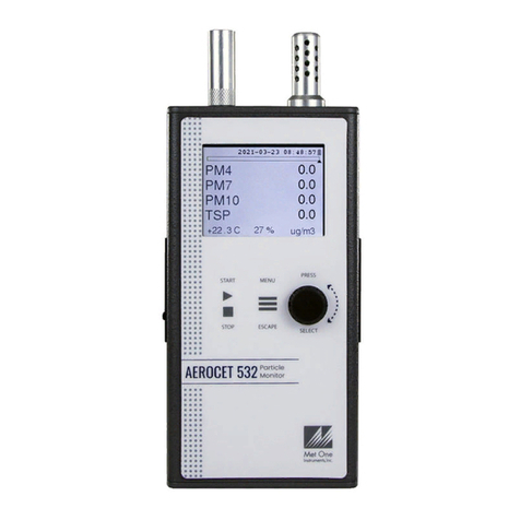
Met One Instruments AEROCET 532 User manual

Met One Instruments, Inc
Corporate Sales & Service: 1600 NW Washington Blvd. Grants Pass, OR 97526
Tel (541) 471-7111 Fax (541) 471-7116
www.metone.com serv[email protected]om
AEROCET 532
MANUAL

AEROCET 532 Manual Rev B Page 2
Copyright Notice
AEROCET 532 Manual
© Copyright 2021 Met One Instruments, Inc. All Rights Reserved Worldwide. No part of
this publication may be reproduced, transmitted, transcribed, stored in a retrieval
system, or translated into any other language in any form by any means without the
express written permission of Met One Instruments, Inc.
Technical Support
This manual is structured by customer feedback to provide the required information for
setup, operation, testing, maintaining, and troubleshooting your AEROCET 532. Should
you still require support after consulting your printed documentation, we encourage you
to contact one of our expert Technical Service representatives during normal business
hours of 7:00 a.m. to 4:00 p.m. Pacific Time, Monday through Friday. In addition,
technical information and service bulletins are often posted on our website. Please
contact us and obtain a Return Authorization (RA) number before sending any
equipment back to the factory. This allows us to track and schedule service work and to
expedite customer service. Please have your instrument serial number available when
contacting the manufacturer.
Contact
Information:
Tel: + 541 471 7111
Fax: + 541 471 7115
Web: www.metone.com
Email: service@metone.com
Address:
Met One Instruments, Inc.
1600 NW Washington Blvd
Grants Pass, Oregon 97526
U.S.A.
NOTICE
CAUTION—Use of controls or adjustments or performance of
procedures other than those specified herein may result in
hazardous radiation exposure.
WARNING—This product, when properly installed and operated, is
considered a Class I laser product. Class I products are not
considered to be hazardous.
There are no user serviceable parts located inside the cover of this device.
Do not attempt to remove the cover of this product. Failure to comply with this
instruction could cause accidental exposure to laser radiation.

AEROCET 532 Manual Rev B Page 3
Table of Contents
1. Introduction........................................................................................................... 5
2. Setup...................................................................................................................... 5
2.1. Unpacking..................................................................................................................................5
2.2. Layout........................................................................................................................................7
2.3. Default Settings .........................................................................................................................8
2.4. Initial Operation .........................................................................................................................8
3. User Interface ........................................................................................................ 8
4. Operation............................................................................................................... 9
4.1. About the Measurement ............................................................................................................9
4.2. Power Up...................................................................................................................................9
4.3. Operate Screen .........................................................................................................................9
4.3.1. Sampling ...........................................................................................................................11
4.3.2. Sample Status...................................................................................................................11
4.3.3. Sample History..................................................................................................................11
4.4. Sample Related Functions ......................................................................................................12
4.4.1. Starting/Stopping...............................................................................................................12
4.4.2. Measurement Type...........................................................................................................12
4.4.3. Sample Mode....................................................................................................................12
4.4.4. Count Mode.......................................................................................................................12
4.4.5. Sample Time.....................................................................................................................12
4.4.6. Hold Time..........................................................................................................................12
4.4.7. Sample Timing ..................................................................................................................12
5. Menu Selections.................................................................................................. 13
5.1. Edit Menu Items.......................................................................................................................13
5.2. Sample Setup Screen..............................................................................................................14
5.2.1. Location ID........................................................................................................................14
5.2.2. Measure ............................................................................................................................14
5.2.3. Mode .................................................................................................................................15
5.2.4. Count Mode.......................................................................................................................15
5.2.5. Sample Time.....................................................................................................................15
5.2.6. Hold Time..........................................................................................................................15
5.3. Toolbox Screen .......................................................................................................................16
5.3.1. Units..................................................................................................................................16
5.3.2. Memory .............................................................................................................................17
5.3.3. K-Factors...........................................................................................................................18
5.3.4. Flow...................................................................................................................................19
5.3.5. Display ..............................................................................................................................20
5.3.6. Docking Station.................................................................................................................20
5.4. Initial Setup Screen .................................................................................................................22
5.4.1. Serial.................................................................................................................................22
5.4.2. Modbus .............................................................................................................................23
5.4.3. Clock .................................................................................................................................24
AEROCET 532 Manual Rev B Page 4
5.4.4. Locations...........................................................................................................................24

5.5. About Screen...........................................................................................................................25
6. Charging the Battery........................................................................................... 25
7. Serial Communications ...................................................................................... 26
7.1. Commands ..............................................................................................................................26
7.2. Comma Separated Value (CSV) .............................................................................................28
7.2.1. Counts Format ..................................................................................................................28
7.2.2. Mass Format .....................................................................................................................29
7.2.3. Status................................................................................................................................29
7.3. MODBUS Communication.......................................................................................................30
7.3.1. Instantaneous Real Time Readings..................................................................................30
7.3.2. Last Data Record Readings..............................................................................................31
8. Maintenance ........................................................................................................ 32
8.1. Recommended Service Schedule...........................................................................................32
8.2. Zero Count Test.......................................................................................................................32
8.3. Flow Rate Test.........................................................................................................................32
8.4. Annual Calibration ...................................................................................................................33
8.5. Filter Change...........................................................................................................................33
8.6. Flash Upgrade.........................................................................................................................33
9. Troubleshooting.................................................................................................. 34
10. Specifications...................................................................................................... 35

AEROCET 532 Manual Rev B Page 5
1. Introduction
The AEROCET 532 is a full–featured, battery operated, handheld particle counter or
mass monitor.
In count mode, the unit will measure particle counts at eight fixed sizes (0.3 µm, 0.5 µm,
1.0 µm, 2.5 µm, 4.0 µm, 5.0 µm, 7.0 µm, and 10.0 µm).
In mass mode the unit will measure PM1, PM2.5, PM4, PM7, PM10 and TSP mass
concentration levels.
This instrument can store up 15,000 sample events including data from the ambient
temperature (AT) / relative humidity (RH) probe. Sample history events can be viewed
on the LCD display and downloaded to a computer.
An optional Docking Station complements the Aerocet 532. It charges the unit and
increases communication options with RS-485, Ethernet, and WiFi.
2. Setup
The following sections cover unpacking, layout and performing a test run to verify
operation.
2.1. Unpacking
Unpack and inspect the contents of the shipping container. Standard items (included)
are shown in
Figure 1 - Standard Equipment. Optional accessories are shown in Figure 2 –Optional
Accessories. Contact the supplier if any items are missing. Any damages incurred
during shipping are the responsibility of the carrier. If any damage to the shipment is
noticed before unpacking, a claim must be filed with the commercial carrier immediately.
You should follow any special unpacking instructions provided by the carrier as you then
carefully remove all items from the containers and inspect each component. It is
recommended to document and photograph all damaged packages and items before,
during, and after unpacking them. Contact Met One Instruments, Inc. (see the Technical
Support section at the beginning of this manual) to arrange for any replacement items
needed.
ATTENTION:
A Silicon Labs CP210x Driver for the USB connection must be installed before
connecting to the USB Type C port.
Driver download weblink: https://metone.com/usb-drivers/

AEROCET 532 Manual Rev B Page 6
Figure 1 - Standard Equipment
Flow Meter
PN 9801
Flow Meter
PN Swift 6.0
Docking Station
PN 83529
Figure 2 –Optional Accessories
AEROCET 532
PN AEROCET-532
Battery Charger
PN 390031
Power Cord
PN 400113
Carrying Case
PN 550537
Calibration Certificate
AEROCET 532-9600
ISO-Kinetic Probe
PN 83117
Zero Count Filter
PN G3111
USB Cable
PN 502116
Manual
AEROCET-532-9800
Rubber Boot
PN 83549

AEROCET 532 Manual Rev B Page 7
2.2. Layout
Figure 3 shows the layout of the AEROCET 532 and provides a description of each of
the components.
Figure 3 –AEROCET 532 Layout
Component
Description
Power Switch
Switch that turns the AEROCET 532 on or off. Slide up (towards inlet
nozzle) to turn on and slide down to turn off.
Charging Jack
Input jack for the battery charger. This connection charges the internal
battery pack and provides continuous operating power for the unit.
Keypad
2 key membrane keypad.
USB C Port
For USB serial communication.
Rotary Dial
Multifunction dial (rotate and press).
AT/RH Sensor
Integrated sensor that measures ambient temperature and relative
humidity.
Isokinetic Probe
The isokinetic probe reduces turbulence in the air sample. It attaches
over the air inlet nozzle.
Bottom Connection
For use with the optional 83529 Docking Station. This is used to charge
the unit and transfer data through the docking station.
Charging Jack
Isokinetic Probe
AT/RH Sensor
USB C Port
Power Switch
Rotary Dial
Keypad
Bottom Connection

AEROCET 532 Manual Rev B Page 8
2.3. Default Settings
The AEROCET 532 comes with the user settings configured as follows.
Parameter
Value
Sample Type
Mass (µg/m3)
Sample Mode
Continuous
Count Mode
Cumulative
Sample Time
1 Min
Sample Hold Time
0 seconds
Volume (concentration)
CF (particles / ft3)
Temperature Units
C
USB Baud Rate
115200
2.4. Initial Operation
Before operating the AEROCET 532 for the first time, it is recommended that the unit be
fully charged. Information regarding charging the battery is found in section 6 of this
manual.
Complete the following steps to verify proper operation.
1. Slide the power switch up to turn on the power.
2. Observe the Startup screen for 2 seconds then the Operate screen (Section 4.3)
3. Press START/STOP key. The AEROCET 532 will begin sampling.
4. Observe the PM levels on the display.
5. Turn the rotary dial to view other PM levels.
6. The unit is ready for use.
3. User Interface
The AEROCET 532 user interface is composed of a rotary dial, 2 button keypad, and an
LCD display. The following table describes keypad functionality. Note some keys have
more than one function.
Key
Description
•Operate Screen: Starts or stops a sample.
•Settings Menu: Return to Operate screen.
•Edit Setting: Cancel edit mode and return to Operate screen.
•Operate Screen: Display the Settings menu.
•Settings Menu: Return to previous screen.
•Edit Setting: Cancel edit mode and return the previous menu.

AEROCET 532 Manual Rev B Page 9
Press Function
•Operate Screen: Display the sample history.
•Settings Menu: Select the highlighted menu item.
•Edit Setting: Enter setting edit mode.
Dial Function
•Operate Screen: dial to scroll parameter list.
•Settings Menu: dial to move/scroll highlight to menu item.
•Edit Setting: dial to change picklist and numerical
parameters
4. Operation
The following sections cover the basic operation.
4.1. About the Measurement
The AEROCET 532 counts and sizes particles in 8 different size ranges then uses a
proprietary algorithm to convert count data to mass measurements (µg/m3). This
calculation includes a K-Factor setting that can be adjusted to compensate for local
particulate characteristics and improve measurement accuracy. The AEROCET 532
provides a separate K-Factor setting for each measurement range (PM1, PM2.5, PM4,
PM7, PM10, and TSP). These K-Factors can be modified on the K Factor screen as
discussed in section 5.3.3, with serial commands, or with Comet software.
K-Factor values should be empirically derived via comparison with a reference unit.
Refer to Section 5.3.3.
4.2. Power Up
AEROCET 532 power is controlled by a slide switch located on the left hand side of the
unit. Move the power switch to the on position (towards the top of the case) to power up
the unit.
The first screen shown on power up is the Startup screen. This screen briefly displays
the company logo before loading the Operate Screen.
4.3. Operate Screen
The Operate screen displays the count or mass measurement. It is determined by the
Measure setting. The Operate screen displays the sample status, date and time,
battery status, sample data, location, temperature, and relative humidity. Figure 4 and
Figure 5 show the Mass and Count screens. Four size channels are displayed. Rotate
the dial to display additional sizes and the location.

AEROCET 532 Manual Rev B Page 10
Figure 4 –Mass Operate Screen
Figure 5 –Count Operate Screen

AEROCET 532 Manual Rev B Page 11
4.3.1. Sampling
The Operate screen displays current sample information when the unit is sampling (real
time data). Concentration values are time dependent so these values may fluctuate
early in the sample; however, after several seconds the measurement will stabilize.
4.3.2. Sample Status
The top of the Operate screen displays the status of the AEROCET 532 while the unit is
sampling. The time remaining is shown at the top left of the screen. A status bar fills
with green as time progresses. If a hold time is entered, the status bar will fill yellow
during the hold time.
4.3.3. Sample History
Sample history (previous data) can be viewed on the Operate screen when the unit is
stopped or sampling. Pressing the knob puts the operate screen in History Mode.
History mode allows you to scroll through previously recorded samples and view the
historical data.
In history mode, use the dial action of the rotary knob to scroll through the previous
sample data records. Note the red arrows at the top indicate record scrolling mode (see
Figure 6). To see additional data for a given record, press down on the rotary dial to
enter the data scrolling mode. Using the dial action of the rotary knob will scroll the
data up and down and enable users to view the data stored on each channel. Data
scrolling mode is indicated by black arrows on the right side of the display (see Figure
7). Press down on the rotary knob again to switch back to record scrolling mode; use
the ESC button to exit history mode. A new sample can be started without exiting the
history mode by pressing the START button.
Figure 6 - History Record Scroll Screen
Figure 7 –History Data Scroll Screen

AEROCET 532 Manual Rev B Page 12
4.4. Sample Related Functions
The following sub-sections cover sample related functions.
4.4.1. Starting/Stopping
To start or stop a sample, press the START/STOP key. A sample event can be manually
started or stopped from either the Operate screen or the menu.
4.4.2. Measurement Type
The measurement type determines if the instrument reports mass (µg/m3) or particle
concentration (particles/volume). Measurement type is discussed in section 5.2.
4.4.3. Sample Mode
The sample mode controls single sample or continuous sampling. Sample modes are
discussed in section 5.2.3
4.4.4. Count Mode
The count mode determines if particle counts are displayed in Cumulative or
Differential mode. Count modes are discussed in section 5.2.4
4.4.5. Sample Time
The sample time is the length of time the unit will sample for. The sample time is user
selectable for 1, 2, 5, 10, 15, 30, or 60 minute samples.
4.4.6. Hold Time
The hold time is used when the sample mode is set to auto (continuous sample). The
hold time represents the time from the completion of the last sample to the start of the
next sample. The hold time is user settable from 0 –9999 seconds and is discussed in
section 5.2.6.
4.4.7. Sample Timing
The following figures depict the sample timing sequence for both manual and auto
sampling modes. Figure 8 shows the timing for manual sample mode. Figure 9 shows
the timing for auto sample mode.
Figure 8 –Manual Mode Sample
Figure 9 –Auto Mode Sample
Start
Time Sample Time Stop
Time
Start
Time Sample Time Hold Time Sample Time Stop
Time

AEROCET 532 Manual Rev B Page 13
5. Menu Selections
The Main Menu is accessible by pressing the MENU key on the Operate screen. The
table below and Figure 10 show the Main Menu items. Use the rotary dial to highlight
the desired menu item and then press it to enter that menu screen.
Menu Item
Description
Sample Setup
View / change location ID, Mass / count mode, single or
continuous mode, cumulative or differential count mode,
sample time and hold time.
Toolbox
View / change units, memory, K-factors, flow, and display.
Initial Setup
View / change serial settings, clock, and locations.
About
Display firmware version, serial number, service contact,
calibration date, and run time.
Figure 10 –Main Menu Screen
5.1. Edit Menu Items
To change settings, press MENU to display the Main Menu, rotate the dial to navigate to
the desired item and press the dial to display the item view/edit screen.
To edit pick list items (e.g. Sample Setup: Single or Continuous), rotate the dial
to navigate to the item. Press the dial to select the item. Rotate the dial to change the
setting. Press the dial to save the setting or ESCAPE to cancel and return to the
previous screen.

AEROCET 532 Manual Rev B Page 14
To edit alpha-numeric and numeric values (e.g. Location), rotate the dial to navigate
to the item. Press the dial to select the item. Rotate the dial to increment or decrement a
value. Press the dial to select the next character. Press the dial for all remaining
characters to save the value or ESCAPE to cancel and return to the previous screen.
5.2. Sample Setup Screen
Figure 11 shows the Sample Setup Screen. The 6 parameters are covered in the
following sections.
Figure 11 –SAMPLE SETUP Screen
5.2.1. Location ID
The Location ID is used to assign a unique name to a location or area. This
important field is included in sample data records (display and csv output). Use the dial
to scroll through a list of custom location IDs. To edit the list, see toolbox location ID in
section 5.4.4.
5.2.2. Measure
The Measure is either Mass or Counts concentration. It determines whether the
counter is operating in the mass measurement or particle counting mode.
When sampling in mass mode, the size selection represents the upper threshold of your
sample. For example, when you read the value for PM10 it contains all mass that is
size PM10 and lower. Conversely, when sampling in count mode, the size selections
represent the lower threshold of your sample. An example would be that the 1.0 µm
cumulative size contains all particulate that are 1.0 µm and larger.

AEROCET 532 Manual Rev B Page 15
Selection
Description
Mass
When MASS is selected the unit will report PM levels
PM1, PM2.5, PM4, PM7, PM10 and TSP in µg/m3.
Counts
When COUNTSis selected the unit will report fixed
particle sizes: 0.3 µm, 0.5 µm, 1.0 µm, 2.5 µm, 4.0 µm,
5.0 µm, 7.0 µm, and 10.0 µm.
5.2.3. Mode
The sample Mode controls single sample or continuous sampling as illustrated below.
Selection
Description
Single
The Single setting configures the unit for a single
sample.
Continuous
The Continuous setting configures the unit for
continuous sampling.
5.2.4. Count Mode
The count mode determines if particle counts are displayed in Cumulative or
Differential mode. Cumulative mode displays the particles as all sizes greater
than the selected size. Differential mode displays the counts as all particles
between the selected size and the next larger size channel. This setting is only valid for
count measurement type and will not appear on the Sample Setup screen if Mass
measure is selected.
5.2.5. Sample Time
The Sample Time is the length of time the unit will sample for. In Single mode the
unit will stop sampling after this period and in Continuous mode the unit will continue
to sample at the sample time interval. The sample time is user selectable from 1
minute, 2 minutes, 5 minutes, 10 minutes, 15 minutes, 30 minutes, or 60 minutes.
5.2.6. Hold Time
The Hold Time is the time between samples when sampling in Continuous mode.
The Hold Time is user settable from 0 –9999 seconds. The pump will remain on
during the hold period if the HOLD time is 60 seconds or less. The pump will stop after
each sample, and start a few seconds before the next sample, if the Hold time is
greater than 60 seconds. Hold times greater than 60 seconds will increase pump life,
as well as increase operating time because of lower battery usage. This setting will not
appear on the Sample Setup screen if Single mode is selected.

AEROCET 532 Manual Rev B Page 16
5.3. Toolbox Screen
Figure 12 shows the Toolbox screen.
Figure 12 –Toolbox Screen
5.3.1. Units
The Units setting allows the volume and temperature units to be selected.
Volume: The AEROCET 532 supports total counts per timed sample (TC), particles
per liter (/L), particles per cubic foot (CF), and particles per cubic meter (M3). Particle
count information updates while the unit is sampling. Concentration values (/L, CF, M3)
are time dependent so these values may fluctuate early in the sample; however, after
several seconds the measurement will stabilize.
The volume unit represents Count measure only. Mass measure volume is always
displayed in μg/m3.
AT: The AEROCET 532 displays ambient temperature (AT) in Celsius (C) or
Fahrenheit (F).
Figure 13 - Units Setup Screen

AEROCET 532 Manual Rev B Page 17
5.3.2. Memory
The AEROCET 532 can store up to 15,000 sample records in its memory. For
instructions on viewing stored data, see section 4.3.3. Because this memory is circular,
once all 15,000 records are full, any new samples taken will overwrite the oldest stored
sample data.
The Memory screen provides indication of the available memory capacity and a means
to completely erase all data currently saved in memory. The Free field shows the
percentage of space available for data storage. When 0% is displayed, the memory is
full and the oldest data will be overwritten by new data.
Press down on the rotary dial to activate the CLEAR command and erase the unit’s
memory. A confirmation screen will appear. Select the CLEAR option on the
confirmation screen to continue with erasing the data and then returning to the memory
screen. Selecting CANCEL on the confirmation screen will return to the Memory screen
without erasing the data.
Figure 14 - Memory Screens

AEROCET 532 Manual Rev B Page 18
5.3.3. K-Factors
The K-Factor for each PM mass fraction can be set in the K-Factor screen. A K-
Factor is a multiplier that is related to the specific gravity of the air being measured. It
improves the accuracy of the mass measurement when derived from a reference or
gravimetric device, because not all air is created equal. The accuracy of the mass
output can be affected by variations in size, color, shape, and index of refraction of the
sampled particles.
The individual user k-factors for each mass channel can be set from 0.1 to 20.0.
Figure 15 - K-Factor Screen
The AEROCET 532 calibration is performed using ideal polystyrene latex (PSL)
spheres, which provide a powerful tool for assessing the sensitivity, accuracy,
resolution, and false count level. The particle detector is compared to a reference mono-
dispersed (single size) suspension of PSL spheres in clean filtered air for both
calibration and certification of performance specifications. This calibration technique
provides a standard traceable reference and a measure of how well the unit maintains
its reproducibility.
Calculate the K-Factor for each particulate size fraction as the reference concentration
divided by the AEROCET 532 light scatter concentration over the same time period. For
example, if the reference total concentration was 51 μg/m3and the AEROCET total
concentration was 38 μg/m3, then the K-Factor would be 51 divided by 38 or 1.34.
The K-Factor is only valid at the same site and for the same particulate type. If the local
particulate source changes, the K-Factor may no longer be valid.

AEROCET 532 Manual Rev B Page 19
5.3.4. Flow
The Flow screen is where a flow calibration is performed. When this screen is
selected, a warning will appear to use an external flow meter to adjust the AEROCET
532 flow to 2.83 LPM. Select OK to proceed or CANCEL to exit.
The pump will start automatically when you enter the Flow screen and stop when you
leave the screen. Use the following procedure to adjust the flow rate when a periodic
flow rate check (Section 8.3) indicates a flow rate error greater than ±5%.
1. Remove the isokinetic inlet.
2. Connect a reference flow meter to the inlet fitting on the top of the unit and allow
the flow to stabilize.
3. Twist the dial clockwise to increase the flow rate and turn the dial
counterclockwise to decrease the flow rate until the measured flow rate is 2.83
LPM (0.1 CFM) ±5%.
4. Press the dial to save the calibration. Press ESCAPE to cancel without saving.
Figure 16 - Flow Screen
The progress bar shows the pump pulse width modulation (PWM) as a percentage. A
green progress bar means the PWM is in a good place. An orange progress bar
indicates the filter is getting close to needing to be replaced. A red progress bar
indicates the filter needs to be replaced.
Figure 17 - Flow Screen Progress Bar Color Changes

AEROCET 532 Manual Rev B Page 20
5.3.5. Display
The Display screen allows the user to change the backlight brightness from 10-100%
and select the display timeout to dim the screen for none, 1, 5, or 10 minutes.
Figure 18 - Display Setup Screen
5.3.6. Docking Station
The Docking Station screen is a troubleshooting feature that determines the unit
WiFi credentials if it was set up as a DHCP connection instead of a static connection
and the IP address changes. The 83529 Docking Station quick setup manual explains
how to connect the unit to the optional docking station. Select WiFi Discovery to begin
the procedure.
Figure 19 - Docking Station Screen
Other manuals for AEROCET 532
1
Table of contents
Other Met One Instruments Cash Counter manuals

Met One Instruments
Met One Instruments AEROCET 831 User manual

Met One Instruments
Met One Instruments BT-620 User manual

Met One Instruments
Met One Instruments GT-324 User manual

Met One Instruments
Met One Instruments GT-526S User manual

Met One Instruments
Met One Instruments GT-321 User manual

Met One Instruments
Met One Instruments GT-521S User manual

Met One Instruments
Met One Instruments AEROCET 532 User manual

Met One Instruments
Met One Instruments BT-610 User manual

Met One Instruments
Met One Instruments 804 User manual

Met One Instruments
Met One Instruments AEROCET 531S User manual