Met One Instruments AEROCET 531S User manual

AEROCET 531S-9800 Rev A.docx
Met One
Instruments, Inc
1600 Washington Blvd.
Grants Pass, Oregon 97526
Telephone 541-471-7111
Facsimile 541-471-7116
Regional Service
3206 Main St. Suite 106
Rowlett, Texas 75088
Telephone 972-412-4715
Facsimile 972-412-4716
AEROCET
531S
M
ANUAL

AEROCET 531S Manual Page 1 AEROCET 531S-9800 Rev A.docx
Copyright Notice
AEROCET 531S Manual
© Copyright 2013 Met One Instruments, Inc. All Rights Reserved Worldwide. No part of
this publication may be reproduced, transmitted, transcribed, stored in a retrieval
system, or translated into any other language in any form by any means without the
express written permission of Met One Instruments, Inc.
Technical Support
Should you require support, please consult your printed documentation to resolve your
problem. If you are still experiencing difficulty, you may contact a Technical Service
representative during normal business hours—7:30 a.m. to 4:00 p.m. Pacific Standard
Time, Monday through Friday.
Voice: (541) 471-7111
Fax: (541) 471-7116
Mail: Technical Services Department
Met One Instruments, Inc.
1600 Washington Boulevard
Grants Pass, OR 97526
NOTICE
CAUTION—Use of controls or adjustments or performance of
procedures other than those specified herein may result in
hazardous radiation exposure.
WARNING—This product, when properly installed and operated, is
considered a Class I laser product. Class I products are not
considered to be hazardous.
There are no user serviceable parts located inside the cover of this device.
Do not attempt to remove the cover of this product. Failure to comply with this
instruction could cause accidental exposure to laser radiation.

AEROCET 531S Manual Page 2 AEROCET 531S-9800 Rev A.docx
Table of Contents
1. Introduction ........................................................................................................... 4
2. Setup ...................................................................................................................... 4
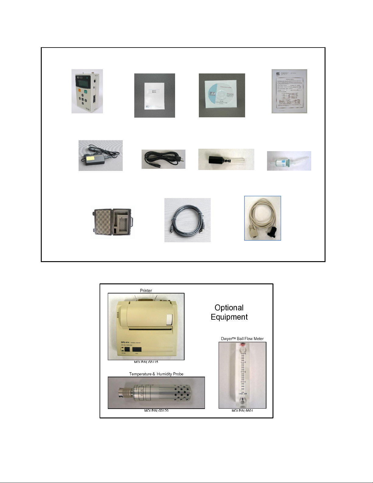
2.1. Unpacking ............................................................................................................................ 4
2.2. Layout .................................................................................................................................. 6
2.3. Default Settings .................................................................................................................... 7
2.4. Initial Operation .................................................................................................................... 7
3. User Interface ........................................................................................................ 7
4. Operation ............................................................................................................... 8
4.1. What’s New and Different ..................................................................................................... 8
4.2. About the Measurement ........................................................................................................ 8
4.3. Power Up.............................................................................................................................. 8
4.4. Operate Screen .................................................................................................................... 9
4.4.1. Sampling ...................................................................................................................... 10
4.4.2. Sample Status .............................................................................................................. 10
4.4.3. Sample History ............................................................................................................. 10
4.4.4. Warning / Error Messages ............................................................................................ 11
4.5. Sample Related Functions .................................................................................................. 11
4.5.1. Starting/Stopping .......................................................................................................... 11
4.5.2. Measurement Type ....................................................................................................... 11
4.5.3. Sample Mode ............................................................................................................... 11
4.5.4. Hold Time ..................................................................................................................... 11
4.5.5. Real-Time Serial Report ............................................................................................... 11
4.5.6. Sample Timing ............................................................................................................. 12
5. Menu Selections .................................................................................................. 12
5.1. Edit Menu Items .................................................................................................................. 12
5.2. SAMPLE SETUP Screen ...................................................................................................... 13
5.2.1. LOCATION Number....................................................................................................... 13
5.2.2. MEASURE ...................................................................................................................... 13
5.2.3. Sample MODE ............................................................................................................... 13
5.2.4. HOLD Time.................................................................................................................... 13
5.3. SETTINGS Screen .............................................................................................................. 14
5.3.1. VOLUME ........................................................................................................................ 14
5.3.2. TEMPERATURE .............................................................................................................. 14
5.4. SERIAL Screen .................................................................................................................. 15
5.4.1. REPORT ........................................................................................................................ 15
5.4.2. BAUD ............................................................................................................................ 15
5.4.3. SERIAL ........................................................................................................................ 15
5.5. RECALL DATA Screen ........................................................................................................ 16
5.6. PRINT DATA Screen .......................................................................................................... 16

AEROCET 531S Manual Page 3 AEROCET 531S-9800 Rev A.docx
5.7. MEMORY Screen .................................................................................................................. 17
5.7.1. View Available Memory ................................................................................................ 17
5.7.2. Clearing Memory .......................................................................................................... 17
5.8. SET FLOW Screen .............................................................................................................. 18
5.9. SET CLOCK Screen ............................................................................................................ 18
5.10. SET CONTRAST Screen ...................................................................................................... 19
5.11. ABOUT Screen .................................................................................................................... 19
6. Charging the Battery ........................................................................................... 19
7. Serial Communications ...................................................................................... 20
7.1. Commands ......................................................................................................................... 21
7.2. Real Time Output ................................................................................................................ 22
7.3. Comma Separated Value (CSV) ......................................................................................... 23
7.3.1. COUNTS Format ............................................................................................................ 23
7.3.2. MASS Format ................................................................................................................ 24
7.4. Printer Format ..................................................................................................................... 25
7.4.1. COUNTS Format ............................................................................................................ 25
7.4.2. MASS Format ................................................................................................................ 25
8. Maintenance ........................................................................................................ 25
8.1. Service Schedule ................................................................................................................ 25
8.2. Zero Count Test .................................................................................................................. 26
8.3. Flow Rate Test ................................................................................................................... 26
8.4. Annual Calibration .............................................................................................................. 26
8.5. Flash Upgrade .................................................................................................................... 26
9. Troubleshooting .................................................................................................. 27
10. Specifications ...................................................................................................... 28
11. Warranty / Service ............................................................................................... 29

AEROCET 531S Manual Page 4 AEROCET 531S-9800 Rev A.docx
1. Introduction
The AEROCET 531S is a full–featured, battery operated, handheld particle counter or
mass monitor. In the count mode the unit will measure particle counts at fixed sizes of
0.5u, 1.0u, 5.0u and 10.0u. In the mass mode the unit will measure PM1, PM2.5, PM4,
PM7, PM10 and TSP mass concentration levels. It also has various communication
options. This instrument can store up to 6,000 sample events including data from the
optional ambient temperature (AT) / relative humidity (RH) probe (MOI G3120). Sample
history events can be viewed on the LCD display, printed on the optional printer (MOI
G3115) and download to a computer.
2. Setup
The following sections cover unpacking, layout and performing a test run to verify
operation.
2.1. Unpacking
When unpacking the AEROCET 531S and accessories, inspect the carton for obvious
damage. If the carton is damaged notify the carrier. Unpack and inspect the contents
of the shipping container. Standard items (included) are shown in Figure 1. Optional
accessories are shown in Figure 2. Contact the supplier if any items are missing.
ATTENTION:
The included USB driver CD must be installed before connecting the AEROCET 531S
USB port to your computer. If the supplied drivers are not installed first, Windows may
install generic drivers that are not compatible with this product.
To install USB drivers:
Insert the Comet CD. The install program should run automatically and display the
screen below. If an AutoPlay pop-up window appears, select “Run AutoRun.exe”.
Finally, select “USB Drivers” to start the install process.

AEROCET 531S Manual Page 5 AEROCET 531S-9800 Rev A.docx
Figure 1 – Standard Accessories
Figure 2 – Optional Accessories
AEROCET 531S Standard Equipment
Custom Serial Cable
P/N 3228
AEROCET 531S
P/N AEROCET 531S
Battery Charger
P/N 390031
Power Cord
P/N 400133
Carrying Case
P/N 8517
Calibration Certificate
AEROCET 531S-9600
ISO-Kinetic Probe
P/N G3110
Zero Count Filter
P/N G3111
USB Cable
P/N 500787
Comet Software CD
P/N 80248
Manual
AEROCET 531S-9800

AEROCET 531S Manual Page 6 AEROCET 531S-9800 Rev A.docx
2.2. Layout
The following figure shows the layout of the AEROCET 531S and provides a description
of each of the components.
Figure 3 – AEROCET 531S Layout
Component Description
Power Switch Switch that turns the AEROCET 531S on or off. Slide up (towards inlet
nozzle) to turn on and slide down to turn off.
Charging Jack Input jack for the battery charger. This connection charges the internal
battery pack and provides continuous operating power for the unit.
USB Port For USB serial communication
Serial Port For serial communication (RS-232 or RS-485).
AT/RH Connector Mating connector for the optional external ambient temperature (AT)
and relative humidity (RH) sensor.
Inlet Nozzle Ambient air inlet nozzle. Connect isokinetic probe to reduce turbulence
in the air sample.
Charging Jack
Inlet Nozzle AT/RH Connector
USB Port
Serial Port
Power Switch

AEROCET 531S Manual Page 7 AEROCET 531S-9800 Rev A.docx
2.3. Default Settings
The AEROCET 531S comes with the user settings configured as follows.
Parameter
Value
Sample Location 1
Sample Type Mass (ug/m3)
Sample Mode Manual
Sample Hold Time 0 seconds
Volume (concentration) CF (particles / ft
3
)
Temperature Units C
Report Type None
Baud Rate 9600
Serial Mode RS-232
2.4. Initial Operation
Before operating the AEROCET 531S for the first time, it is recommended that the unit
be fully charged. Information regarding charging the battery is found in section 6 of this
manual.
Complete the following steps to verify proper operation.
1. Slide the Power key up to turn on power.
2. Observe the Startup screen for 3 seconds then the Operate screen (Section 4.4)
3. Press START/STOP key. The AEROCET 531S will sample for 1 minute and stop.
4. Observe the PM levels on the display
5. Use the up / down arrows to view other PM levels
6. The unit is ready for use
3. User Interface
The AEROCET 531S user interface is composed of a 7 button keypad and a LCD
display. The following table describes keypad functionality. Note some keys have more
than one function.
Key
Description
Starts or stops a sample.
Starts the unit printing when in the PRINT DATA screen.
Recalls the selected data when in the RECALL DATA screen.
Loads the Menu screen when not in edit mode.
Loads the Operate screen when in the Menu screen.
Cancel edit mode and return the field to the original value.
Loads the screen associated with menu item.
Begins editing of the selected item.
Stops editing a field and saves the changed value.
Scroll sizes (Operate screen)
Navigates up/down when not editing (Menu).
Modifies field when editing.
Navigates right / left
Move through history buffer (Operate screen)
MENU
ESC
ENTER
STOP
START

AEROCET 531S Manual Page 8 AEROCET 531S-9800 Rev A.docx
4. Operation
The following sections cover the basic operation.
4.1. What’s New and Different
You should be aware of key differences between the AEROCET 531S and 531.
Description 531S 531 Comments
Mass Concentration Units ug/m3 mg/m3
Mass Concentration Precision 0.1 ug/m3 0.001 mg/m3
Higher precision
Sample Time 1-minute 2-minutes Faster sample time
Hold Time Units Seconds Minutes Shorter hold times
Contrast Adjust Software Mechanical No tools required. See Section 5.10
Battery Lithium-ion NiMh Warning: See Section 6
4.2. About the Measurement
The AEROCET 531S counts and sizes particles in 8 different size ranges then uses a
proprietary algorithm to convert count data to mass measurements (µg/m3).
Fundamentally, the 531S calculates a volume for each detected particle then assigns a
standard density for the conversion.
The standard density value is adequate for most sampling environments. However,
some environments are heavily influenced by high or low density materials which can
reduce measurement accuracy. For these environments, the 531S provides a K-Factor
setting for each measurement range (PM1, PM2.5, PM4, PM7, PM10 and TSP). These
K-Factors can be modified with Comet software or with the SK serial port command.
4.3. Power Up
AEROCET 531S power is controlled by a slide switch located on the right hand side of
the unit. Move the power switch to the on position (towards the top of the case) to power
up the unit.
The first screen shown on power up is the Startup screen (Figure 4). This screen
displays the product type and company website for 2 seconds before loading the
Operate Screen.
AEROCET 531S
WWW.METONE.COM
Figure 4 – Startup Screen

AEROCET 531S Manual Page 9 AEROCET 531S-9800 Rev A.docx
4.4. Operate Screen
The Operate screen can display the count or mass measurement. It is determined by
the MEASURE setting. The Operate screen displays the date and time, sample status,
current sample data and previous sample data. Figure 5 and Figure 6 shows the Mass
and Count screens.
When sampling in mass mode, the size selection represents the upper threshold of your
sample. For example, when you read the value for PM10 it contains all mass that is
size PM10 and lower. Conversely, when sampling in count mode, the size selections
represent the lower threshold of your sample. An example would be that the 1.0u size
contains all particulate that are 1.0u and larger.
22 JAN’13 17:56
PM1 1.1 ug
PM2.5 3.3 ug
PM4 4.6 ug
PM7 5.5 ug
PM10 6.7 ug
TSP 10.6 ug
AT 21 C
RH 45 %
LOCATION 001
Figure 5 – Mass Operate Screen with AT and RH
22 JAN’13 17:56
0.5u 24,600 TC
1.0u 2,516 TC
5.0u 44 TC
10 u 21 TC
AT 21 C
RH 45 %
LOCATION 001
Figure 6 – Count Operate Screen with AT and RH
The top line of the Operate screen is reserved for the normal header (date and time) or
status/alarm messages depending upon the machine status. The top line remains
stationary while the other 3 lines scroll to display the full list. AT and RH data will
precede the location number when the AT/RH probe is attached.
Ambient temperature (AT) can be displayed in units of Celsius (C) or Fahrenheit (F).

AEROCET 531S Manual Page 10 AEROCET 531S-9800 Rev A.docx
4.4.1. Sampling
The Operate screen displays current sample information when the unit is sampling (real
time data). Concentration values (ug/m3) are time dependent so these values may
fluctuate early in the sample; however, after several seconds the measurement will
stabilize. Figure 7 shows the Operate screen while sampling.
█ 58
PM1 0.0 ug
PM2.5 0.0 ug
PM4 0.0 ug
Figure 7 – Operate Screen Sampling
4.4.2. Sample Status
The top line of the Operate screen displays the status of the AEROCET 531S while the
unit is sampling. The following table shows the various status messages:
Status Description
STARTING... AEROCET 531S is starting the sample and is waiting for the
count system to initialize.
HOLDING... AEROCET 531S is in auto mode and is waiting for the hold time
to finish.
STOPPING... AEROCET 531S is stopping the sample and is waiting for the
count system to stop.
█ █ █ █ █ █ 10 AEROCET 531S is sampling. The progress bar moves from left
to right as the sample progresses. The time remaining is
displayed to the far right.
4.4.3. Sample History
Sample history (previous data) can be viewed on the Operate screen when the unit is
stopped (not sampling). To view sample history, press the ENTER key from the Operate
screen. The unit will display the last sample event (newest record) and display “” in
the upper right corner of the display (see Figure 8) to indicate history data. Press ◄ or
► to move through sample history one record at a time (◄ displays older events, ►
displays newer events). Press the ENTER key at any time to return to the Operate
screen. Press START at any time to start a new sample.
03 DEC’12 11:23
PM1 0.0 ug
PM2.5 0.0 ug
PM4 0.0 ug
Figure 8 – History Screen

AEROCET 531S Manual Page 11 AEROCET 531S-9800 Rev A.docx
4.4.4. Warning / Error Messages
The AEROCET 531S displays warning/error messages on the top line of the Operate
screen. These messages alternate with the normal date/time header. The following
table lists the warning/error messages:
Display Message Description
LOW BATTERY! Low battery warning. Less than 15 minutes of normal operation remaining.
SENSOR ERROR! Particle sensor error.
4.5. Sample Related Functions
The following sub-sections cover sample related functions.
4.5.1. Starting/Stopping
To start or stop a sample, press the START/STOP key. A sample event can be manually
started or stopped from either the Operate screen or the menu.
4.5.2. Measurement Type
The measurement type determines if the instrument measure mass (ug/m3) or particle
concentration (particles/volume). Measurement type is discussed in section 5.2.
4.5.3. Sample Mode
The sample mode controls single sample or continuous sampling. The MANUAL setting
configures the unit for a single sample. The AUTO setting configures the unit for
continuous sampling. Sample modes are discussed in section 5.2.
4.5.4. Hold Time
The hold time is used when the sample mode is set to auto (continuous sample). The
hold time represents the time from the completion of the last sample to the start of the
next sample. The hold time is user settable from 0 – 999 seconds and is discussed in
section 5.2.
4.5.5. Real-Time Serial Report
AEROCET 531S provides real-time report out the serial port at the end of each sample.
The format of the report is controlled by the REPORT setting (Section 5.4). Section 7.2
covers the real-time output format.

AEROCET 531S Manual Page 12 AEROCET 531S-9800 Rev A.docx
4.5.6. Sample Timing
The following figures depict the sample timing sequence for both manual and auto
sampling modes. The sample time is fixed at 60 seconds. Figure 9 shows the timing for
manual sample mode. Figure 10 shows the timing for auto sample mode.
Figure 9 – Manual Mode Sample
Figure 10 – Auto Mode Sample
5. Menu Selections
The menu is accessible by pressing the MENU key on the Operate screen. The table
below shows the menu items. Press ▲ or ▼ to navigate to a menu item then press
ENTER to display a screen where you can view or change item setting(s).
Menu Item Description Press ENTER to
navigate to…
SAMPLE SETUP View / change location number, auto / manual
mode, sample type and hold time. Sample Setup screen
SETTINGS View / change volume (count units), ºC / ºF. Settings screen
SERIAL View / change report type, baud rate and
serial output mode. Serial screen
RECALL DATA Recall sample history based on time. Recall Data screen
PRINT DATA Print stored data based on a time range. Print Data screen
MEMORY View memory usage and clear memory. Memory screen
SET FLOW Adjust the sample flow rate Flow screen
SET CLOCK Set the date and time. Set Clock screen
SET CONTRAST Adjust the display contrast. Set Contrast screen
ABOUT Display firmware version and serial number. About screen
5.1. Edit Menu Items
To change settings, press MENU to display the main menu, press ▲ or ▼ to navigate to
the desired item and press ENTER to display the item view/edit screen.
To edit pick list items (e.g. SAMPLE SETUP MODE: AUTO or MANUAL), press ▲ or ▼ to
navigate to the item. Press ENTER to select the item. Press ▲ or ▼ to change the
setting. Press ENTER to save the setting or ESC to cancel and return to the main value.
Start
Time Sample Time Stop
Time
Start
Time Sample Time Hold Time Sample Time Stop
Time

AEROCET 531S Manual Page 13 AEROCET 531S-9800 Rev A.docx
To edit numeric values (e.g. LOCATION), press ▲ or ▼ to navigate to the item. Press
ENTER to select the item. Press ▲ or ▼ to increment or decrement a value. Press ◄ or
► to select the next digit. Press ENTER to save the value or ESC to cancel and return to
the main value.
5.2. SAMPLE SETUP Screen
Figure 11 shows the SAMPLE SETUP Screen. The 4 parameters are covered in the
following sections.
LOCATION: 001
MEASURE: COUNTS
MODE: MANUAL
HOLD: 000
Figure 11 – SAMPLE SETUP Screen
5.2.1. LOCATION Number
The LOCATION number is used to assign a unique number to a location or area. This
important field is included in sample data records (display, printer and csv output).
5.2.2. MEASURE
The MEASURE is either MASS or COUNTS concentration.
Selection Description
MASS When MASS is selected the unit will measure PM levels
PM1, PM2.5, PM4, PM7, PM10 and TSP in ug/m3.
COUNTS When COUNTS is selected the unit will measure fixed
particles sizes 0.5u, 1.0u, 5.0u, and 10.0u.
5.2.3. Sample MODE
The sample MODE controls single sample or continuous sampling as illustrated below.
Selection Description
MANUAL The MANUAL setting configures the unit for a single sample.
AUTO The AUTO setting configures the unit for continuous sampling.
5.2.4. HOLD Time
The HOLD time is the time between samples when sampling in AUTO mode (continuous).
The HOLD time is user settable from 0 – 999 seconds. The pump will remain on during
the hold period if the HOLD time is 60 seconds or less. The pump will stop after each
sample, and start a few seconds before the next sample, if the HOLD time is greater
than 60 seconds. HOLD times greater than 60 seconds will increase pump life.

AEROCET 531S Manual Page 14 AEROCET 531S-9800 Rev A.docx
5.3. SETTINGS Screen
Figure 12 shows the SETTINGS screen.
VOLUME: CF
TEMPERATURE: C
Figure 12 – SETTINGS Screen
5.3.1. VOLUME
The AEROCET 531S supports total counts (TC), particles per liter (/L), particles per
cubic foot (CF), and particles per cubic meter (M3). Particle count information updates
while the unit is sampling. Concentration values (/L, CF, M3) are time dependent so
these values may fluctuate early in the sample; however, after several seconds the
measurement will stabilize.
5.3.2. TEMPERATURE
The AEROCET 531S displays ambient temperature (AT) in Celsius (C) or Fahrenheit
(F).

AEROCET 531S Manual Page 15 AEROCET 531S-9800 Rev A.docx
5.4. SERIAL Screen
Figure 12 shows the SERIAL screen.
REPORT: NONE
BAUD: 38400
SERIAL: RS-232
Figure 13 – SERIAL Screen
5.4.1. REPORT
The REPORT setting determines the behavior of the AEROCET 531S serial output and
report format. The settings are NONE, CSV or PRINTER. The following table lists the
REPORT settings and describes their meanings. See section 7 for report examples.
Selection Description
NONE No report is sent to the serial port at the end of the sample
event. Reports initiated from the user interface or a serial
command will be in a CSV style report.
CSV A CVS style report is sent to the serial port at the end of the
sample event or when initiated from the user interface or a
serial command.
PRINTER A printer style report is sent to the serial port at the end of the
sample event or when initiated from the user interface or a
serial command.
5.4.2. BAUD
Use the BAUD rate selection to set the serial communications baud rate. AEROCET
531S communicates at baud rates from 300 – 38400.
5.4.3. SERIAL
The SERIAL setting controls the behavior of the AEROCET 531S serial output
hardware. The modes are RS-232 or RS-485. The following table lists the SERIAL
settings and describes their meanings.
Serial Setting
Description
RS-232 Set to RS-232 when communicating with RS-232/USB
hardware.
RS-485 Set to RS-485 when communicating with RS-485 hardware.

AEROCET 531S Manual Page 16 AEROCET 531S-9800 Rev A.docx
5.5. RECALL DATA Screen
Stored sample events can be viewed from the Operate screen but this requires
navigating one record at a time to reach a desired record. The RECALL DATA screen
provides a way to quickly navigate to a record based on time. Figure 14 shows the
RECALL DATA screen.
RECALL DATA
01 JAN’00 00:00
Figure 14 – RECALL DATA Screen
To recall data, enter the desired date/time string and select the START/STOP button.
The unit will recall the data from the date/time entered (if an exact match is found) or the
next most recent data available. The screen shown when the data is recalled is the
Operate screen. The unit will display “” on the upper right corner of the display to
indicate history data.
5.6. PRINT DATA Screen
Stored sample events can be printed through the printer port within a user selected
range. To print selected data, select PRINT DATA from the menu. Figure 15 shows the
PRINT DATA screen.
MEASURE: COUNTS
LOCATION: 001
01 JAN’00 00:00
18 AUG’06 13:23
Figure 15 – PRINT DATA Screen
Edit the location and time range to select which sample events to print. The following
table describes settings.
Setting Description
MEASURE Print MASS or COUNTS data type events.
LOCATION The location ID of the sample events to print. Setting
location to 000 prints all locations. Settable from 0 – 999.
01 JAN’00 00:00 The date/time to begin printing sample events from.
18 AUG’06 13:23 The date/time to stop print samples at.

AEROCET 531S Manual Page 17 AEROCET 531S-9800 Rev A.docx
After the print settings have been selected, the PRINTING STATUS screen is displayed.
Figure 16 shows the PRINTING STATUS screen as it would look when finished.
PRINTING STATUS
SCANNING...15
PRINTING...10
FINISHED!
Figure 16 – PRINTING STATUS Screen
Pressing the ESC button cancels the data printing and loads the menu. The format of
the print is dependent upon the SERIAL setting (Section 5.4).
5.7. MEMORY Screen
The AEROCET 531S memory is composed of a single file which contains the data from
sample events. Every time a sample is completed, the AEROCET 531S stores that
data into the memory. The AEROCET 531S memory is circular, meaning when the
memory is full, the unit will start overwriting the oldest saved samples with new
samples. AEROCET 531S provides the user the ability to view the memory usage as
well as clear the memory.
5.7.1. View Available Memory
MEMORY screen is used to view available memory or to clear the memory. The MEMORY
screen is accessed by selecting MEMORY from the menu. Figure 17 shows the MEMORY
screen.
FREE: 100%
SAMPLES: 6257
PRESS ENTER TO
CLEAR MEMORY!
Figure 17 – MEMORY Screen
FREE shows the percent of space available for data storage. When 0% is displayed,
memory is full and the oldest data will be overwritten by new data. SAMPLES shows the
number of samples which can be store in memory before the memory is full. When 0%
is displayed, memory is full and the oldest data will be overwritten by new data.
5.7.2. Clearing Memory
To clear memory, press the ENTER key while viewing the MEMORY screen. This will
delete all the sample events in memory. A warning screen will be displayed to prevent
accidental erasure.

AEROCET 531S Manual Page 18 AEROCET 531S-9800 Rev A.docx
5.8. SET FLOW Screen
The AEROCET 531S has a factory calibrated flow rate of 0.1 CFM (2.83 LPM). Use the
following procedure to adjust the flow rate when a periodic flow rate check (Section 8.3)
indicates a flow rate error greater than +/- 5%.
SET FLOW
< > TO ADJUST
ENTER TO SAVE
███████
Figure 18 – SET FLOW Screen
1. Connect a reference flow meter to the inlet fitting on the top of the unit.
2. Access the SET FLOW screen (Figure 18) by pressing MENU then select SET FLOW.
The pump will start automatically when you enter the SET FLOW screen and stop
when you leave the screen.
3. Press ◄ or ► to obtain a reading of 0.1 CFM (2.83 LPM) +/- 5% on the reference
flow meter.
4. Press ENTER to save the setting or ESC to cancel the change.
5.9. SET CLOCK Screen
To set the date and time select SET CLOCK from the menu. Figure 19 shows the SET
CLOCK screen and the following table describes the date / time formats.
SET CLOCK
DATE: 18 AUG’06
TIME: 11:25:36
Figure 19 – SET CLOCK Screen
Date / Time Formats
DATE dd MMM’yy dd – day, MMM’ – month, yy – year
TIME HH:mm:ss HH – hours, mm – minutes, ss – seconds

AEROCET 531S Manual Page 19 AEROCET 531S-9800 Rev A.docx
5.10. SET CONTRAST Screen
Press ◄ or ► to improve display quality. Press ENTER to save the setting or ESC to
cancel the change. Figure 20 shows the SET CONTRAST screen.
SET CONTRAST
< > TO ADJUST
ENTER TO SAVE
███████
Figure 20 – SET CONTRAST Screen
5.11. ABOUT Screen
Figure 21 shows the ABOUT screen. The ABOUT screen shows the firmware version and
programmable logic versions on the second line. The third line shows the
manufacturer’s serial number. Press ▲ or ▼ to toggle between the two version
numbers.
AEROCET-531S
99999-1 R9.9.9
N12345
WWW.METONE.COM
Figure 21 – ABOUT Screen
6. Charging the Battery
Caution:
The provided battery charger is designed to work safely with this device. Do
not attempt to connect any other charger or adapter to this device. Doing so
may result in equipment damage.
To charge the battery, connect the battery charger to an AC power outlet and the DC
barrel connector to the socket on the right side of the AEROCET 531S. The battery
charger is universal and will work with power line voltages of 100 to 240 volts, 50 to 60
Hz. A discharged battery pack will take approximately 2.5 hours to fully charge.
When fully charged the battery inside the AEROCET 531S will power the unit for about
10 hours of continuous sampling. Under normal operation, the battery will power the
unit for about 24 hours. For continuous operation, operate the unit with the battery
charger attached. Charge the battery before storing the AEROCET 531S. Storing a
discharged battery will degrade its performance.
Other manuals for AEROCET 531S
1
This manual suits for next models
1
Table of contents
Other Met One Instruments Cash Counter manuals

Met One Instruments
Met One Instruments AEROCET 532 User manual

Met One Instruments
Met One Instruments AEROCET 531S User manual

Met One Instruments
Met One Instruments AEROCET 831 User manual

Met One Instruments
Met One Instruments BT-610 User manual

Met One Instruments
Met One Instruments GT-321 User manual

Met One Instruments
Met One Instruments BT-620 User manual

Met One Instruments
Met One Instruments GT-521S User manual

Met One Instruments
Met One Instruments GT-526S User manual

Met One Instruments
Met One Instruments GT-324 User manual

Met One Instruments
Met One Instruments AEROCET 532 User manual