Meta Marine Beta 75 User manual
Operator’s
Maintenance
Manual
Operator’s
Maintenance
Manual
CALIFORNIA - Proposition 65 Warning: Diesel engine exhaust and some of its constituents are known to the state of
California to cause cancer, birth defects and other reproductive harm.
Heat Exchanger
& Keel Cooled
Mid Diesel Engine Range:
Beta 75, Beta 90 & Beta 105
Heat Exchanger
& Keel Cooled
Mid Diesel Engine Range:
Beta 75, Beta 90 & Beta 105

Fig 1 Typical Heat Exchanger Cooling System

1
Engine Details
IMPORTANT! Please fill in these details at moment of purchase - it really will help you!
(and it will really help us specify the correct spare parts for you).
Engine Type: Power: bhp Speed: rpm
BETA WOC NO: K
Gearbox Type:
Purchased From:
Invoice No.:
Date Commissioned:
Specification / Special Details:

2
Engine details (to be completed now) 1
Introduction 3
Engine identification 4
Initial receipt of the engine 5
Engine storage 5
Safety precautions 6
Technical specifications 7
SECTION 1: INSTALLATION GUIDELINES 8
Engine mounting 8
Engine alignment - drives, flanges, flexible couplings 9
Exhausts and mounting exhausts 12
Fuel supply and “leak off” 19
Cooling - sea water inlet system 20
Cooling - keel cooling system 20
Calorifier connections (if fitted) 21
Electrical installation 22
SECTION 2: GUIDELINES FOR OPERATION OF THE ENGINE 24
Important checks prior to initial use 24
Initial start-up and bleeding the fuel system 24
Starting and stopping 26
SECTION 3: MAINTENANCE & SERVICE GUIDELINES 29
Maintenance schedule 29
Lubrication - checking and changing oil 31
Fuel system - fuel / water separator, fuel lift pump, fuel filter 34
Cooling - fresh water system, heat exchanger 35
Sea water pump, heat exchanger 37
Tube stack and ‘wasting zinc anode’ 38
Belt tensioning adjustment 39
Air filter inspection / replacement 40
Electrical maintenance 40
Laying up - winterising 41
Troubleshooting 45
Torque settings 56
Wiring diagrams and general arrangement drawings index 57
Exhaust emission - declaration of conformity 82
Exhaust emission - durability 83
Quik reference parts list 84 & 85
Maintenance record 86
Contents

3
Beta 75, Beta 90 & Beta 105
OPERATION AND MAINTENANCE MANUAL FOR THE FOLLOWING
BETA MARINE ENGINES BASED ON KUBOTA
WELCOME TO BETA MARINE
Thank you for purchasing a Beta Marine Engine. We have made this manual to provide
you with important information and recommendations to ensure trouble free and
economical operation of the engine.
As manufacturers we have obviously written this “Operators Maintenance Manual”
from our ‘involved technical viewpoint’ assuming a certain amount of understanding of
marine engineering. We wish to help you, so if you do not fully understand any phrase
or terminology or require any explanations please contact Beta Marine Limited or its
distributors and we will be pleased to provide further advice or technical assistance.
All information and recommendations given in this publication are based on the latest
information available at the time of publication, and are subject to alteration at any time.
The information given is subject to the company’s current conditions of Tender and Sale,
is for the assistance of users, and is based upon results obtained from tests carried out
at the place of manufacture and in vessels used for development purposes. We do not
guarantee the same results will be obtained elsewhere under different conditions.

4
ENGINE IDENTIFICATION
{
A full inspection of the engine must be made immediately on delivery to confirm that there is no damage. If there
is any damage then write this clearly on the delivery note and inform your dealer or Beta Marine within 24 hours. A
photograph would always help.
INITIAL RECEIPT OF THE ENGINE
{
The engine must be stored in a dry, frost free area and this is best done in its packing case. If storage is to be more
than six months then the engine must be inhibited (contact your dealer or Beta Marine). Failure to inhibit the engine
may result in the formation of rust in the injection system and the engine bores, this could invalidate the warranty.
ENGINE STORAGE
{
1Beta Marine WOC Number
The engine serial number is shown on the rocker cover
label. It is also stamped into the crank case to the left
of the fuel injection pump, behind the fuel filter, on the
starboard side of the engine.
BETA 75, BETA 90 & BETA 105
{
3Engine Serial Number
IMPORTANT! - We are asking you to always provide the WOC (Works Order Card
number and or the engine serial number in all communications concerning your engine
2

5
Safety Precautions!
A Keep the engine, gearbox and surrounding area
clean, including the area immediately below the
engine.
B Drives - Power Take Off Areas
i) Gearbox Output Flange
The purpose of a marine diesel propulsion engine is to
provide motive power to propel a vessel. Accordingly
the gearbox output shaft rotates at between 280 and
2400 rev/min. This flange is designed to be coupled
to a propeller shaft by the installer and steps must be
taken to ensure adequate guarding.
ii) Forward End Drive
Engines are supplied with unguarded belt drives to
power the fresh water pump and battery charging
alternator. The installer must ensure that it is not
possible for injury to occur by allowing access to this
area of the engine. The three pulleys run at high speed
and can cause injury if personnel or clothing come in
contact with the belts or pulleys, when the engine is
running.
iii) Power Take Off Shaft (Engine Mounted Option)
Shaft extensions are available as an option and rotate
at between 850 and 3600 rev/min. If contact is made
with this shaft when the engine is running, injury can
occur.
C Exhaust Outlet
Diesel marine propulsion engines emit exhaust gases
at very high temperatures - around 400 - 500°C.
Engines are supplied with either wet exhaust outlet
(water injection bend) or dry outlet (dry exhaust
stub) - see option list. At the outlet next to the heat
exchanger/header tank, the exhaust outlet can become
very hot and if touched, can injure. This must be
lagged or avoided by ensuring adequate guarding. It
is the responsibility of the installer to lag the exhaust
system if a dry system is used. Exhaust gases are
harmful if ingested, the installer must therefore ensure
that exhaust pipes are led overboard and that leakage
in the vessel does not occur.
D Fuel
i) Fuel Lines
Diesel engines are equipped with high pressure fuel
injection pumps, if leakages occur, or if pipes fracture,
fuel at a high pressure can harm personnel. Skin must
be thoroughly cleaned in the event of contact with
diesel fuel.
ii) Fuel Supply Connections
Engines are supplied with 8mm compression fittings.
The installer must ensure that when connections are
made, they are clean and free of leaks.
E Oil
The Beta propulsion unit is supplied with 2 dipsticks,
one for the engine and one for the gearbox. Ensure
dipsticks are returned and secure after checking, if
not oil leaks can cause infection when touched. All oil
must be removed from the skin to prevent infection.
F Scalding
An engine running under load will have a closed
circuit fresh water temperature of 85° to 95°C. The
pressure cap on the top of the heat exchanger must
not be removed when the engine is running. It can
only be removed when the engine is stopped and has
cooled down.
G
Transportation / Lifting
Engines are supplied on transportable pallets. Lifting
eyes on engines are used for lifting engine and gearbox
assembly only, not the pallet and associated kit.
GENERAL DECLARATION
This machinery is not intended to be put into service until
it has been incorporated into or with other machinery. It
is the responsibility of the purchaser / installer / owner, to
ensure that the machinery is properly guarded and that all
necessary health and safety requirements, in accordance
with the laws of the relevant country, are met before it is
put into service.
Signed:
J A Growcoot, C.E.O, Beta Marine Limited.
NOTE: Recreational Craft
Where applicable, the purchaser / installer / owner and
operator must be responsible for making sure that the
Recreational Craft Directive 94/25/EC is complied with.

6
Technical Specifications
Maximum Angle of Installation: 15° flywheel up or
flywheel down when static; and up to 25° when heeling.
Rotation: Anti-clockwise on flywheel, clockwise on
gearbox output flange - for use with right hand propeller
in ahead, with mechanical gearboxes. Hydraulic
gearboxes can be left or right handed.
Fuel: Diesel fuel must conform to EN590 or ASTM D975.
Engine Lubrication: Engine oil must meet API
Classification CF (CD or CE have been superseded by CF).
Gearbox Lubrication: See gearbox operator’s manual for
the gearbox oil type and capacity.
Oil Pressure: Minimum (tickover) 0.5 bar.
Power Outputs: These comply with EN ISO 8665
propeller-shaft power.
1. Declared powers are measured at the gearbox output
flange (as coupled to the propeller shaft) as per EN
ISO 8665, developed from our standard engine
specification, including gearbox and accessories
as detailed in our current price lists. Additional
accessories or alternative gearboxes may affect the
declared powers. Declared power outputs are subject
to the stated tolerance band.
2. Operation at parameters outside the test parameters
may affect the outputs / powers.
Standard Engines Beta 75 Beta 90 Beta 105
Cylinder 4 4 4
Bore (mm) 98 100 100
Stroke (mm) 120.0 120.0 120.0
Displacement (cc) 3620 3769 3769
Combustion Indirect NA Direct NA Direct & Turbo
kW 45.8 56.0 68.1
at rev/min 2,600 2,600 2,600
N m 221.0 270.8 325.0
at rev/min 1,600 1,500 1,500
Capacity of standard sump (litres) 13.2 13.2 13.2
Nett dry weight with gearbox (kg) 414 425 430
Fuel Diesel fuel oil to EN 590 or ASTM D975
Coolant 50% antifreeze : 50% water
Coolant capacity approx. (H/E litres) 10.2 10.2 10.2
Electric starting - standard 12 Volt
Starter motor output (kW) 3.0 3.0 3.0
Alternator (battery charging) standard 70 Amps
Min. recommended battery capacity 12 Volt, 180 Ah (1200 CCA Minimum)
Power Output
EN ISO 8665
Maximum Torque

7
Section 1
Keel cooled engine, overheating is sometimes caused by:
a) Not fully venting the engine cooling system of air. It is
necessary to remove all air from the cooling system -
including the “skin” tanks and (if fitted) the Calorifier
and associated piping.
b) Incorrectly sized “skin” tanks that have been sized for
‘usual’ canal use, rather than maximum engine output
that can sometimes be required on fast flowing rivers.
An additional “skin” tank may need to be fitted; please
refer to our website: Inland waterways - guidelines:
keel cooling tank sizes.
INSTALLATION RECOMMENDATIONS FOR
KEEL COOLED ENGINES
{
The installation details are basic guidelines to assist
installation, however due to the great diversity of marine
craft it is impossible to give definitive instructions.
Therefore Beta Marine can accept no responsibility for any
damage or injury incurred during the installation of a Beta
Marine Engine whilst following these guidelines.
•All engines shall be placed within an enclosure
separated from living quarters and installed so as to
minimise the risk of fires or spread of fires as well as
hazards from toxic fumes, heat, noise or vibrations in
the living quarters.
• Unless the engine is protected by a cover or its own
enclosure, exposed moving or hot parts of the engine
that could cause personal injury shall be effectively
shielded.
• Engine parts and accessories that require frequent
inspection and / or servicing must be readily
accessible.
• The insulating materials inside engine spaces shall be
non-combustible.
INSTALLATION RECOMMENDATIONS
{
The engine compartment needs air.
a) as air (oxygen) to burn the diesel fuel, and
b) as air to keep the engine cool (still hot at 100°C)
by ventilation.
It is important that the engine compartment has adequate
ventilation, and this is your responsibility. If there is no
ventilation the engine can overheat and damage can be
caused. As a general statement an engine will produce
radiated heat - approximately equal to 1/3of the engine
output power. Also the larger battery charging alternators
create lots of heat. (A symptom of overheating problems
is often black belt dust). If you have any doubts about
the temperature of your engine compartment please
check with a thermometer on a hot day, the maximum
temperature in the engine compartment should be less
than 70°C - the cooler the better!
Engine compartment ventilation is normally best with two
holes; an inlet allowing colder air to enter below to the
alternator and drive belts and a second outlet (about the
same size) for the hot air to rise and ventilate out from the
top of the engine compartment. Adequate ventilation must
be included with all installations. Installations require a
good quality reliable electric ventilation fan wired into the
ignition switch to remove the hot air. The required air flow
volumes in m3/min = 0.05 x engine power in hp.
VENTILATION
{
10hp 20hp 30hp 40hp 50hp 75hp 100hp 150hp
Combustion 14 cm228 cm243 cm257 cm271 cm2106 cm2142 cm2213 cm2
Ventilation 13 cm225 cm237 cm250 cm262 cm292 cm2123 cm2185 cm2
Inlet / Outlet dia. 6 cm 9 cm 11 cm 12 cm 13 cm 16 cm 19 cm 22 cm
Typical ventilation sizes

8
Beta Marine propulsion engines can be installed at angles
up to a maximum of 15° flywheel up or flywheel down
when static, and can be run at up to 25° when heeling.
However if you are considering installing above 12° please
contact Beta Marine or alternatively consider the 7° down
angle gearbox. When our engines are installed at varying
angles of inclination the normal markings on the dipstick
should be disregarded. It is probably better to totally drain
the sump, and completely refill the engine sump with the
recommended quantity / volume of lubricating oil - noting
its position on the dipstick - and then marking the dipstick
accordingly (don’t forget to replace the oil filter). If in
doubt ask Beta Marine!
ENGINE INSTALLATION AT AN ANGLE
{
To ensure vibration free operation, the engine must be
installed and correctly aligned on substantial engine
bearers, extending as far forward and aft as possible, well
braced and securely fastened to form an integral part of
the hull.
The engine must be installed as low as possible on the
flexible mount pillar stud. This will limit vibration and
extend the life of the flexible mount. To assist with engine
replacement we offer ‘Special Engine Feet’ manufactured
to your dimensions, as an optional extra to suit your
existing engine bearers and shaft alignment / installation.
WARNING!
•Do not set the engine feet high up the flexible mount
pillar stud. This will cause excessive engine movement
and vibration. Pack steel shims under the flexible
mount and ensure that the flexible mounting is
securely bolted to the engine bearer.
•The pillar stud on the flexible mount is secured into
position by the lower locknut, do not forget to tighten
this. Also ensure that the stud is not screwed too far
through the mounting body so that it can touch the
bearer. This will cause vibration and knocking noises
which are very hard to find! If the flexible mounting is
too far offset then the loading on the flexible mounting
will cause premature failure, modifications are needed.
ENGINE MOUNTING
{
Recommended
Correct height
and positioning
Acceptable
Shim(s) required to achieve
correct height and positioning
NOT Recommended
Positioning too high on the
pillar stud - requires shims
NOT Acceptable
NOT aligned - requires
bearer modifications to correct
4Engine Mount
5Engine Mount Alignment
Shim

9
The engine mountings and the couplings must now be tightened in position and the alignment re-checked.
To obtain accurate alignment the flexible mountings must
be adjusted until alignment is attained, and the mountings
must be locked in position. The engine / gearbox unit has
to be aligned with the propeller shaft in two ways. The
traditional engine alignment method involves measuring
with either feeler gauges or a DTI (Dial Test Indicator)
mounted on a magnetic foot so that they are aligned
within 0.125mm (0.005”). (Obviously the propeller shaft
must be centered in the stern tube and running true -
through the cutless bearing; if the propeller shaft is not
correctly centered you will experience vibration).
ALIGNMENT
{
Angular Mis-alignment
Engine / gearbox
flange
Propeller
shaft
ANGULAR ALIGNMENT
6Angular Mis-alignment
Parallel Mis-alignment
Engine / gearbox
flange
Propeller
shaft
PARALLEL ALIGNMENT
7Parallel Mis-alignment

10
A flexible coupling is mounted on the gearbox output flange and is strongly recommended in almost every case. Flexible
couplings do not resolve bad alignment, they are designed to absorb torsional vibrations from the propeller (transmitted
along the propeller shaft).
We normally offer two types:
R&D with a flexible nylon disc and optional Clamp Coupling – a very good economical solution.
The excellent ‘CentaFlex’ coupling design includes lots of rubber to absorb torsional shocks and loads. The
‘CentaFlex’ coupling is complete, replacing both the R&D flexible and the R&D clamp couplings above.
FLEXIBLE OUTPUT COUPLINGS
{
10 CentaFlex AM Couplings
9R&D Clamp Couplings - Optional8R&D Flexible Couplings
11
Owners need to be aware of three major problems that
can easily occur when installing an engine in a sailing
yacht or motor boat and allowing the engine to ‘hydraulic
lock’.
•Seawater syphoning past worn impellors in the
seawater pump, flooding the exhaust system, and
back filling into the combustion chamber when the
engine is stopped.
•Seawater washing into the combustion chamber from
the exhaust system due to either a very shallow
exhaust run from the injection bend to the waterlock
silencer, or because the waterlock silencer is too
small to accept the total amount of cooling water in
the exhaust hoses, or both. This can happen when the
yacht is sailing into a big sea and a surge is set up in
exhaust system as the yacht pitches - with the engine
switched off.
•Waves forcing water up the exhaust due a poorly
designed system with no ‘gooseneck’. Small work
boats moored on exposed beaches are very vulnerable
to this as waves hit the stern before the boat can
swing into the wind on a rising tide.
It is therefore very important to ensure that the engine will
not ‘hydraulic lock’. This can be a problem with engine
installations. When water enters the combustion chamber
and ‘hydraulics’ against the rising piston, a bent con rod,
emulsified engine oil and a wrecked fuel pump can be the
result. It’s best avoided!
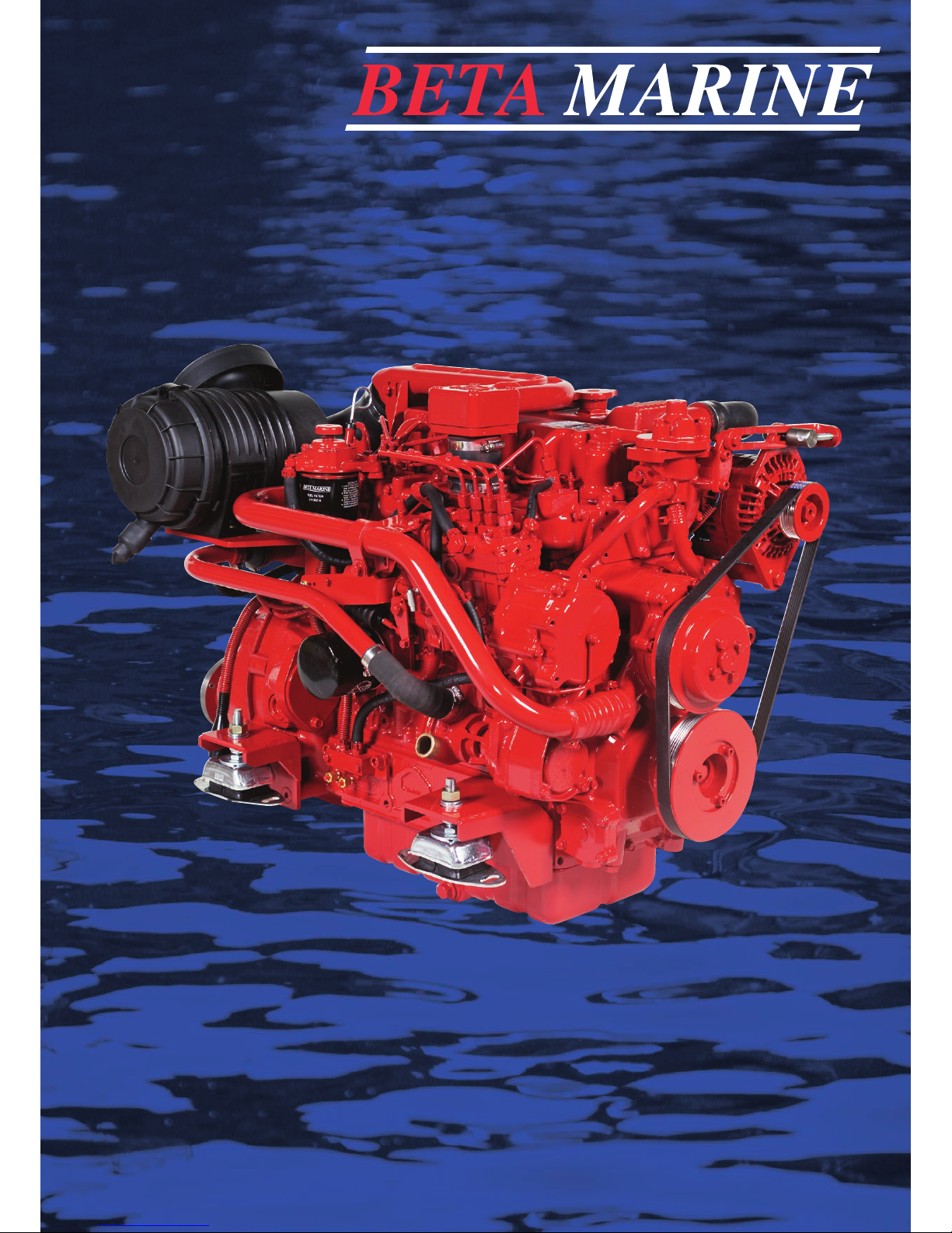
If your engine is installed below the water line, the
potential for water entering the engine is considerably
increased. The important dimension that must be
measured is from the normal ‘static’ sea level to the point
at where the cooling water is injected into the exhaust -
this should be a minimum of 25 cms. If this can not be
achieved the following options must be taken (see 11, 12
and 13).
STANDARD YACHT - WET EXHAUST INSTALLATION
{
Normal Sea
Water Level
25 cm
40 cm
Waterlock Silencer
Rope Cutter
Propeller Clearance
Gooseneck
11 Standard Exhaust System
There are two main types of exhaust system:
1) Standard yacht - wet exhaust system with a water
injection bend and waterlock silencer
2) Dry exhaust system (see page 17)
We recommend care when designing your exhaust
system. The most important aspect is to ensure that water
cannot enter the engine’s combustion chamber from the
exhaust system (this applies to both wet and dry exhaust
systems).
EXHAUST SYSTEMS
{

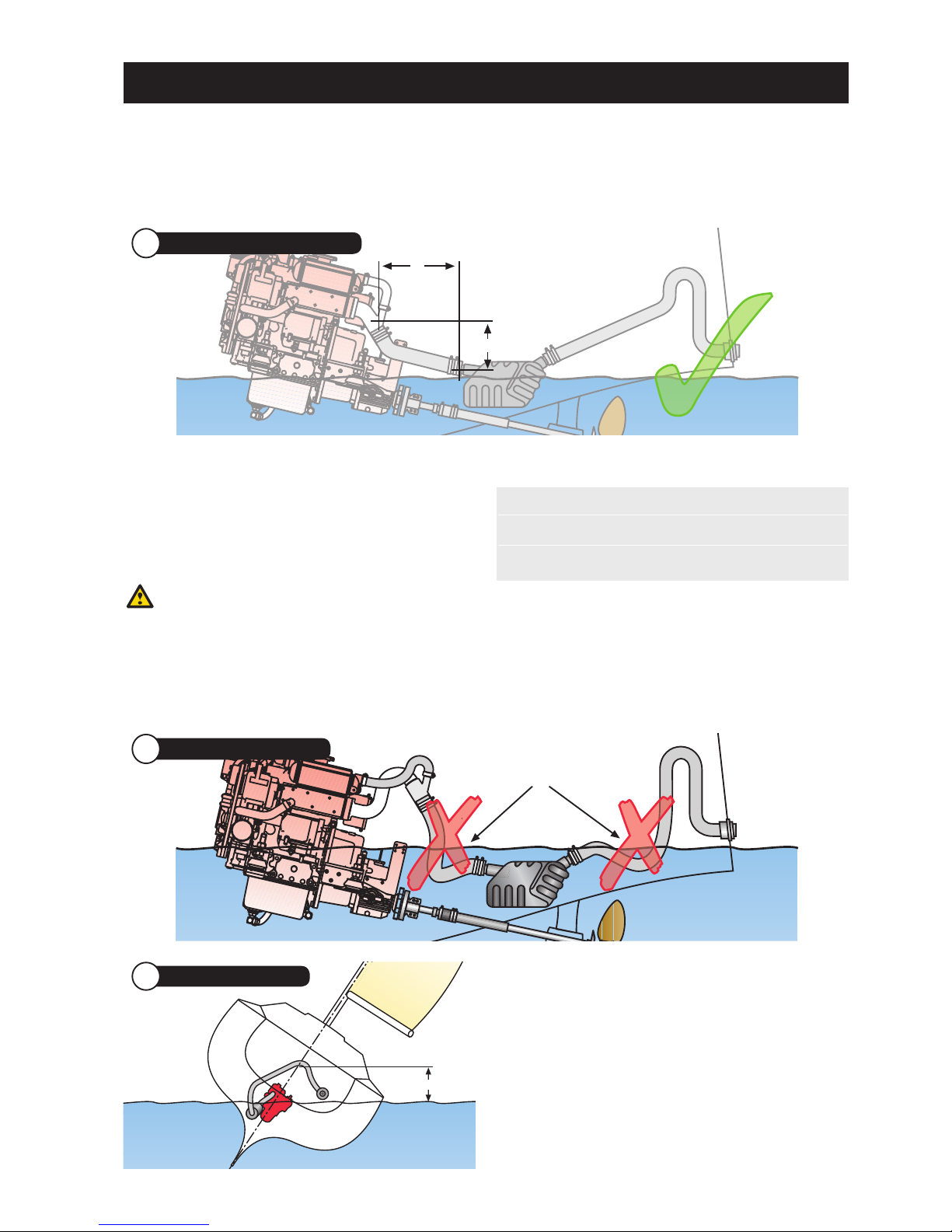
12
50 cm
13 Exhaust with Anti-syphon Valve
50 cm
In yachts, engines are mostly installed low down and
often below the water line. There are several ways to
avoid cooling water entering the engine.
Syphoning of cooling water can occur when the rubber
impellor of the sea water pump becomes worn. If our
standard injection bend is too low then we can offer a
high-rise injection bend that adds 15 cms to the height.
If this is still not enough then you have to fit an
‘antisyphon’ / vacuum valve 50 cms above the ‘loaded’
water line sea level (see 13 below).
HIGH-RISE EXHAUST
{
When the engine is installed with the standard injection
bend - and the water injection point is still less than 25
cms above the ‘static’ seawater level or is below it, then
you should either install a high rise injection bend adding
15 cms to the height or an anti-syphon valve to resolve
the problem.
Some installers will always fit an ‘Anti-Syphon’ valve in
yachts, regardless of the position of the injection bend -
just to be as safe as possible. When fitting an anti-syphon
valve to a yacht, it must be mounted as near as possible
to the centerline so that there is no possibility that the
valve goes under the water line when the yacht heels
over.
IMPORTANT!
These valves need to be checked regularly as they have
been known to block up with salt crystals over time.
EXHAUST WITH ANTI-SYPHON VALVE
{
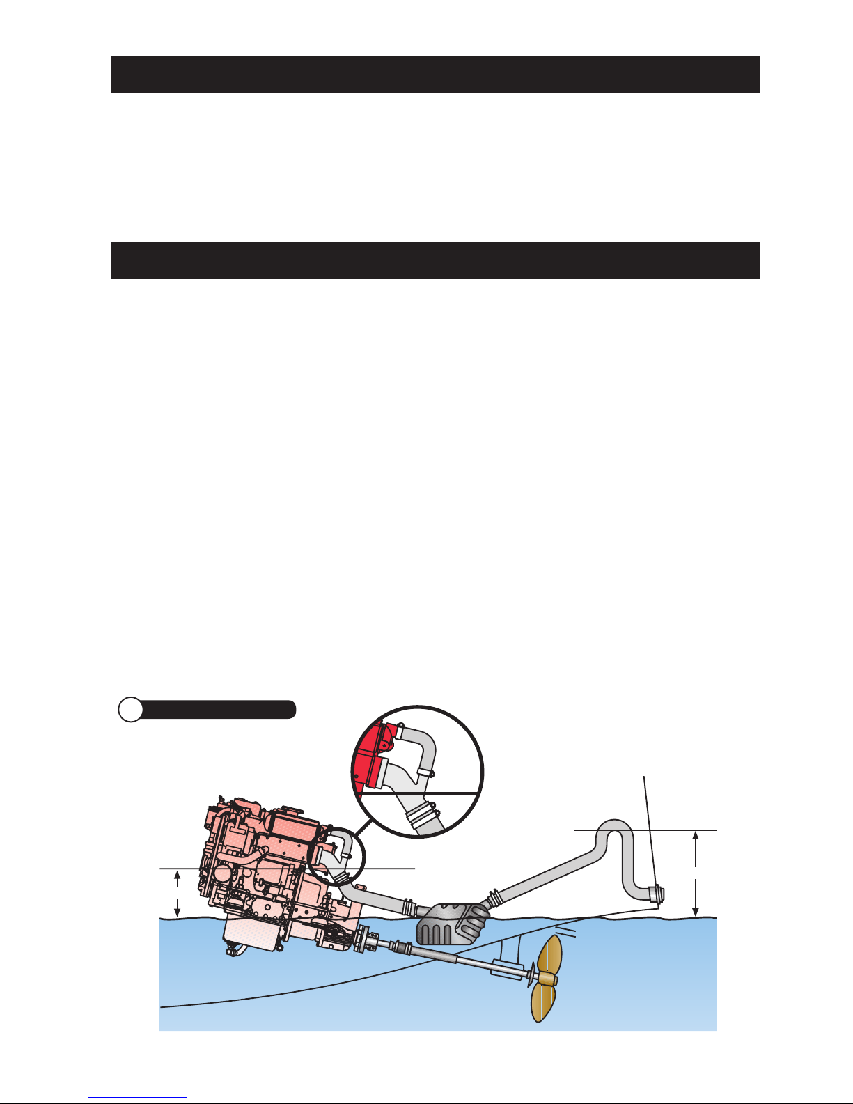
25 cm
Less then 25 cm - Not acceptable
MUST be 25 cm Minimum
12 Exhaust with High Rise
25 cm
Less then 25 cm - Not acceptable
MUST be 25 cm Minimum
Standard exhaust system for comparison only
Standard exhaust system for comparison only
13
You should always create a ‘gooseneck’ with the exhaust
hose (or purchase a propriety one) by raising the exhaust
hose 40 cms above the waterline before exiting the
transom at least 5 cms above the waterline. This will stop
any waves pushing seawater down the exhaust.
IMPORTANT!
If measurement ‘H’ cannot be met, a high rise exhaust
injection bend must be installed so that any residual water
flows / drains into the waterlock / silencer or overboard.
Position of silencer in relation to exhaust hose length:
With longer lengths of exhaust hose you may need to
support the hose to avoid a drooping hose and water
build up.
Length (L) Height (H)
30 cm 30 cm
120 cm 40 cm
WATERLOCK / SILENCER
{
Loops Holding Water
MUST be Avoided!
15 Exhaust Hose ‘Gooseneck’
H
L
14 Waterlock / Silencer Positioning
40 cm
16 Exhaust ‘Gooseneck’
You must always fit a waterlock / silencer to stop any
water in the exhaust system back filling the engine. The
water lock should always be fitted at least 30 cms away
from the injection bend and at least 30 cms below the
injection bend, being as low as reasonably possible, so
that all the water can drain down into it. The waterlock
should have sufficient capacity to hold an exhaust system
full of water - draining into it.
14
Your engine is fitted with a gear driven sea water pump
which sucks in seawater (raw water) to cool the closed
circuit system via the heat exchanger.
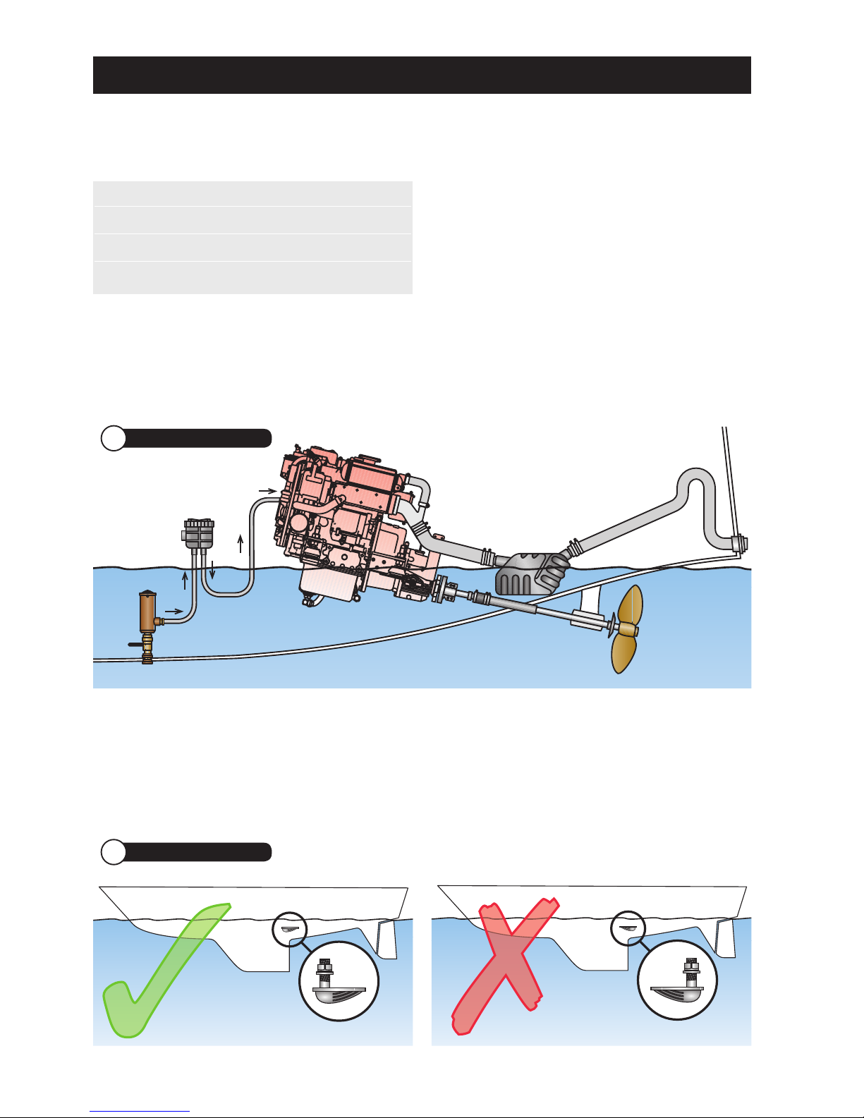
1. It is very important that the seawater inlet should have
a strainer system either ‘A’ built into the sea cock, or
‘B’ a high level system with visual inspection glass (as
shown) mounted just above the water line.
2. Good access to the inlet sea cock from inside your
boat is essential so that plastic bags or seaweed
trapped in the intake can be poked out.
3. All pipe work should have approved marine grade
stainless steel hose clips. Any loose clamps or bad
connections can cause flooding and sinking of the
vessel. It is accepted practice that two stainless steel
clips should be used at each end of raw water pipes
for security. Ensure that you use the correct grade of
hose.
Note: The maximum lift of the sea water pump is 2m
when primed.
4. A normal inlet sea cock type ‘A’ (as shown in 17
above) is recommended as this can be ‘rodded out’
to remove blockages. We do not recommend the use
of ‘Scoop’ type water pickups, because if fitted the
wrong way around the water will be forced through the
pump and into the exhaust system whilst the vessel
is sailing. This is very dangerous as the exhaust will
eventually fill and sea / raw water will back up into the
engine through the exhaust valve. Catastrophic failure
will result as soon as the engine is restarted.
SEA WATER INLET FOR HEAT EXCHANGER COOLED ENGINES
{
18 Sea Water Inlet - Scoop
Engine Seacock Inlet / Hose I.D
Beta 10 to Beta 38 19 mm / 3/4“ min.
Beta 43 to Beta 60 25 mm / 1“ min.
Beta 75 to Beta 105 28 mm / 11/4” min.
Sea Water Level
Sea Water Level
17 Sea Water Inlet / Filter
‘A’
‘B’
15
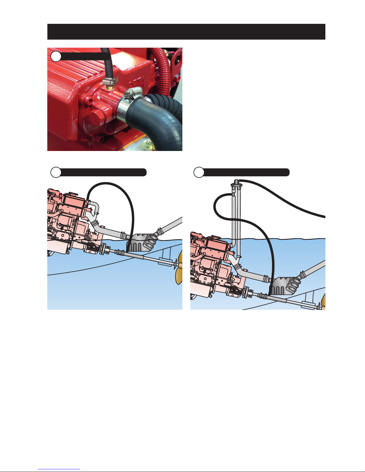
If your installation requires a water ‘bleed’ for stern gear
lubrication of the cutlass bearing it can be taken from the
engine as it leaves the heat exchanger.
19 Stern Bleed Feed
STERN GEAR LUBRICATION
{
Beta 10 to Beta 60 - can be connected to the heat
exchanger end cap using our ‘Stern Bleed kit’ and drilling
and tapping the end cap.
Beta 75 upwards - need a ‘T’ piece with an 1/8” BSP
connection fitted just after the heat exchanger as shown
in the drawing. It is important that this ‘feed’ is taken
from the engine side of an anti-syphon valve or you can
‘hydraulic’ the engine with catastrophic results.
20 Standard Exhaust with Stern Bleed 21 Stern Bleed with Anti-syphon Valve
16
EXHAUST BACK PRESSURE
{
Keep exhaust systems to a minimum length and have
gradual bends (NOT right angle elbows). Exhaust back
pressure should be as low as possible; it is increased
by long exhaust length and sharp bends. Back pressure
should be measured with the complete exhaust system
connected and the engine running at full speed. The
correct measuring point is before the injection bend (at
the manifold flange).
We can supply a Manometer kit for
testing ‘Back Pressure’.
Engine Max. Exhaust Back Pressure
Beta 10 to Beta 25 70 mm Hg
Beta 30 to Beta 60 80 mm Hg
Beta 75 to Beta 105 90 mm Hg
EXHAUST HOSE
{
Wet exhaust hose should be matched to the injection
bend diameter. An engine correctly installed in
accordance with this handbook will meet the emission
requirements of the RCD (Recreational Craft Directive).
Engine Internal Hose Diameter
Beta 10 to Beta 60 50 mm
Beta 75 & Beta 90 60 mm
Beta 105 75 mm
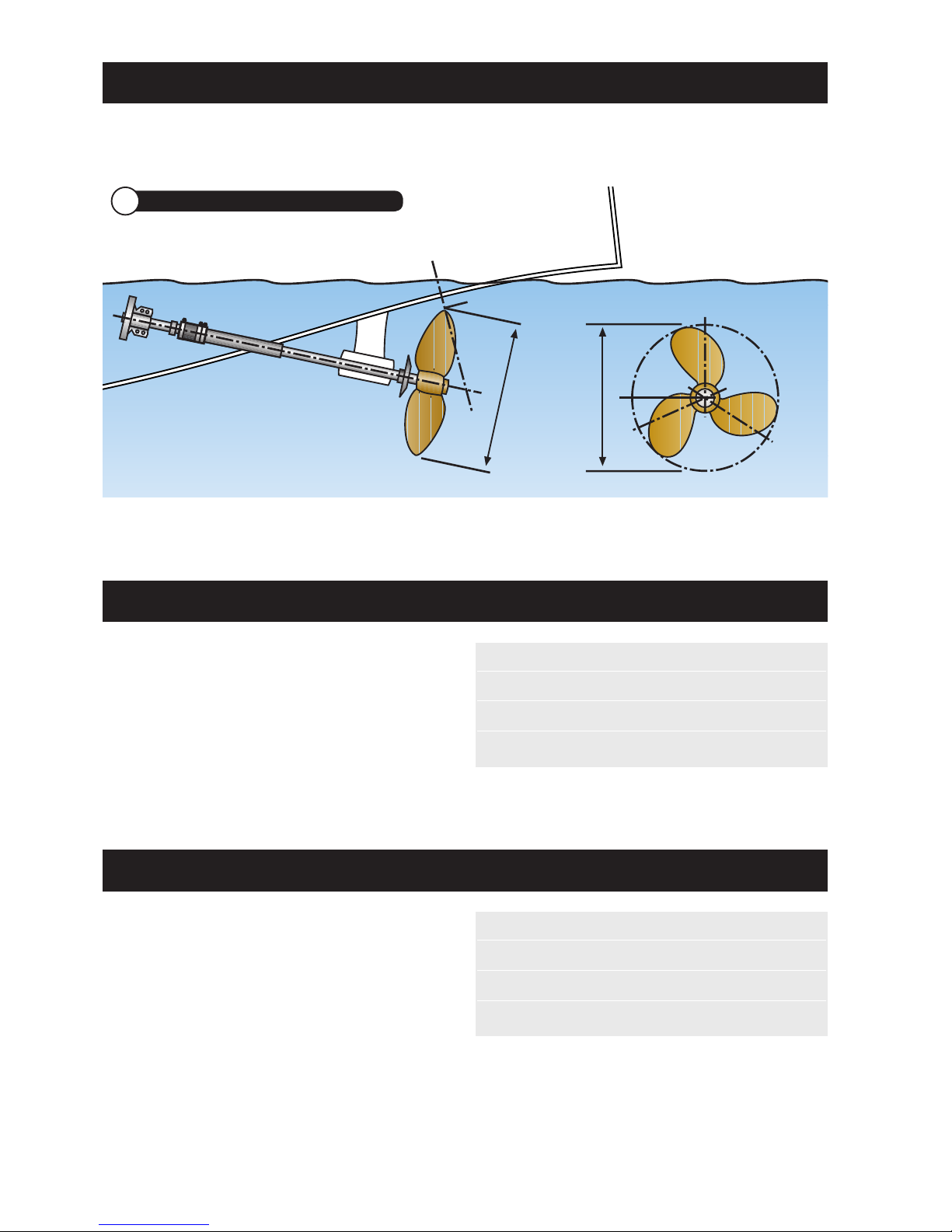
There must be a propeller clearance between the tip of
the propeller blade and the underside of the hull.
This should be a minimum of 10% of the diameter of the
propeller (some say 15%) to reduce ‘tip noise’.
PROPELLER CLEARANCE
{
10% of Prop Dia.
xx
22 Propeller Clearance

17
Flexible
Exhaust Hose
Silencer
Silencer
24 Dry Exhaust System
Flexible
Exhaust Hose
Silencer
Silencer
a) An engine correctly installed in accordance with this
handbook will meet the emission requirements of the
RCD (see back of manual).
b) Keep exhaust systems to a minimum length and
have gradual bends, refer to ‘exhaust back pressure’
bottom of page 16 for futher information.
c) The dry exhaust system installed in a canal boat
or work boat should be 1
1/2
” minimum internal
diameter.
The engine is fitted with a 1
1/2
” BSP male connector
stub as standard - Valid for exhaust systems up to
3 metres in length. A flexible exhaust bellows and
dry exhaust silencer should be used. It is up to
the installer to work out his own pipe run but care
should be taken as follows:
•Never use a flexible exhaust bellow as a bend, it will
crack, always keep them straight.
•Ensure that rain water (or any other water - say from
the side of the loch) cannot enter the exhaust port
and run back down the system, flooding the silencer
and eventually the engine (see drawings below).
•The system should be lagged if there is any danger of
the crew getting near it.
•A dry exhaust system will give off considerable heat
and suitable insulation and ventilation must be
provided.
DRY EXHAUST INSTALLATION
{
23 Dry Exhaust System
Ensure exhaust raises then falls to outlet
18
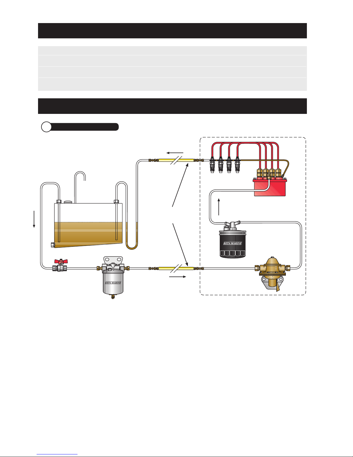
FUEL SUPPLY & LEAK OFF
{
NOTES:
1. A fuel / water separator must be installed.
2. The mechanical fuel lift pump is fitted to all engines
as standard, but if a suction head of 0.25m or more
is required, then an electric fuel lift pump must be
fitted (ask your dealer or Beta Marine).
3. It is very important that the excess fuel from the
injectors is fed back to the fuel tank and not back to
any point in the supply line. This will help prevent air
getting into the system.
4. The fuel return (leak off) pipe must loop down to
be level with the bottom of the tank before it enters
the top of the tank – see drawing. This prevents fuel
‘drain down’.
5. Fuel lines and hoses connecting the fuel tank to the
engine, must be secured, separated and protected
from any source of significant heat. The filling,
storage, venting, fuel supply arrangements and
installation must be designed and installed so as to
minimise the risk of fire. When connecting the engine
to the fuel supply and return lines, flexible fuel hoses
must be used (next to the engine) and must meet the
requirements detailed in standard ISO7840:1995/
A1:2000 and/or as required by your surveyor /
authority.
6. Any fuel leaks in the system when static are likely to
cause poor starting and erratic running and must be
corrected immediately. These leaks will allow air to be
sucked in when the engine is running.
Fuel tank
Stop tap / valve Fuel / water
separator
Fuel filter
Fuel lift pump
Fuel injection
pump
Engine (All Fuel Connections Supplied)
Flexible Fuel
Connections
to be used
Fuel injectors
Vent
25 Fuel Supply and Leak Off
ENGINE CONNECTIONS
{
Actual Connector: Required Pipe Size:
Fuel supply and leak-off = 8 mm conex with olives 8 mm OD piping for both, a flexible section is required
Seawater cooling pump = 28 mm OD Seawater pump inlet = 28 mm ID hose
Exhaust water injection bend = 60 mm OD Flexible rubber exhaust pipe of correct quality = 60 mm ID
This manual suits for next models
2
Table of contents


