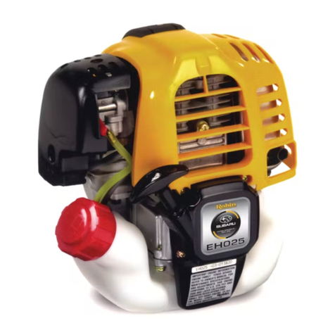
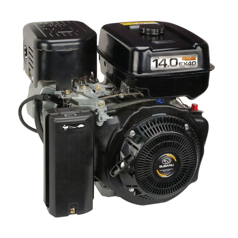
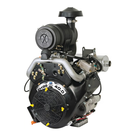
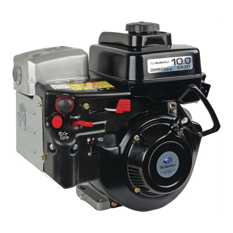
Subaru EH09-2D User manual

2121
2005.06

CONTENTS
Section Title Page
1. SPECIFICATIONS . . . . . . . . . . . . . . . . . . . . . . . . . . . . . . . . . . . . . . . . . . . . . . . . . . . . . . 1
2. DISASSEMBLY AND REASSEMBLY
2-1 DISASSEMBLY PROCEDURES . . . . . . . . . . . . . . . . . . . . . . . . . . . . . . . . . . . . . . . . . . . . . . 2
2-2 TIGHTENING TORQUE CHART . . . . . . . . . . . . . . . . . . . . . . . . . . . . . . . . . . . . . . . . . . . . . 13
2-3 REASSEMBLY PROCEDURES . . . . . . . . . . . . . . . . . . . . . . . . . . . . . . . . . . . . . . . . . . . . . 19
2-4 BREAK-IN OPERATION . . . . . . . . . . . . . . . . . . . . . . . . . . . . . . . . . . . . . . . . . . . . . . . . . . . 35
2-5 ENGINE SPEED ADJUSTMENT . . . . . . . . . . . . . . . . . . . . . . . . . . . . . . . . . . . . . . . . . . . . . 35
3. TROUBLESHOOTING . . . . . . . . . . . . . . . . . . . . . . . . . . . . . . . . . . . . . . . . . . . . . . . . . 36
4. SERVICE DATA
4-1 CLEARANCE DATA AND LIMITS . . . . . . . . . . . . . . . . . . . . . . . . . . . . . . . . . . . . . . . . . . . . 39
4-2 TORQUE SPECIFICATIONS . . . . . . . . . . . . . . . . . . . . . . . . . . . . . . . . . . . . . . . . . . . . . . . . 44
4-3 OIL GRADE CHART . . . . . . . . . . . . . . . . . . . . . . . . . . . . . . . . . . . . . . . . . . . . . . . . . . . . . . 44
The specifications and information included in this manual were in effect at the time of printing.
FUJI HEAVY INDUSTRIES LTD. reserve the right to change the specifications and to make modifications in the
course of technical progress, at anytime without notice.
No parts of this manual may be reproduced without written permission.
– 1 –
1. SPECIFICATIONS
EH09-2D
Air-Cooled, 4-Cycle, Single-Cylinder,
Horizontal P.T.O. Shaft, OHV, gasoline engine
51 x 42 (2.01 x 1.65)
86 (5.25)
8.7
1.5 (2.1) / 3600
2.1 (2.9) / 4200
4.9 (0.5) / 3600
Counter clockwise as viewed from P.T.O. shaft side
4-stroke automotive detergent oil - SAE ; #20, #30 or 10W-30
API service class ; SE or higher (SG, SH or SJ is recommended)
Splashing type
Over Head Valve type
Forced air cooling
0.3 (0.079)
Automotive unleaded gasoline
Horizontal draft, float type
Gravity type
Flywheel magneto (solid state)
NGK : BMR4A (CHAMPION : RCJ14)
Recoil starter
Centrifugal flyweight type
Semi wet type
9.9 (21.8)
249 x 299 x 380 (9.8 x 11.8 x 15.0)
MODEL
Type
Continuous Output
Maximum Output
Direction of Rotation
Lubricant
Oil Capacity
Fuel
Spark Plug
Starting System
Dry Weight
*Specifications are subject to change without notice
Dimensions (L x W x H)
Bore x Stroke
Piston Displacement
Compression Ratio
Maximum torque
Lubrication
Valve arrangement
Cooling system
Carburetor
Fuel feed
Method of ignition
Governor
Air Cleaner system
mm (in.)
ml (cu.in.)
kW (HP) / r.p.m.
kW (HP) / r.p.m.
N•m (kgf•m) / r.p.m.
kg (lb.)
mm (in.)
1.5 (0.4)Fuel Tank Capacity liter (U.S. gal)
liter (U.S. gal)

– 2 –
2. DISASSEMBLY AND REASSEMBLY
2-1 DISASSEMBLY PROCEDURES
Step Parts to remove Remarks and procedures Fasteners
1Engine oil drain (1) Remove oil drain plug and drain oil.
(2) To discharge oil quickly, remove oil gauge.
14 mm spanner
2Recoil starter Remove recoil starter from blower housing.
Be careful of pulling direction of starter rope.
M6 x 8 : 3 pcs.
10 mm box spanner
3
Blower housing Disconnect wire of stop switch first, then
remove blower housing from crankcase.
M8 x 16 : 3 pcs.
M8 x 50 : 1 pc.
12 mm box spanner
P.T.O. shaft side
OIL GAUGE
GASKET
GASKET
OIL DRAIN
PLUG
STEP 1
M4 TAPPING SCREW : 2 pcs.
CLAMP
M8 x 50 FLANGE BOLT : 1 pc.
BLOWER HOUSING
STOP SWITCH
STEP 2
STEP 3
RECOIL STARTER
M8 x 16 FLANGE BOLT : 3 pcs.
M6 x 8 FLANGE BOLT : 3 pcs.
P.T.O. shaft side

– 3 –
Step Parts to remove Remarks and procedures Fasteners
4
Fuel tank (1) Close the fuel cock.
(2)
Disconnect fuel pipe between carburetor
and fuel cock from carburetor.
(3) Remove the fuel tank from the fuel tank
bracket.
M6 x 12 : 4 pcs.
10 mm box spanner
5
Fuel tank bracket
Fuel tank bracket 2
(1) Remove the fuel tank bracket from the
cylinder head and fuel tank bracket 2.
(2) Remove the fuel tank bracket 2.
M6 flange nut : 4 pcs.
M6 x 12 : 2 pcs.
M8 flange nut : 1 pc.
M8 washer : 1 pc.
10·12 mm spanner·box wrench
AA
WASHER : 1 pc.
FUEL PIPE : 1 pc.
CLAMP : 2 pcs.
P.T.O. shaft side
M6 x 12 FLANGE BOLT : 4 pcs.
M6 x 12
FLANGE BOLT : 2 pcs.
M8 FLANGE NUT : 1 pc.
M6 FLANGE NUT : 4 pcs.
FUEL TANK
FUEL TANK BRACKET 2
FUEL TANK BRACKET
STEP 5
STEP 4

– 4 –
A
A
MUFFLER
M6 x 16 BOLT AND WASHER AY : 2 pcs.
M8 x 16 BOLT AND WASHER AY : 2 pcs.
Do not touch
the flange bolts.
M8 FLANGE NUT : 1 pc.
CYLINDER BAFFLE
STEP 7
STEP 7
GASKET
(MUFFLER)
P.T.O. shaft side
M6 x 8 FLANGE BOLT : 1 pc.
RETAINER
CLEANER COVER
BREATHER PIPE
M6 FLANGE NUT : 2 PCS.
CLEANER CASE
GASKET
ELEMENT
STEP 6
P.T.O. shaft side
Step Parts to remove Remarks and procedures Fasteners
7
Muffler and
cylinder baffle
Remove spark plug cap first from
spark plug, muffler and cylinder baffle.
Be careful not to lose muffler gasket.
M8 bolt and washer : 2 pcs.
M6 x 16 : 2 pcs.
M8 flange nut : 1 pc.
M6 x 8 : 1 pc.
10·12 mm spanner·box wrench
6
Air cleaner (1) Detach cleaner cover, and take out
element and retainer.
(2) Remove breather pipe from cleaner
case and breather cover.
(3) Remove cleaner case.
Be careful not to lose air cleaner gasket.
M6 flange nut : 2 pcs.
10 mm box wrench

– 5 –
Step Parts to remove Remarks and procedures Fasteners
8
Governor lever (1)
Loosen the bolt and remove governor lever.
(2)
Unhook governor spring from governor lever.
Mark the hole on which the governor
spring is hooked.
M6 x 25 : 1 pc.
10 mm box spanner
9
Carburetor (1) Disconnect choke knob from carburetor
choke lever, and remove choke bracket.
(Only for cyclone air cleaner)
(2) Remove carburetor carefully unhooking
governor rod and rod spring from
governor lever.
10
Speed control lever and
base plate
M6 x 8 : 2 pcs.
M6 x 14 : 1 pc.
10 mm box spanner
For cyclone air cleaner
GROMMET
M6 x 8 FLANGE BOLT : 2 pcs.
M6 x 14 FLANGE BOLT : 1 pc.
M6 x 25 BOLT AND
WASHER AY : 1 pc.
GOVERNOR ROD
SPEED CONTROL LEVER AY
GOVERNOR SPRING
ROD SPRING
STEP 9
STEP 8
STEP 10
FRICTION WASHER
WASHER
STOP PLATE
CHOKE KNOB
CHOKE BRACKET
GASKET (INSULATOR)
GASKET (INTAKE)
INSULATOR
CARBURETOR
BASE PLATE CP
GOVERNOR LEVER
P.T.O. shaft side

– 6 –
Step Parts to remove Remarks and procedures Fasteners
11 Ignition coil Remove ignition coil from crankcase. M6 x 25 : 2 pcs.
10 mm box spanner
12
Flywheel (1) Remove the starter pulley from flywheel.
Place socket wrench on flywheel fastening
nut and strike tip of the lever with hammer.
(2) Remove the cooling blower.
(3) Tap on flywheel end of crankshaft using
aluminum bar to remove flywheel.
(4) Remove the key from crankshaft.
M14 nut, springwasher : 1 pc.
M6 x 12 : 4 pcs.
19 mm socket wrench
10 mm box spanner
13 Spark plug Remove spark plug from cylinder head. 19 mm plug wrench
SPARK PLUG
SPARK PLUG CAP
FLYWHEEL CP
COOLING BLOWER
WOODRUFF KEY
STARTING PULLEY
M6 x 12 FLANGE
BOLT : 4 pcs.
M14 SPRING WASHER : 1 pc. M14 NUT : 1 pc.
M6 x 25 BOLT AND
WASHER AY : 2 pcs.
IGNITION COIL CP
STEP 11
STEP 13
STEP 12
ALUMINUM BAR
FLYWHEEL
P.T.O. shaft side

– 7 –
Step Parts to remove Remarks and procedures Fasteners
14
Rocker cover Remove rocker cover and gasket from
cylinder head.
M6 x 30x 10 : 4 pcs.
10 mm box spanner
15
Cylinder head (1) Remove cylinder head and gasket from
crankcase.
(2) Remove push rods from cylinder.
M8 x 60 : 1 pcs.
M8 x 55 : 1 pcs.
M8 x 55x 25 : 1 pc.
M8 x 55x 12.5 : 1 pc.
Washer : 1 pc.
10·12·13 mm
box spanner·box wrench
PUSH ROD
PIPE KNOCK
ROCKER COVER
GASKET
GASKET
CYLINDER HEAD CP
STEP 15
STEP 14
M6 x 30 x 10 BOLT : 4 pcs.
M8 x 60 sus BOLT : 1 pc.
Washer : 1 pc.
M8 x 55 x 12.5 FLANGE BOLT : 1 pc.
M8 x 55 x 25 FLANGE BOLT : 1 pc.
M8 x 55 FLANGE BOLT : 1 pc.
P.T.O. shaft side

– 8 –
Step Parts to remove Remarks and procedures Fasteners
16
Breather Remove breather cover, breather plate, and
gasket from crankcase.
M6 x 12 : 2 pcs.
10 mm box spanner
17
Main bearing cover Be careful not to damage the oil seal.
Use a soft hammer and evenly tap around
outer surface of cover.
M6 x 28 : 8 pcs.
soft hammer
10 mm box spanner
MAIN BEARING
COVER CP
STEP 16
STEP 17
GASKET
GASKET
BREATHER PLATE
BREATHER COVER
M6 x 28 FLANGE BOLT : 8 pcs.
M6 x 12 FLANGE BOLT : 2 pcs.
P.T.O. shaft side

– 9 –
Step Parts to remove Remarks and procedures Fasteners
18
Camshaft and tappets Lay carnkcase on the flywheel side push tappets
up into the block and remove camshaft.
Be careful not to damage camshaft and tappets.
CAMSHAFT
TAPPET
STEP 18
CAMSHAFT
P.T.O. shaft side

– 10 –
Step Parts to remove Remarks and procedures Fasteners
19
Connecting rod and
piston
(1) Remove connecting rod bolts and connecting
rod cap.
(2) Turn crankshaft until piston comes to top dead
center, push out connecting rod and piston
assembly through top of cylinder.
* Scrape off all carbon deposits that might interfere
with removal of piston from upper end of cylinder.
M5 x 25 : 2 pcs.
8 mm box spanner
Piston and piston pin (1) Remove clips and piston pin to remove
connecting rod from piston.
(2) Remove piston rings from piston.
* Be careful not to damage the piston and
connecting rod.
Be careful not to break rings by spreading too
much or twisting.
CONNECTING ROD
M5 x 25 CONNECTING ROD BOLT : 2 pcs.
PISTON RING
PISTON
PISTON PIN
CLIP
CLIP
STEP 19
P.T.O. shaft side

– 11 –
Step Parts to remove Remarks and procedures Fasteners
20
Crankshaft Tap lightly on flywheel end of crankshaft with
a soft hammer to remove from crankcase.
* Be careful not to damage oil seal.
soft hammer
CRANKSHAFT
STEP 20
P.T.O. shaft side

– 12 –
Step Parts to remove Remarks and procedures Fasteners
21
Intake and
exhaust valves
(1) Press down the spring retainer, take out collet
valve, and then remove spring retainer and
valve spring.
(2) Remove intake and exhaust valves from
cylinder head.
* Clean carbon and gum deposit from the valves,
valve seats, ports and guides.
Inspect valves, valve seats and guides.
10 mm spanner
Hexagon wrench
BOLT (PIVOT) : 2 pcs.
COLLET VALVE
SPRING
RETAINER
VALVE
SPRING
ROCKER ARM
M6 NUT
: 2 pcs.
GUIDE PLATE
EXHAUST VALVE
INTAKE VALVE
STEP 21
P.T.O. shaft side

– 13 –
2-2 TIGHTENING TORQUE CHART
●●CRANKCASE
Engine oil capacity ; 0.3 liter
Adapter(Flange)
Crankcase
Cover(Case)
Rocker Cover
Breather
Plate Cylinder Head
Main Bearing Cover
Tightening torque
8 - 10 N•m
(80 - 100 kgf•cm)
(5.7 - 7.2 ft•lb.)
Tightening torque
19 - 21 N•m
(190 - 210 kgf•cm)
(13.7 - 15.2 ft•lb.)
Tightening torque
20 - 23 N•m
(200 - 230 kgf•cm)
(14.4 - 16.6 ft•lb.)
Tightening torque
8 - 10 N•m
(80 - 100 kgf•cm)
(5.7 - 7.2 ft•lb.)

– 14 –
●●CRANKSHAFT, PISTON
Crankshaft
Piston
Connecting Rod
Piston Ring Set
Tightening torque
6 - 8 N•m
(60 - 80 kgf•cm)
(4.3 - 5.7 ft•lb.)
Tightening torque
45 - 50 N•m
(450 - 500 kgf•cm)
(32.5 - 36.2 ft•lb.)

– 15 –
●●INTAKE, EXHAUST
Camshaft CP
Rocker Arm
Intake Chamber
Muffler
Tightening torque
7 - 9 N•m
(70 - 90 kgf•cm)
(5.0 - 6.5 ft•lb.)
Tightening torque
17 - 19 N•m
(170 - 190 kgf•cm)
(12.3 - 13.7 ft•lb.)
Tightening torque
8.5 - 10.5 N•m
(85 - 105 kgf•cm)
(6.1 - 7.5 ft•lb.)
Valve clearance : 0.07 - 0.13 mm
(0.0028 - 0.0051 in.)

– 16 –
●●GOVERNOR, SPEED CONTROL
Governor Shaft
Base Plate
Governor Lever
Speed Control AY
Tightening torque
7 - 9 N•m
(70 - 90 kgf•cm)
(5.0 - 6.5 ft•lb.)

– 17 –
●●COOLING, STARTING
Cylinder Baffle
Blower Housing
Cooling Blower
Recoil Starter
Tightening torque
9 - 11 N•m
(90 - 110 kgf•cm)
(6.5 - 8.0 ft•lb.)

– 18 –
●●ELECTRIC DEVICE
Flywheel
Spark Plug
Ignition Coil
Stop Switch
Recommended Spark Plug ; BMR4A(NGK)
Electrode Gap ; 0.6 to 0.7 mm
Tightening torque
RetighteningNew spark plug
23 - 25 N•m
(230 - 250 kgf•cm)
(16.6 - 18.1 ft•lb.)
12 - 15 N•m
(120 - 150 kgf•cm)
(8.7 - 10.9 ft•lb.)
Tightening torque
Air gap : 0.3 - 0.5 mm
(0.012 - 0.020 in.)
7 - 9 N•m
(70 - 90 kgf•cm)
(5.0 - 6.5 ft•lb.)
Table of contents
Other Subaru Engine manuals

Subaru
Subaru EA175V User manual

Subaru
Subaru EX series User manual

Subaru
Subaru DY41 User manual

Subaru
Subaru EA175V User manual

Subaru
Subaru EH025A User manual

Subaru
Subaru Subaru EX27 User manual

Subaru
Subaru Robin Engines SX17 User manual

Subaru
Subaru EH72-2D User manual

Subaru
Subaru 2.2 Liter Engine User manual

Subaru
Subaru EX13 User manual

Subaru
Subaru ER12 User manual

Subaru
Subaru EA190V User manual

Subaru
Subaru EH90 User manual

Subaru
Subaru EJ22 Operating instructions

Subaru
Subaru EC01 User manual

Subaru
Subaru SP-170 User manual

Subaru
Subaru EX13D User manual

Subaru
Subaru EA175V User manual

Subaru
Subaru EH72-2D Operating and installation instructions

Subaru
Subaru EX30D User manual