Metal-Fach T730/1-00 User manual
METAL-FACH Sp. z o.o.
16-100 Sokółka, ul. Kresowa 62
Tel. no. +48 85 711 98 40
Fax: +48 85 711 90 65
OPERATING MANUAL
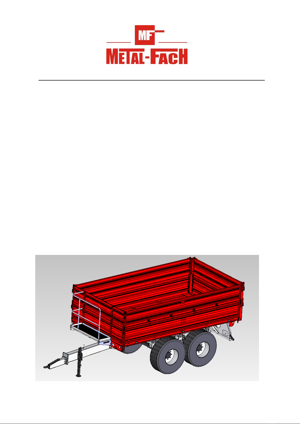
FARMING TRUCK TRAILER
Type T730/1-00 – 8 T
Type T730/2-00 – 10 T
Type T730/3-00 – 12 T

2
ORIGINAL INSTRUCTIONS
Edition I – year 2012
Trailer data
Vehicle type: farming truck trailer
Type designation: T730
Trade name: T730/1, T730/2 , T730/3 *
Trailer identication number1/:
Trailer manufacturer: METAL-FACH Sp. z o.o.
16-100 Sokółka
ul. Kresowa 62
Tel. no. +48 85 711 ..
Fax: +48 85 711 98 40
Sold by:
Address:
Tel./ Fa x:
Date of delivery:
Owner / User: Name:
Address:
Tel./ Fa x:
1/ The data is found on the trailer nameplate located on the trailer chassis front crosspiece
* - delete as appropriate
3
CE DECLARATION OF CONFORMITY
FOR THE MACHINE
„METAL-FACH” Sp. z o.o.
ul. Kresowa 62
16-100 SOKÓŁKA
which acts as the manufacturer
declares under sole responsibility that the following machine:
this declaration concerns, meets the following requirements:
- Directive 2006/42/EC OF THE EUROPEAN PARLIAMENT AND OF THE COUNCIL
dated 17 May 2006 on machines and the Resolution of the Minister of Economy
of 21 October 2008 concerning general requirements for machinery (Journal of Laws,
No. 199, item 1228);
The following harmonised standards were used for compliance evaluation:
PN-EN ISO 1853+A1: 2009 PN-EN ISO 4254-1:2009
PN-EN ISO 13857:2010 PN-EN ISO 12100:2011
- and the following standards: PN-ISO 3600:1998, PN-ISO 11684:1998; and the Resolution of
the Ministry of Infrastructure of 31 December 2002 on technical requirements for vehicles
and the scope of their necessary equipment (Journal of Laws 2003, issue 32 item 262 as
amended).
Safety Test Report no. MF/2/2012
Unit responsible for engineering documentation: METAL-FACH Engineering Department
This Declaration of Conformity becomes void and null if the machine design is changed
or modied in any manner without prior consent from the manufacturer.
Sokółka, 23.10.2010 President of the Management Board
Jacek Marek Kucharewicz
Farming truck trailer
T730- .........................................
year of manufacture: ........................................
serial number: ...................................................

4
Table of Contents
1. INTRODUCTION ............................................................................................................................ 5
1.1. Machine identication............................................................................................................. 6
1.2. Intended use............................................................................................................................. 7
2. GENERAL SAFETY RULES .......................................................................................................... 8
2.1. Symbols and nomenclature ..................................................................................................... 8
2.2. Obligatory notication ............................................................................................................ 9
2.3. General safety regulations of work and use ............................................................................ 9
2.3.1. Safety of operation ......................................................................................................... 9
2.3.2. Tyres ............................................................................................................................. 12
2.3.3. Pneumatic system ......................................................................................................... 12
2.3.4. Periodic maintenance................................................................................................... 12
2.3.5. Travelling on public roads ........................................................................................... 13
2.4. Warning/information signs and text on the trailer................................................................. 14
3. TECHNICAL CHARACTERISTICS. GENERAL DATA............................................................. 17
4. GENERAL DESCRIPTION OF DESIGN AND FUNCTION ...................................................... 19
4.1. Chassis................................................................................................................................... 19
4.2. Load surface .......................................................................................................................... 19
4.3. Load body hydraulic tipping mechanism .............................................................................. 20
4.4. Electrical system (signalling and warning) ........................................................................... 21
4.5. Braking system...................................................................................................................... 21
5. STORAGE, SALE AND SHIPPING TO USER ........................................................................... 23
6. OPERATION INFORMATION...................................................................................................... 24
6.1. Commissioning the trailer ..................................................................................................... 24
6.2. Loading the body................................................................................................................... 25
6.3. Travelling on public roads..................................................................................................... 26
6.4. Unloading .............................................................................................................................. 27
6.5. Decoupling from the tractor .................................................................................................. 28
7. SERVICING ................................................................................................................................... 29
7.1. Servicing instruction for adjusted trailer components........................................................... 29
7.1.1. Wheels – bearing clearance adjustment ...................................................................... 29
7.2. Brakes.................................................................................................................................... 30
7.2.1. Brakes – servicing the brake pneumatic system........................................................... 30
7.2.2. Brakes – servicing the brake hydraulic system ............................................................ 30
7.2.3. Brakes – adjustment of the braking system components.............................................. 30
7.2.4. Hydraulic brakes – operating principle....................................................................... 33
7.3. Wheels – tyres ....................................................................................................................... 34
7.4. Hydraulic system................................................................................................................... 34
7.4.1. Hydraulic system – servicing of the load body hydraulic tipping system .................... 34
7.4.2. Hydraulic system – adjustment of the load body hydraulic tipping mechanism.......... 34
8. TROUBLESHOOTING ................................................................................................................. 35
9. PERIODIC MAINTENANCE........................................................................................................ 36
9.1. Lubrication ............................................................................................................................ 36
9.2. Maintenance and servicing.................................................................................................... 37
10. DISPOSAL OF THE TRAILER..................................................................................................... 39
11. RESIDUAL RISKS ........................................................................................................................ 39

5
1. INTRODUCTION
This manual describes operation and servicing of the T730 trailer. The operating instructions
contain the information necessary.
If you require further information or particular problems arise which were not discussed
in detail in the operating instructions, the customer should request the information from the
manufacturer or the dealer. The crucial obligations of the manufacturer are stated in the warranty
document which species the complete and current regulations for warranty services.
METAL-FACH Sp. z o. o. reserves the right to introduce changes without prior notice
and without assuming any obligations resulting from those changes.
The T730 trailer has been designed for reliable and safe operation if used in accordance with
the operating instructions. Therefore before starting the machine we request that the users read
the following manual for thorough understanding of specic issues.
All operators of this trailer must understand the contents of the operating
instructions before commencing work.
This is intended to maintain proper operation of the trailer, safety of use and maximum
operating life. This is also the condition which ensures that your warranty rights are maintained.

6
1.1. Machine identication
In all correspondence, questions, and warranty issues, please state the type and identication
number of the trailer.
Trailer version 12 3 4 5 67 8 9
T730/1 T730/1 2012 7301112xxxxx 3500 15 KJ.. PL*xxxx*xx 11500 51/51
T730/2 T730/2 2012 7302112xxxxx 3540 17.64 KJ.. PL*xxxx*xx 13540 60.1/60.1
T730/3 T730/3 2012 7303112xxxxx 3600 17.64 KJ.. PL*xxxx*xx 15600 69.2/69.2

7
The identication data is found on the trailer nameplate located on the trailer chassis front
crosspiece. The trailer serial number is stamped on the nameplate and under the plate, directly
on the machine frame.
The manual is a part of the trailer’s essential equipment.
Hint: Note down the type and serial number of your trailer. Please give this number every
time you contact your supplier.
The manual constitutes a part of the machine's equipment.
1.2. Intended use
The trailer is intended for transport of crops and other bulk or loose materials within a farm
and on public roads.
The trailer is unloaded manually or by tipping the load body to the rear or to the sides. The
trailer is designed for coupling with farming tractors of varying power ratings, equipped with a
external power hydraulic system, a power outlet for the electrical lighting and warning systems
and the braking system of hitched machines, and a transport hitch.
Do not use this trailer to carry fuel, gas cylinders and similar due to the compliance
requirements for transport of hazardous materials.
• Do not use the trailer to transport: fuel, gas cylinders, or toxic materials that may cause
environmental pollution. The manufacturer shall not be liable for any resulting damage as it
is solely incurred by the owner.
• The trailer shall only be used by persons who have understood the operating manual and
who have been trained in hazards and rst aid for accident victims.
• Follow all applicable laws for accident prevention and any other recognised rules of
engineering safety, work medicine and road trafc safety.
• The manufacturer shall not be liable for damage from any unauthorised modications of this
trailer's design.

8
1.3 Equipment
The basic equipment of each trailer includes:
- the operating instructions manual;
- the warranty card with warranty conditions;
- the bracket for the sign "slow-moving vehicle";
- the two-line pneumatic brakes with adjustable braking force;
- the parking brake;
- the lighting installation;
- semi-elliptic spring suspension
- folded walls, front and rear
On customer's request (additional costs incurred), the manufacturer may equip the trailer
with the slow-moving vehicle sign and a reective warning triangle.
2. GENERAL SAFETY RULES
2.1. Symbols and nomenclature
WA R N I N G! This warning sign in the operating instructions means that special
caution shall be exercised due to hazards to persons and potential
damage.
IMPORTANT! Failure to comply with these guidelines may result in damage of
equipment or its components.
INFORMATION!
It is important to carefully follow these notes and guidelines.
Qualied persons are persons who perform the required tasks by always using their education,
experience and training, as well as their understanding of standards, denitions, accident
prevention regulations and operating conditions; hence they are also capable of identifying and
avoiding potential hazards.
Among others, these persons are also required to understand rst aid measures for the
injured (e.g. by wounding).
The term "operation" includes settings, starting (preparation for use) and operation (starting,
commissioning, powering off, etc.).
The term "maintenance of proper condition" includes checks and care (control, adjustments),
servicing and repairs (troubleshooting).
Note all other (specially highlighted) indications for transport, assembly, operation, servicing
and technical data (in the operating instructions, production records and on the trailer itself). It

9
is all the same essential due to the potential (direct and indirect) hazards and their consequences
being severe damage of human health and property.
2.2. Obligatory notication
When the trailer is transferred to another user, the operating instructions shall be transferred
as well, whereas the receiving user must undergo training according to the instructions.
2.3. General safety regulations of work and use
Before each start of work, inspect the trailer for work safety.
1. Aside from the guidelines in these operating instructions, follow the general regulations for
safety and accident prevention.
2. The afxed information and warning signs and text indicate important guidance for safe
operation. Follow it for your safety.
3. Start the trailer only when all required equipment is connected and secured against
unintended release or opening (e.g. the hitch and tow bar system, couplings, etc.).
4. Understand all equipment and controls, as well as their functions, before work. It is too late
to learn that during work.
5. The trailer must not be used by persons who are under the inuence of alcohol and/or other
substances, and/or not trained or suitably licensed to operate motor vehicles.
2.3.1. Safety of operation
1. All work safety information shall be given to all other users of the trailer.
2. Check the direct environment (for children and bystanders) before start. Pay particular
attention when visibility is poor.
3. Do not remain on the trailer in motion, when coupling the trailer with a tractor and when
loading or unloading the trailer.
4. After unloading the trailer, lower the load body completely. Never leave the trailer unattended
with its load body raised.
5. Enter the trailer only when it has completely stopped and with the tractor engine stopped.
6. Lift and lower the load body only from the driver's seat.
7. Hitch the trailer according to regulations, couple only with recommended equipment and
secure the tow bar hitch-ring to the tractor transport hitch.
8. Exercise extreme caution when coupling/decoupling the trailer with/from the tractor.
9. When installing and removing supports, security/safety equipment and ladders, these types
of equipment must always be positioned to ensure safety to operators.
10. Follow the maximum permissible axle loads, total weight and transport dimensions.
11. Do the following checks: coupling and functional test of brakes and lights, inspect the slow-
moving vehicle sign, and check other protective devices.

10
12. Do a functional test of lights and brakes before driving. Also prepare the trailer as
recommended in Section "Travelling on public roads".
13. Mind the changes in vehicle behaviour, steerability and braking efciency
1. due to the hitched trailer and its load.
14. When towing the trailer, mind the layout of loads and/or inertia, especially when the load is
unevenly distributed.
15. Do not remain within the range of discharged load.
16. Start the hydraulic lift (tipping) of the load body only when:
- the trailer is coupled with the tractor, AND
- the trailer is parked on a hard and level ground, AND
- when no persons remain in the unloading area, AND
- when the tractor's axis is aligned with the trailer, AND
- when the machines are at a safe distance from all power lines, AND
- there are no strong gusts of wind.
If it is necessary to unload to the rear while parking on a slope, the trailer with the tractor must
be in the uphill direction. If unloading to the side on a slope, tilt the load body in the opposite
to the trailer's direction of gradient.
17. During all work with the raised load body, secure it from falling with the support that has
been delivered with the trailer. Turn off the tractor engine and remove the ignition key.
18. Be careful to avoid crushing of ngers and hands during opening and closing of the load
body walls.
19. Mind the warnings of crush and cut hazard areas when starting the work with trailer. There
is a risk of injury when coupling/decoupling the trailer with/from the tractor. Hence when
coupling/decoupling, do not enter between the trailer and the tractor or stand behind the
trailer if the trailer is not secured with wheel chocks or the parking brake.
20. No person is allowed to remain between the trailer and the tractor if the vehicle is not
secured against rolling with the parking brake and/or wheel chocks.
21. When parked, secure the tractor and the trailer against rolling.
22. Do not drive with the lifted load body.
23. When raising the load body, maintain a safe distance from power lines. The C.2.30. sign acc.
to PN-ISO 11684:1998 on the front wall of the trailer warns of power lines.
24. During all servicing or repair works which require lifting the load body, the body must be
empty and secured with the mechanical support against accidental falling.
25. Always adapt your driving speed to the conditions. Avoid rapid turns when driving uphill or
downhill.
26. Maintain a safe distance from the U-turn range of the tractor and trailer train.
27. Ensure adequate visibility (with the help of a signalling person, if necessary) when driving
in reverse.
28. When cornering, mind the inertia of the trailer.

11
29. Additional protection for the transported load on the trailer (chains, tarpaulin, plastic sheet,
nets, transport straps, etc.) may be applied only with tractor engine off and the ignition key
removed.
30. Remove functional disturbances of attachments only with the engine turned off and the
ignition key removed.
31. Enter the load body surface only after turning off the drive and stopping the tractor engine.
Remove the ignition key.
32. Always turn off the engine and remove the ignition key before exiting the tractor. Engage
the parking brake and secure the trailer with the wheel chock.
33. When travelling on public roads, the permissible axle set load of the T730/1 trailer
must not exceed 102 kN, the permissible axle set load of the T730/2 trailer must not
exceed 120.1 kN each, and the permissible axle set load of the T730/3 trailer must not
exceed 138.4 kN.
34. The maximum permissible pressure of the hydraulic system is 16 MPa.
35. The maximum permissible pneumatic pressure of the single-line system is 0.63 MPa or 0.8
MPa for the two-line system.
36. Prepare the trailer for work (connect the pneumatic and hydraulic hoses, etc.) with the tractor
engine off and the ignition key removed.
37. The manufacturer delivers the trailer completely assembled.
38. All hydraulic lines must be replaced every 6 years.
39. Noise – the equivalent sound pressure emission corrected by A characteristics (LpA) does
not exceed 70 dB.

12
2.3.2. Tyre s
1. Make sure to secure the trailer against accidental movement when servicing the tyres.
2. The wheels and tyres shall be repaired by trained personnel with adequate tools.
3. Regularly check the tyre pressure. Maintain the recommended pressure values.
4. Protect the tyres against sunlight during prolonged parking of the trailer.
5. Replace the wheels with the trailer empty, if possible.
2.3.3. Pneumatic system
1. The pneumatic system is under high pressure.
2. When connecting the pneumatic lines with the pneumatic system of the tractor, ensure that
the valves on the tractor and the trailer are depressurised.
3. Periodically inspect the pneumatic connections. Replace all damaged and aged parts
immediately. Replace the lines as recommended in the manufacturer technical requirements.
Replace hoses every ve years unless damage is found earlier.
4. Before attempting any work on the pneumatic system, depressurise it and turn off the tractor
engine.
5. All repair work on the pneumatic system may only be performed by specialist services of
the trailer's manufacturer.
2.3.4. Periodic maintenance
1. All maintenance, repair and cleaning operations, as well as troubleshooting must be
performed after turning the drive and the tractor engine off. Remove the ignition key.
2. Inspect all bolts and nuts periodically and retighten if necessary. Replace regular bolts only
with the bolts of the same quality and strength ratings.
3. When servicing under the lifted and tipped AND unloaded load body, always secure the
body with the support supplied with the trailer.
4. Use proper tools and safety gloves when replacing any parts.
5. After completing your work, thoroughly clean the trailer to leave no remains of the load on
the body.
6. Isolate the continuous power supply before arc welding and/or working on the electrical
system.
7. The safety/protection equipment wears out, which requires periodic adjustments, inspection
and replacement when necessary.
8. Use only the original spare parts recommended by METAL-FACH Sokółka.
9. Store the trailer in sheltered areas (preferably on level and hardened ground) and in a manner
which prevents injuries of people and animals.
10. Release all worn out parts to authorised recycling points while following all applicable
environmental protection requirements.

13
2.3.5. Travelling on public roads
Before departing, check that the trailer lighting is working and that the trailer identication
is complete.
Follow the trafc code regulations when travelling on public roads.
1. Exceeding the permissible payload and driving speed may damage the trailer and compromise
trafc safety.
2. Do not exceed the permissible driving speed of 40 km/h.
3. The trailer is designed for operation at grades of 8o maximum.
4. When travelling on public roads, the trailer must feature a reective warning triangle, and the
slow-moving vehicle sign in the trailer bracket located on the chassis frame rear crosspiece
(included with the trailer).
5. Do not leave the loaded trailer on slopes and when it is not secured from rolling. Secure the
trailer by engaging the parking brake and chocking the wheels. Also bind the transported
load with transport straps.
6. The maximum transport (transit) speed is 30 km/h.
14
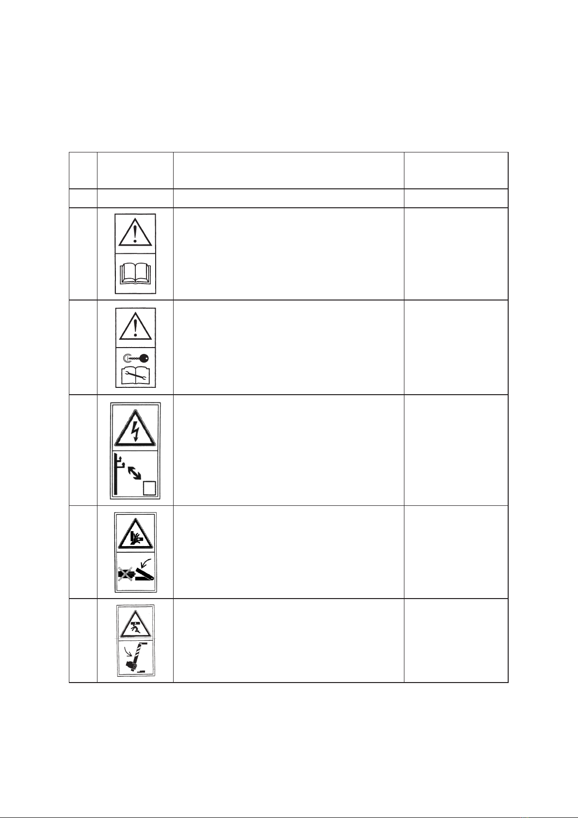
2.4. Warning/information signs and text on the trailer
The warning signs and text on the trailer must not be removed. They are intended for safe
handling of the trailer. If any information label is damaged or removed, order a spare one. Text
and symbol label stickers are available at service agents or at the trailer manufacturer.
Table 1
Item Safety
Symbol Meaning of the symbol (sign) or text Location on the
machine
12 3 4
1Read the operating instructions
On the load
body frame front
crosspiece
2Turn off the engine and remove the ignition
key before servicing or repairs
On the load body
front crosspiece
3Keep a safe distance from power lines On the load body
front crosspiece
4Do not reach into the crushing area if the parts
may move
On side walls/
panels
5Install the support before entering the
hazardous area
On the chassis side
frame member, at
the support
15
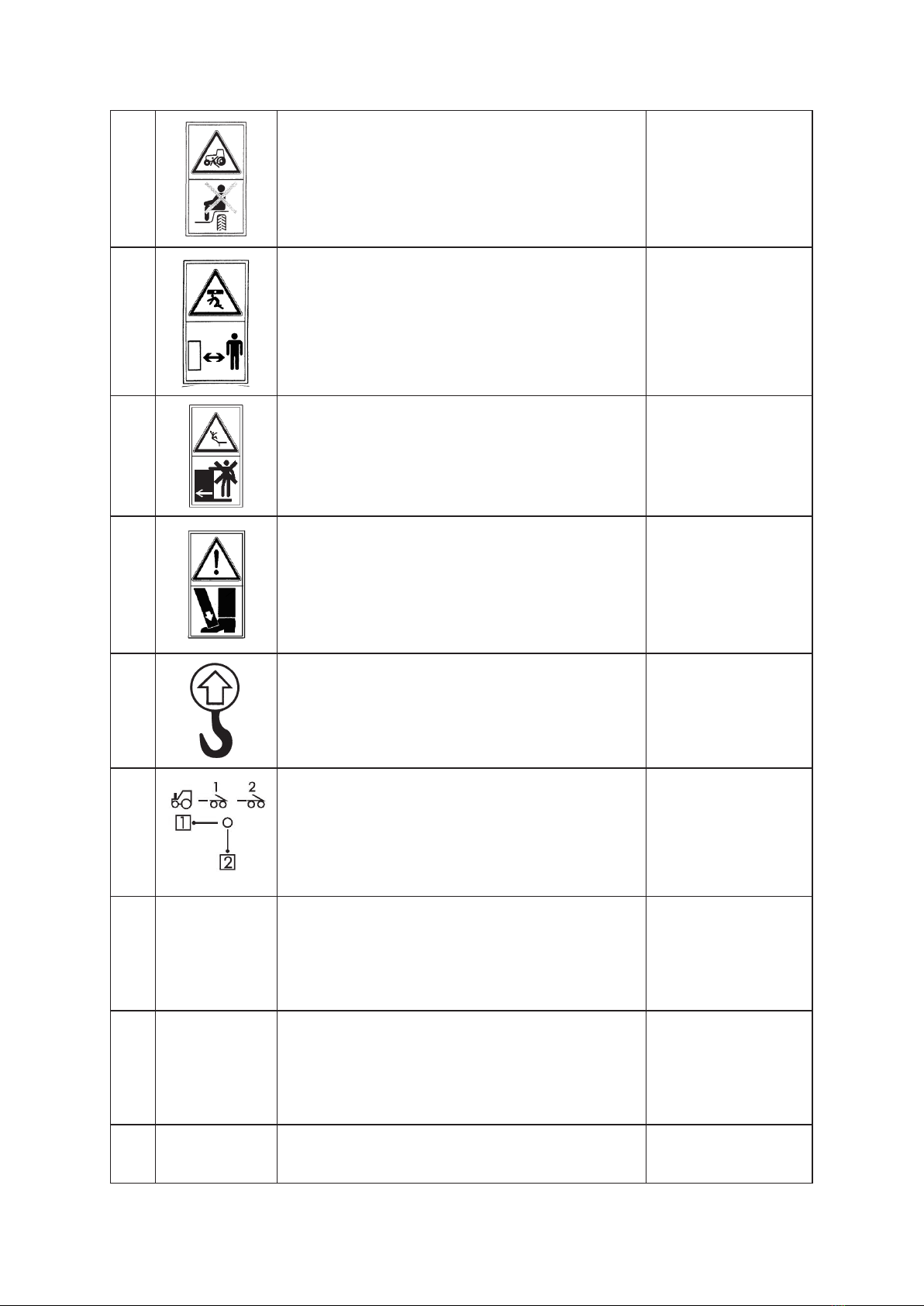
6Do not ride on the machine – use the passenger
seat only
On the load body
front wall
7 Keep a safe distance from the machine On the load body
front wall
8Do not stand on ladders and platforms while
the tractor is moving At the ladder
9Feet (toes) crushing hazard.
Force applied from above On the tow bar
10 Lifting point
On the chassis
frame side
members
11 DCV lever setting At the directional
control valve
12
Caution!
Do not perform any checks or servicing under
the loaded or tilted load body without the
support
At the support
13
Caution!
Do not remain within the range of discharged
loads
Do not enter the trailer when it is hauled
On the load body
front wall
14 "Load capacity 8 t" On the load body
left and right wall

16
15 "Load capacity 10 t" On the load body
left and right wall
16 "Load capacity 12 t" On the load body
left and right wall
17 Maximum hydraulic system pressure: 16 MPa On the oor frame
front crosspiece
18
Maximum pneumatic system pressure:
0.6 MPa, single-line system; 0.8 MPa, two-line
system
On the load body
front wall
19 - "550 kPa" – 385/65 R22.5 tyres
(BANDEMARKT) Over the wheels
20 - "425 kPa" – 14.5/80-18 12PR tyres (MITAS) Over the wheels
21 15 kN max On the hitch
22 17.64 kN max On the hitch
NOTE!* The trailer user is required to keep the warning symbols and text
on the trailer legible during its entire operating life. If damaged or
destroyed, replace with new ones.

17
3. TECHNICAL CHARACTERISTICS. GENERAL DATA
Table 2
Item Contents
I General data
1Vehicle type – farming trailer
Manufacturer – METAL-FACH Sp. z o.o.
16-100 Sokółka, ul. Kresowa 62
2 Type (model) – T730
4 Body type – platform
5 Nameplate location – chassis frame front crosspiece
6S/N stamping location – on the nameplate and underneath
II Dimensions and weight
T730/1 – 8T T730/2 – 10T T730/3 – 12T
7. Length, mm 6565 6565 6565
8. Width, mm 2550 2550 2550
9. Height, mm
(with top
section)
1750 (2250) 1850 (2350) 1850 (2650)
10. Number of
axles, pcs.
2 2 2
11. Wheel base,
mm
1200 1200 1200
12. Wheel track,
mm
1900 1900 1900
13. Loading
room
size
- length, mm 4505 4505 4505
- width, mm 2402 2402 2402
- height (with
top section),
mm
500 (1000) 600 (1100) 600 (1400)
14. Loading
surface height,
mm
1300 1300 1300
15. Tow bar
oscillation
height, mm
430-850 430-850 430-850
16. Tow bar hitch-
ring diameter,
mm
45 45 45
17. Vehicle ramp
clearance, mm
480 480 480
18. Vehicle kerb
weight, kg
3500 3540 3600
19. Permissible
vehicle overall
weight, kg:
1150 0 13540 15600
- on axle set,
kg
10200 12010 13840
20. Maximum
axle load, kN
- on axle set,
kN
102 120.1 138.4

18
21. Permissible
vehicle load
capacity, kg
8000 10000 12000
IV Suspension
22. Suspension
type
dependent, with springs dependent, with springs dependent, with springs
23. Spring
component
type and style
longitudinal 2-leaf
parabolic springs
longitudinal 2-leaf
parabolic springs
longitudinal 2-leaf
parabolic springs
V Wheels and tyres
24. Number of
wheels, pcs.
4 4 4
25. Wheel disk
size
11.75x 22.5 11x18 11.75x 22.5 11x18 11.75x 22.5 11x18
26. Tyre size and
PR number
385/65R22.5 14.5/80-18
12 PR
385/65
R22.5
14.5/80-18
12 PR
385/65
R22.5
14.5/80-18
12 PR
- tyre
manufacturer
Bandemarkt Mitas Bandemarkt Mitas Bandemarkt Mitas
27. Tyre pressure,
bar
5.5 4.25 5.5 4.25 5.5 4.25
VI Braking system
28. Service brake;
- type mechanical, drum-type mechanical, drum-type mechanical, drum-type
- control pneumatic, positive
pressure,
two-line brake system;
hydraulic
pneumatic,
positive pressure, two-line
brake system;
hydraulic
pneumatic,
positive pressure, two-line
brake system;
hydraulic
- no. of wheels
operated
4 4 4
29. Parking brake
- type mechanical, drum-type mechanical, drum-type mechanical, drum-type
- control manual, by a screw gear manual, by a screw gear manual, by a screw gear
- operated
components
2 front axle wheels 2 front axle wheels 2 front axle wheels
VII Electrical system
30. Voltage rating,
V
12, feed by the driving
tractor
12, feed by the driving
tractor
12, feed by the driving
tractor
VIII Operating data
31. Maximum
transport
speed, km/h
30 30 30
32. Maximum
speed, km/h
40 40 40
IX Additional information
33. Other
information:
- driving
tractor
45 kW minimum 55 kW minimum 65 kW minimum

19
4. GENERAL DESCRIPTION OF DESIGN AND FUNCTION
The T730 is a metal design with open load surface. The trailer features a pneumatic or
hydraulic service brake and a parking brake that is manually operated via a screw gear, actuating
the friction components of the rear axle service brake.
The trailer features a complete signalling and warning system (an electrical system and
reective lights).
The trailer is also suitable for transport on public roads.
The trailer is manufactured in accordance with Directive 2006/42/EC and the following
standards: PN-EN ISO 4254-1:2009, PN-EN ISO 1853+A1:2009, PN-EN ISO 13857:2010, PN-
EN ISO 12100:2011.
4.1. Chassis
The trailer chassis is composed of the following subassemblies: bottom frame, tow bar,
wheel sets and suspension components. The bottom frame and the tow bar are welded structures
made of steel sheet and proles.
The trailer wheel sets are composed of: the axles (tandem style), land wheels and wheel
brakes.
The axles are made of thick-wall pipes terminated with plugs on which land wheel hubs are
set by cone bearings. They are single wheels equipped with drum brakes with the jaws actuated
by mechanical expander cams.
The trailer axle suspension consists of steel semi-elliptic leaf springs attached to the turntable
frame and the bottom frame by pins and sliders. The wheel sets are attached to the springs by
bolts.
4.2. Load surface
The loading space of the trailer is made of the following:
The top frame (box frame) that is set on the bottom frame (chassis frame) in articulated seats
secured by pins which serve as pivots during tilting (tipping) of the top frame (load body/box).
The side walls/boards and their top sections are singular components. Each component
features a separate set of locks for closing and opening of individual wall and top sections
independent of each other and in any order. These design solutions increase functionality and
facilitate operation of the trailer.
The wall and top section locks are secured against accidental release.

20
4.3. Load body hydraulic tipping mechanism
The hydraulic mechanism is designed for automatic unloading of the trailer by tipping the
load body backwards or sideways. The hydraulic tipping system is fed with oil from the tractor
hydraulic system.
The hydraulic system includes: the coupling valve plug, hydraulic lines, the single-action
hydraulic actuator, the cut-off valve, and connecting and fastening components. Figure 1 shows
the diagram of the load body hydraulic tipping system. The lifting and lowering of the load
body is controlled by the DCV in the tractor hydraulic system.
INFORMATION!
• The cut-off valve limits the load body tilt angle during tipping to
the sides. The valve is pre-adjusted by the trailer manufacturer.
Do not adjust it on your own.
Fig. 1 Diagram of the load body hydraulic tipping system
1 - hydraulic actuator; 2 - hydraulic lines; 3 - cut-off valve;
4 - cut-off valve control cable; 5 - coupling valve plug.
This manual suits for next models
2
Table of contents
Other Metal-Fach Utility Vehicle manuals


Popular Utility Vehicle manuals by other brands


Husqvarna
Husqvarna HUV 4213-G owner's manual

Roketa
Roketa GK-17 user manual

LONCIN
LONCIN RANCHPONY 700 owner's manual

Montracon
Montracon MT45 Operator's handbook

Textron Specialized Vehicles
Textron Specialized Vehicles Cushman HAULER 800X ELiTE 2019 owner's guide

Avenir
Avenir CARGO TRA ILER owner's manual