TIMBCO TF800 Reference manual

Introduction
0.1
Form M247
Introduction
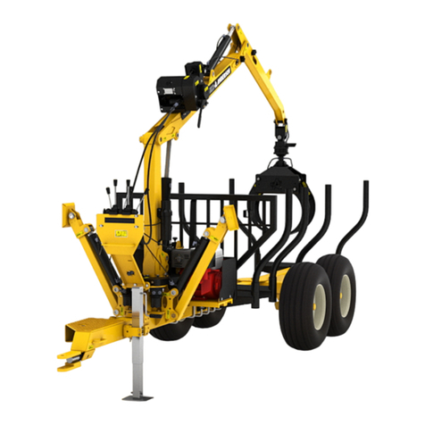
TIMBCO TF800 Hydro-Skidder
“Built By Loggers
For Loggers”
TIMBCO, Inc.
Shawano, WI
00382

Introduction 0.2
Introduction
The purpose of this manual is to familiarize the new
owner/operator with the many features of the
TIMBTEC TF800 Hydro-Skidder so that they may
become proficient in the machine’s operation and
periodic maintenance. This manual is provided with
detailed operating and maintenance instructions as
well as safety information and equipment data.
Throughout this manual, references are made to the
front, rear, left and right sides of the machine.
Determine front, rear left and right when sitting in
the operator’s seat and looking out over the fuel
tank.
The instructions and procedures in this manual
cover the basic machine model furnished with the
most commonly used options. Pictorial information
in some areas may vary slightly from the actual
machine on hand. This variation, however, does not
have any impact on the accuracy of the written
information.
The information contained in this manual is current
at the time of publication, however, continuing
product improvement may result in changes to the
machine which are not covered. Should you require
information regarding such changes or any other
information on the machine, please contact your
TIMBTEC dealer.
Form M247
Figure 1: Directional Reference (Shown in forwarder configuration)
Rear
Left Right
Front
Fuel Tank

Introduction
0.3
TIMBTEC
Nomenclature - TF800 Forwarder
Form M247
Figure 2: General Nomenclature - TF800 Short Wood Forwarder
Hydraulic Oil Tank
Log
Rack
Log
Stake (8)
Operator’s Cab
(ROPS/FOPS/OPS)
Main Boom
Loader
Bucket
Stick
Boom
Floating
Bunk
Engine Compartment Emergency
Escape Hatch
Frame Articulation
Bearing & Joint
(2) N.A.F. Tandem Double Bogie Axle
(Several Tire Combinations Available)
Fuel
Tank
(2) Steer
Cylinder
Caliper
Brake

Introduction 0.4 Form M247
TIMBTEC
Nomenclature - TF800 Clam Bunk Skidder
Figure 3: General Nomenclature - TF800 Clam Bunk Skidder
Hydraulic Oil Tank
Clam
Bunk
Caliper
Brake
Clam
Bunk
Operator’s Cab
(ROPS/FOPS/OPS)
Main Boom
Loader
Bucket
Stick
Boom
Engine Compartment
Emergency
Escape Hatch
Frame Articulation
Bearing & Joint
(2) N.A.F. Tandem Double Bogie Axle
(Several Tire Combinations Available)
(2) Steer
Cylinder
Fuel
Tank

Introduction
0.5
Form M247
Figure 4: Upper Turntable Nomenclature - Side View (Less Cab and Booms)
Return Filter Guard (Removed)
00017
Radiator Fill Spout Access Cover (Open)
00016
Louvered Swing-Out Radiator Guard (Open)
00022
Slotted Engine Pivot Guard (Open)
00021
Hydraulic
Oil Tank Air Cleaner
/ Muffler Area
Engine Compartment
ROPS Panel
Swing Bearing
Swing
Motor
Continuous
Rotation Swivel

Introduction 0.6 Form M247
Figure 5: Upper Turntable Nomenclature - End View (Less Cab and Booms)
Perforated Swing-Out Engine Guard (Open)
00001
Main Boom
Pivot Point
Hydraulic
Oil Tank
Swing
Motor
Engine Compartment
ROPS Panel
Swing Bearing
Boom Side
Pump Panel
Upper Turntable
Base Plate
Swing-Out Pump Access Guard (Open)
00279

Figure 6: Cab Nomenclature - Side View
Introduction
0.7
Form M247
Skylight
Door
Latch
Halogen
Lights
Flush Mount
Exterior Lights
Cab
Door
Flush Mount
Exterior Light
A/C Condensor Fan
& Optional Fire
Suppression System
Mounting Position
Swing-Out Control Valve Guard (Open)
00420

Introduction 0.8 Form M247
Figure 7: Cab Nomenclature - End View
Lift Eye
Air Conditioner Condenser Access
Cover (Open)
00420
Emergency
Escape Hatch
Swing-Out
Control Valve
Guard

Introduction
0.9
Form M247
Figure 8: Loader Boom Nomenclature
Main Boom
Boom Elbow
Pivot
Stick Boom
Cylinder
Main Boom
Tubelines
Main Boom
Cylinder
Stick
Boom
Loader Bucket
(Hultdins Supergrip 360S Shown)
Main Boom
Pivot Point
Stick
Boom
Tubelines

Introduction 0.10 Form M247
Figure 9: Front Frame Nomenclature
Swing Bearing
Mounting
Surface
N.A.F. Tandem
Bogie Axle
(2) 28L-26
Tires
Transfer Case & Drive Motor Access
Covers (Open)
00436
Frame
Articulation
Bearing
Mounting
Surface
Fuel
Tank

Introduction
0.11
Form M247
Figure 11: Rear Frame Nomenclature
Differential & Upper Brake Access
Cover (Open)
00432
Drive Shaft, Steer Cylinder & Steer Box
Access Covers (Open)
00433
Floating
Bunk Rear
Frame
N.A.F. Tandem
Bogie Axle
(2) 28L-26
Tires

Introduction 0.12 Form M247
Figure 12: Clam Bunk Nomenclature
Clamp Arms
Deck Plate
Front
Skirt Guard
Slew Ring
Mounting
Base
Mounting
Base
Rear Skirt
Guard

Introduction
0.13
Form M247
Important Model
& Serial Numbers
For quick reference, use the lines provided below
each illustration to record important manufacturer,
model and serial number information for your
TIMBTEC Hydro-Skidder and its major
components. These serial numbers will allow your
TIMBTEC dealer to correctly identify your machine
and its components when filling replacement parts
orders or providing service information.
Engine (Typical)
Manufacturer__________________________________
Model_____________________________________
S/N#______________________________________
TIMBTEC Hydro-Skidder
Model__________
S/N#______________________________________
Tandem Bogie Axles
Manufacturer__________________________________
FRONT:
Model__________
S/N#______________________________________
REAR:
Model__________
S/N#______________________________________
00007
00386
00408
Transfer Case (Typical)
Model__________
S/N#______________________________________
00283
Wheel Drive Pump
(May be installed with the SN# tag on bottom face)
Manufacturer__________________________________
Model_____________________________________
S/N#______________________________________
00281

Introduction 0.14 Form M247
Swing Motor
Manufacturer__________________________________
Model_____________________________________
S/N#______________________________________
00024
Loader Bucket
Manufacturer__________________________________
Model_____________________________________
S/N#______________________________________
Loader Pump
(Installed with the SN# tag on bottom face)
Manufacturer__________________________________
Model_____________________________________
S/N#______________________________________
00032
Wheel Drive Motor
(Installed with the SN# tag on bottom face)
Manufacturer__________________________________
FRONT:
Model__________
S/N#______________________________________
REAR:
Model__________
S/N#______________________________________
00282
00280
Loader Bucket Rotator
Manufacturer__________________________________
Model_____________________________________
S/N#______________________________________
00280

Introduction
0.15
Form M247
Clam Bunk
Manufacturer__________________________________
Model_____________________________________
S/N#______________________________________
00284

Introduction 0.16 Form M247
THIS PAGE LEFT BLANK FOR NOTES

Safety - General Information
1.1.1
Form M004
Section 1.1
Safety -
General Safety Information
General . . . . . . . . . . . . . . . . . . . . . . . . . . . . . . . . . . . . . . . . . . . . . . . 1.1.2
“Safety Alert” Symbol . . . . . . . . . . . . . . . . . . . . . . . . . . . . . . . . . . . . 1.1.2
Understanding Signal Words . . . . . . . . . . . . . . . . . . . . . . . . . . . . . . . 1.1.2
The Careful Operator . . . . . . . . . . . . . . . . . . . . . . . . . . . . . . . . . . . . 1.1.3

Safety - General Information 1.1.2
General
TIMBCO’s policy is to produce products that are
safe and reliable. However, even when using well
engineered equipment, there will always be an
element of risk in heavy equipment operation.
Most accidents involving heavy equipment
operation, maintenance or service result from
failure to follow basic safety rules and precautions.
To minimize the risks and promote safety at all
times, the safety group in this manual details a
number of safety rules which should always be
followed and obeyed.
Study all the safety messages carefully, remember
them and apply them when operating, maintaining
or servicing this machine.
“Safety Alert” Symbol
The “Safety Alert” symbol is used where applicable
throughout the text and on the machine to
indicate important personal safety measures and
equipment cautions. Carefully read, understand
and follow these instructions to prevent hazardous
situations, possible injuries to personnel or damage
to the machine.
Understanding Signal Words
In this manual and on the safety decals installed on
the machine, the “Safety Alert” symbol is always
accompanied by a signal word to identify the hazard
leve. Understand the signal words DANGER,
WARNING, and CAUTION.
Identifies the most serious safety hazards
where failure to follow the safety message
would result in high probability of death or
serious personal injury.
Identifies that a safety hazard exists where
failure to follow the safety message can
result in death or serious personal injury if
proper precautions are not taken.
Identifies that a hazard exists where failure
to follow the safety message can result in
personal injury or equipment damage if the
proper precautions are not taken.
The signal words DANGER, WARNING and
CAUTION are used to identify personal safety
hazards and some equipment cautions. In this
manual, the signal word NOTICE is also used to
identify hazards that may damage the machine or
its components.
Follow procedures outlined to avoid damage to
the machine or its components as a result of
use or improper procedures.
Form M004
DANGER
WARNING
CAUTION
NOTICE
Figure 1 - Safety Alert Symbol

Safety - General Information
1.1.3
The Careful Operator
The careful operator is one who studies,
remembers and applies the basic safety rules and
all safety messages found in the manuals and on
the equipment being operated, maintained or
serviced. This person also has the required
training, skills and tools to operate this machine
and/or perform the required maintenance and
service procedures.
TIMBCO cannot anticipate every possible
circumstance where a potential hazard may exist.
Therefore, the safety messages and equipment
cautions found in this manual and on the
machine are not all inclusive. If an operating
technique, maintenance or service procedure, tool,
etc... not specifically recommended by TIMBCO is
used, it is your responsibility to insure it is safe for
yourself and others. You should also be sure the
machine will not be damaged or made unsafe by the
operation, maintenance procedures or service
procedures you choose.
WHEN IT COMES TO SAFETY, NOTHING WILL
EVER REPLACE A CAREFUL OPERATOR.
Form M004
SAFETY FIRST !

Safety - General Information Form M004
THIS PAGE LEFT BLANK FOR NOTES
Table of contents
