Metal-Fach T735 User manual
METAL-FACH Sp. z o.o.
16-100 Sokółka, ul. Kresowa 62
Tel. no. +48 85 711 98 40
Fax: +48 85 711 90 65
OPERATING INSTRUCTIONS
FARMING TRAILER
TIPPER
Type T735

EDITION I – year 2011
Trailer data:
Vehicle type: mono-axial farming truck trailer
Commercial designation:
Type designation: T735
Trailer identication number1/:
Trailer manufacturer: METAL-FACH Sp. z o.o.
16-100 Sokółka
ul. Kresowa 62
Tel. no. +48 85 711 98 40
Fax: +48 85 711 90 65
Sold by:
Address:
Tel./Fax:
Date of delivery:
Owner / User: Name:
Address:
Tel./Fax:
HINT: Note down the type and serial number of your trailer. Please supply this number every
time you contact your dealer.
1) The data is found on the trailer nameplate located on the trailer right frame side member


Operating instructions. T735 farming trailer 4
CE DECLARATION OF CONFORMITY
FOR THE MACHINE
METAL-FACH Sp. z o. o.
ul. Kresowa 62
16-100 SOKÓŁKA
which acts as the manufacturer
declares under sole responsibility that the following machine:
this declaration concerns, meets the following requirements:
- Directive 2006/42/EC OF THE EUROPEAN PARLIAMENT AND OF THE COUNCIL
dated 17 May 2006 on machines and the Resolution of the Minister of Economy of
21 October 2008 concerning general requirements for machinery (Journal of Laws,
issue 199 item 1228);
The following harmonised standards were used for compliance evaluation:
PN-EN ISO 1853+A1:2009 PN-EN ISO 4254-1:2009
PN-EN ISO 13857:2010 PN-EN ISO 12100:2011
- and the following standards: PN-ISO 3600:1998, PN-ISO 11684:1998; and the Resolution of
the Ministry of Infrastructure of 31 December 2002 on technical requirements for vehicles
and the scope of their necessary equipment (Journal of Laws 2003, issue 32 item 262 as
amended).
Safety Test Report No. LBC/48/11
Unit responsible for engineering documentation: METAL-FACH Engineering Department
This Declaration of Conformity becomes void and null if the machine design is changed
or modied in any manner without prior consent from the manufacturer.
Sokółka, 23.12.2010 President of the Management Board
Jacek Marek Kucharewicz
Farming truck trailer
type/model: T735-...................................
serial number:.................................................
year of manufacture:......................................

Operating instructions. T735 farming trailer 5
Nameplate
In all correspondence, questions, and warranty issues, please state the type and identication
number of the trailer.
The identication data of the trailer is found on the nameplate located on the load body front
crosspiece. The serial number is stamped on the nameplate and underneath.
The manual is a part of the trailer’s essential equipment.
Nameplate
Serial number
Nameplate

Operating instructions. T735 farming trailer 6
TABLE OF CONTENTS
1. INTRODUCTION ...................................................................................................................... 7
1.1. Intended use ................................................................................................................................ 7
1.2. Equipment ................................................................................................................................... 8
2. GENERAL SAFETY RULES..................................................................................................... 8
2.1. Symbols and nomenclature ......................................................................................................... 8
2.2. Obligatory notication ................................................................................................................ 8
2.3. General safety regulations of work and use ................................................................................ 8
2.3.1. Safety of operation ...................................................................................................................... 9
2.3.2. Tyres...........................................................................................................................................11
2.3.3. Hydraulic and pneumatic systems..............................................................................................11
2.3.4. Periodic maintenance .................................................................................................................11
2.3.5. Travelling on public roads ........................................................................................................ 12
2.4. Warning signs and text on the trailer......................................................................................... 12
3. TECHNICAL CHARACTERISTICS....................................................................................... 14
4. GENERAL DESCRIPTION OF DESIGN AND FUNCTION................................................. 16
4.1. Chassis ...................................................................................................................................... 16
4.2. Load body ................................................................................................................................. 16
4.3. Load body hydraulic tipping mechanism.................................................................................. 17
4.4. Electrical system (signalling and warning)............................................................................... 17
4.5. Support foot............................................................................................................................... 18
4.6. Braking system.......................................................................................................................... 18
5. STORAGE, SALE AND SHIPPING TO USER ...................................................................... 19
6. OPERATION INFORMATION................................................................................................ 20
6.1. Commissioning the trailer......................................................................................................... 20
6.2. Loading the body ...................................................................................................................... 20
6.3. Travelling on public roads ........................................................................................................ 21
6.4. Unloading.................................................................................................................................. 21
6.5. Decoupling from the tractor...................................................................................................... 21
7. SERVICING.............................................................................................................................. 22
7.1. Servicing instruction for adjustable trailer components ........................................................... 22
7.2. Brakes........................................................................................................................................ 23
7.2.1. Brakes – servicing the brake pneumatic system ....................................................................... 23
7.2.2. Brakes – adjustment of the braking system components .......................................................... 23
7.3. Hydraulic system....................................................................................................................... 24
7.3.1. Hydraulic system – servicing of the load body hydraulic tipping system ................................ 24
7.3.2. Hydraulic system – adjustment of the load body hydraulic tipping mechanism ...................... 25
7.4. Wheels – tyres........................................................................................................................... 25
8. TROUBLESHOOTING............................................................................................................ 25
9. PERIODIC MAINTENANCE.................................................................................................. 26
9.1. Lubrication................................................................................................................................ 26
9.2. Maintenance and servicing........................................................................................................ 27
10. DISPOSAL OF THE TRAILER............................................................................................... 28
11. RESIDUAL RISKS................................................................................................................... 28
11.1. Description of residual risks ..................................................................................................... 28
11.2. Assessment of residual risks ..................................................................................................... 28

Operating instructions. T735 farming trailer 7
1. INTRODUCTION
This manual describes operation and servicing of the T735 trailer.
These instructions contain the essential information only. Since a wide variety of loads can
be carried on this machine, the instructions do not touch all details of information, especially
concerning all possible cases of operation and maintenance.
If you require further information or particular problems arise which were not discussed in
detail in the operating instructions, you should request the information from the manufacturer
or the dealer. The crucial obligations of the manufacturer are stated in the warranty document
which species the complete and current regulations for warranty services.
METAL-FACH Sp. z o. o. reserves the right to introduce changes without prior notice
and without assuming any obligations resulting from those changes.
The T735 trailer has been designed for reliable and safe operation if used in accordance with
the operating instructions. Therefore, before commissioning the machine we request that the
users read the following manual for thorough understanding of specic issues.
All operators of this trailer must understand the contents of the operating instructions
before commencing work.
This is intended to follow the right operation method for the trailer, its safety of use and
maximum operating life. This is also the condition which ensures that your warranty rights are
maintained.
The manual is a part of the machines's essential equipment.
1.1. Intended use
The trailer is intended for transport of crops and other bulk or loose materials within a farm
and on public roads.
The trailer is unloaded manually or by tipping the load body to the rear. The trailer is
designed for coupling with farming tractors of varying power ratings, equipped with a external
power hydraulic system, a power outlet for the electrical lighting and warning systems and the
braking system of hitched machines, and a transport hitch.
Do not use this trailer to carry fuel, gas cylinders and similar loads due to the compliance
requirements for transport of hazardous materials.
• Any use than indicated above is unintended use. Do not use the trailer to transport: fuel,
gas cylinders, or toxic materials that may cause environmental pollution. The manufacturer
shall not be liable for any resulting damage as it is solely incurred by the owner.
• Intended use also includes compliance with the operating, servicing and maintenance
requirements established by the manufacturer.
• The trailer shall only be used by persons who have understood the operating manual and
who have been trained in hazards and rst aid for accident victims.
• Follow all applicable laws for accident prevention and any other recognised rules of
engineering safety, work medicine and road trafc safety.
• The manufacturer shall not be liable for damage from any unauthorised modications of this
trailer's design.

Operating instructions. T735 farming trailer 8
1.2. Equipment
The basic equipment of each trailer includes:
- the operating instructions manual;
- warranty card with warranty conditions;
- safety support;
- two-line brake control system.
On customer's request the manufacturer can supply the trailer with the following optional
accessories (available at extra charge): the slow-moving vehicle sign, a single-line brake control
system, and load body side board top sections (extensions).
2. GENERAL SAFETY RULES
2.1. Symbols and nomenclature
WARNING! This warning sign in the operating instructions means that special caution shall be
exercised due to hazards to persons and potential damage to the product.
IMPORTANT! Failure to comply with these guidelines may result in damage of equipment or its
components.
INFORMATION! It is important to carefully follow these notes or guidelines.
Qualied persons are the persons who perform the required tasks by always using their
education, experience and training, as well as their understanding of standards, denitions,
accident prevention regulations and operating conditions; hence they are also capable of
identifying and avoiding potential hazards. Among others, these persons are also required to
understand rst aid measures for the injured (e.g. by wounding).
The term "operation" includes settings, starting (preparation for use) and operation (starting,
commissioning, powering off, etc.).
The term "maintenance of proper condition" includes checks and care (control, adjustments),
servicing and repairs (troubleshooting).
Note all other (specially highlighted) indications for transport, assembly, operation, servicing
and technical data (in the operating instructions, production records and on the machine itself).
It is equally essential due to the potential (direct and indirect) hazards and their consequences
being severe damage of human health and property.
2.2. Obligatory notication
When the trailer is transferred to another user, the operating instructions shall be transferred
as well, whereas the receiving user must undergo training according to the instructions.
2.3. General safety regulations of work and use
Before each start of work, inspect the trailer for work safety.
1. Aside from the guidelines in these operating instructions, follow the current general
regulations for safety and accident prevention.
2. The afxed information and warning signs and text indicate important guidance for safe
operation. Follow it for your safety.
3. Start the trailer only when all required equipment is connected and secured against unintended
release or opening (e.g. the hitch and tow bar system, couplings, locks etc.).

Operating instructions. T735 farming trailer 9
4. Understand all equipment and controls, as well as their functions, before work.
5. The machine must not be used by persons who are: intoxicated, irresponsible in behaviour
or children (underage).
2.3.1. Safety of operation
1. All work safety information shall be given to all other users of the trailer.
2. Check the direct environment (for children and bystanders) before start. Pay particular
attention when visibility is poor.
3. Do not remain on the trailer in motion, when coupling the trailer with a tractor and when
loading or unloading the trailer.
4. After unloading the trailer, lower the load body completely. Never leave the trailer unattended
with its load body raised.
5. Enter the trailer only when it has completely stopped and with the tractor engine stopped.
6. Lift and lower the load body only from the driver's seat.
7. Hitch the trailer according to regulations, couple only with recommended equipment and
secure the tow bar hitch-ring to the tractor transport hitch.
8. Exercise extreme caution when coupling/decoupling the trailer with/from the tractor.
9. When installing and removing supports, security/safety equipment and ladders, these types
of equipment must always be positioned to ensure safety to operators.
10. Follow the maximum permissible axle loads, total weight and transport dimensions.
11. Do the following checks: coupling and functional test of brakes and lights, inspect the slow-
moving vehicle sign, and check other protective devices.
12. Do a functional test of lights and brakes before driving. Also prepare the trailer as
recommended in Section "Travelling on public roads".
13. Mind the changes in vehicle behaviour, steerability and braking efciency due to the hitched
trailer and its load.
14. When towing the trailer, mind the layout of loads and/or inertia, especially when the load is
unevenly distributed.
15. Bystanders must not enter the work zone of the trailer when it is working.
16. Do not remain within the range of discharged load.
17. Start the hydraulic lift (tipping) of the load body only when:
- the trailer is coupled with the tractor, AND
- the trailer is parked on a hard and level ground, AND
- when no persons remain in the unloading area, AND
- when the tractor's axis is aligned with the trailer, AND
- when the machines are at a safe distance from all power lines, AND
- there are no strong gusts of wind.
If it is necessary to unload to the rear while parking on a slope, the trailer with the tractor
must be in the uphill direction.
18. During all work with the raised load body, secure it against falling with the support that has
been delivered with the trailer. Turn off the tractor engine and remove the ignition key.
19. Be careful to avoid crushing of ngers and hands during opening and closing of the load
body walls.
20. Mind the warnings of crush and cut hazard areas when starting the trailer to work. There
is a risk of injury when coupling/decoupling the trailer with/from the tractor. Hence when
coupling/decoupling, do not enter between the trailer and the tractor or stand behind the
trailer if the trailer is not secured with wheel chocks or the parking brake.

Operating instructions. T735 farming trailer 10
21. No person is allowed to remain between the trailer and the tractor if the vehicle is not
secured against rolling by the parking brake and/or wheel chocks.
22. When parked, secure the tractor and the trailer against rolling.
23. Couple the trailer only with the upper hitch of a tractor that can transfer at least 11.5 kN of
load.
24. Do not drive with the lifted load body.
25. When raising the load body, maintain a safe distance from power lines. The front wall of the
trailer features the sign C.2.30. acc. to PN-ISO 11684:1998 which warns of power lines.
26. During all servicing or repair works which require lifting the load body, the body must be
empty and secured with the mechanical support against accidental falling.
27. Always adapt your driving speed to the conditions. Avoid rapid turns when driving uphill or
downhill.
28. Maintain a safe distance from the U-turn range of the tractor and trailer train.
29. When driving in reverse is necessary, ensure adequate visibility (with the help of a signalling
person, if necessary).
30. When cornering, mind the inertia of the trailer.
31. Additionally secure the transported load on the trailer (with chains, tarpaulin, plastic sheet,
nets, transport straps, etc.) only with tractor engine off and the ignition key removed.
32. Remove functional disturbances of attachments only with the engine turned off and the
ignition key removed.
33. Enter the load body surface only after turning off the drive and stopping the tractor engine.
Remove the ignition key.
34. Before exiting the tractor, always turn off the engine and remove the ignition key. Engage
the parking brake and secure the trailer with the wheel chock.
35. When travelling on public roads, the permissible axle load of the trailer must not exceed
24.16 kN.
36. The maximum permissible pressure of the hydraulic system is 16 MPa.
37. The maximum permissible pneumatic pressure of the single-line system is 0.63 MPa or 0.8
MPa for the two-line system.
38. Prepare the trailer for work (connect the pneumatic and hydraulic hoses, etc.) with the tractor
engine off and the ignition key removed.
39. The manufacturer delivers the trailer completely assembled.

Operating instructions. T735 farming trailer 11
2.3.2. Tyres
1. Make sure to secure the trailer against accidental movement when servicing the tyres.
2. The wheels and tyres shall be repaired by trained personnel with adequate tools.
3. Regularly check the tyre pressure. Follow the recommended pressure values.
4. Protect the tyres against sunlight during prolonged parking of the trailer.
5. Replace the wheels with the trailer empty, if possible.
2.3.3. Hydraulic and pneumatic systems
1. The hydraulic and pneumatic systems are under high pressure.
2. When connecting the hydraulic cylinder, follow the manufacturer's guidelines for connection
of hydraulic lines.
3. When connecting the hydraulic and pneumatic lines with the hydraulic and pneumatic
systems of the tractor, ensure that the valves on the tractor and the trailer are depressurised.
4. Periodically inspect the hydraulic and pneumatic connections. Replace all damaged and
aged parts immediately. Replace the lines as recommended in the manufacturer technical
requirements. Replace hoses every ve years unless damage was found earlier.
5. When inspecting for leak sources, overload the hydraulic system for several seconds (leaking
of drops is not permitted).
6. The liquid (hydraulic oil) which escapes under high pressure may puncture the skin and
cause severe injury. Immediately seek medical attention if injured. There is a danger of
infection.
7. Before working on the hydraulic and/or pneumatic systems, depressurize the affected system
and turn off the engine.
8. All repair work on the hydraulic and pneumatic systems may only be performed by specialist
services of METAL-FACH Sokółka or its authorised representatives.
2.3.4. Periodic maintenance
1. All maintenance, repair and cleaning operations, as well as troubleshooting must be
performed after turning the drive and the tractor engine off. Remove the ignition key.
2. Inspect all bolts and nuts periodically and retighten if necessary. Replace regular bolts only
with the bolts of the same quality and strength ratings.
3. When servicing under the lifted and tipped AND unloaded load body, always secure the
body with the support supplied with the trailer.
4. Use proper tools and safety gloves when replacing any parts.
5. After completing your work, thoroughly clean the trailer to leave no remains of the load on
the body.
6. Before arc welding and/or working on the electrical system, isolate the continuous electrical
power supply.
7. The safety/protection equipment wears out, which requires periodic adjustments, inspection
and replacement when necessary.
8. Use only the original spare parts recommended by METAL-FACH Sokółka.
9. Store the trailer in sheltered areas (preferably on level and hardened ground) and in a manner
which prevents injuries of people and animals.
10. Release all worn out parts to authorised recycling points while following all applicable
environmental protection requirements.
Operating instructions. T735 farming trailer 12
2.3.5. Travelling on public roads
1. Before departing, check that the trailer lighting is working and that the trailer identication
is complete.
2. Follow the trafc code regulations when travelling on public roads.
3. Exceeding the permissible payload and driving speed may damage the trailer and compromise
trafc safety.
4. Do not exceed the permissible driving speed of 40 km/h.
5. The trailer is designed for operation at grades of 8° maximum.
6. When travelling on public roads, place a reective warning triangle on the trailer, and the
slow-moving vehicle sign in the trailer bracket located on the load body wall (included with
the trailer).
7. Do not leave the loaded trailer on slopes and when it is not secured against rolling. Secure
the trailer by engaging the parking brake and chocking the wheels.
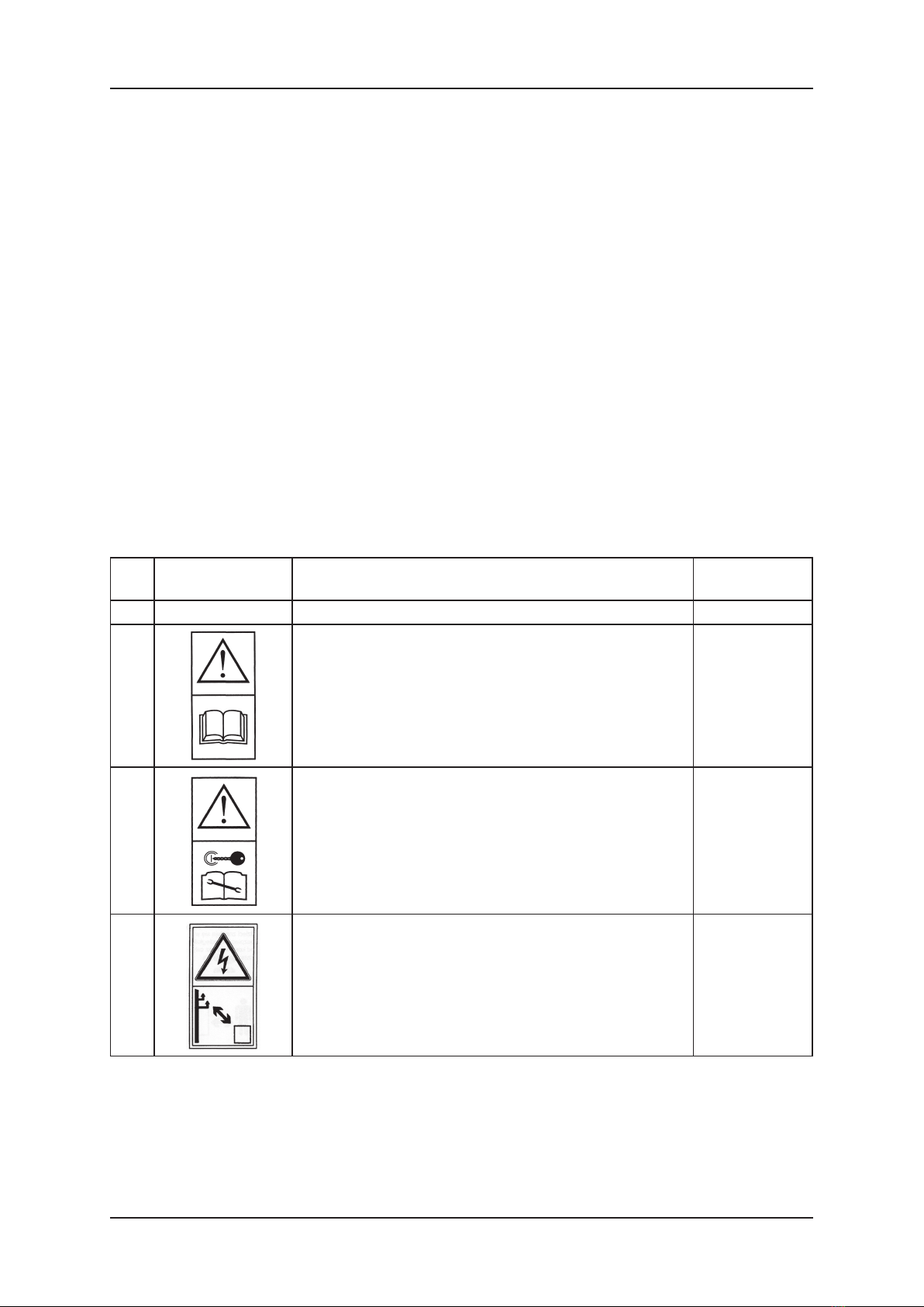
2.4. Warning signs and text on the trailer
The warning signs and text on the trailer must not be removed. They are intended for safe
handling of the trailer. If any information label is damaged or removed, order a spare one. Text
and symbol label stickers are available at service agents or at the trailer manufacturer.
Table 1
Item Safety symbol (sign) Meaning of the symbol (sign) or text Location on the
machine
12 3 4
1Read the operating instructions
On the load
body frame front
crosspiece
2Turn off the engine and remove the ignition key before
servicing or repairs
On the load body
front crosspiece
3 Keep a safe distance from power lines On the load body
front crosspiece
Operating instructions. T735 farming trailer 13
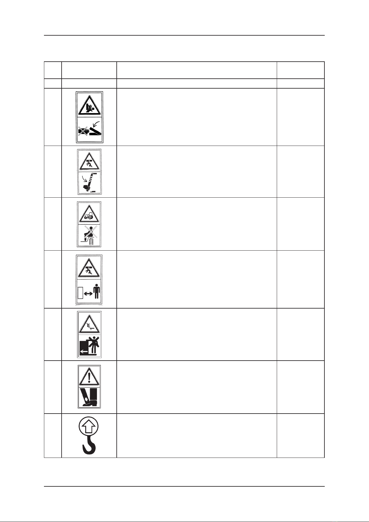
Item Safety symbol (sign) Meaning of the symbol (sign) or text Location on the
machine
12 3 4
4 Do not reach into the crushing area if the parts may move On side walls/
panels
5 Install the support before entering the hazardous area
On the chassis
side frame
member, at the
support
6Do not ride on the machine – use the passenger seat only On the load body
front wall
7 Keep a safe distance from the machine On the load body
front wall
8Do not stand on ladders and platforms while the tractor is
moving At the ladder
9Feet (toes) crushing hazard.
Force applied from above At the support
10 Lifting point
On the chassis
frame side
members
Table 1, continued

Operating instructions. T735 farming trailer 14
Item Safety symbol (sign) Meaning of the symbol (sign) or text Location on the
machine
12 3 4
11 Warning text on the
trailer
"Couple with the tractor upper hitch only that is rated for 11.5
kN of load"
On the load body
front wall
12
11.5 kN max On the tow bar
Caution!
Do not perform any checks or servicing under the loaded or
tilted load body without the support
At the support
Caution!
Do not remain within the range of discharged loads
Do not enter the trailer when it is hauled
On the load body
front wall
13 "Load capacity 2.5 t" On the load body
left and right wall
14 Maximum hydraulic system pressure: 16 MPa
On the oor
frame front
crosspiece
15
Maximum pneumatic system pressure
- 0.6 MPa, single-line system
- 0.8 MPa, two-line system
On the load body
front wall
16 Approximate weight values of certain goods –
acc. to section 5.3 on p. 19
On the load body
front wall
17 Tyre pressure
- "400 kPa" - 10.0/75-15.3 10PR tyres (MITAS)
- "475 kPa" - 10.0/75-15.3 12PR tyres (MITAS)
- "520 kPa" - 10.0/75-15.3 10PR tyres (BKT)
- "640 kPa" - 10.0/75-15.3 12PR tyres (BKT)
Over the wheels
INFORMATION! The trailer user is required to keep the warning symbols and text on the trailer
legible during its entire operating life. If damaged or destroyed, replace with new
ones.
3. TECHNICAL CHARACTERISTICS
T735 trailer Table 2
Item Contents
I General data
1. Vehicle type - farming truck trailer
2. Manufacturer - METAL-FACH Sp. z o.o.
16-100 Sokółka, ul. Kresowa 62
3. Type (model) - T735
4. Body type - box type, tipper
5. Nameplate location - load body frame front crosspiece
6. S/N stamping location - on the nameplate and underneath
II Dimensions and weight
7. Length, mm 4300
8. Width, mm 1895
9. Height, mm 1315
Table 1, continued

Operating instructions. T735 farming trailer 15
10. Number of axles, pcs. 1 (singe axle)
11. Wheel track, mm 1400
12. Front overhang, mm 3295
13. Rear overhang, mm 1005
14. Loading room size
- length, mm 2900
- width, mm 1730
- height, mm 500
- load surface, m25
- capacity, m32.5
15. Loading surface height, mm 815
16. Tow bar hitch-ring height, mm 290-490
17. Tow bar hitch-ring diameter, mm 40
18. Vehicle ramp clearance, mm 340
19. Vehicle kerb weight, kg 900
20. Permissible vehicle overall weight, kg: 3400
- per axle, kg 2462
- on the hitch, kg 938
21. Maximum axle load, kN
- per axle, kN 24.16
- on the tow bar hitch-ring (hitch), kN 9.2
22. Permissible vehicle load capacity, kg 2500
IV Suspension
23. Suspension type rigid, dependent, w/o suspension springs
V Wheels and tyres
24. Number of wheels, pcs. 2
25. Wheel disk size 9.00x15.5
26. Tyre size and PR number 10.0/75-15.5 14PR
- PR number 10 12 10 12
- tyre manufacturer MITAS MITAS BKT BKT
27. Tyre pressure, kPa 400 475 520 640
VI Braking system
28. Service brake;
- type mechanical, drum-type
- control pneumatic, positive pressure, two-line brake system;
(single-line system available on request)
- no. of wheels operated 2 wheels
29. Parking brake
- type mechanical, drum-type
- control manual, by a screw gear
- operated components 2 wheels on the axle
VII Electrical system
30. Voltage rating, V12, feed by the driving tractor
VIII Unloading mechanism
31. Mechanism type hydraulic
32. No. of actuators/members, pcs./pcs. 1 / 3
33. Maximum load body tilt angle, sideways/
back, by
45
34. Maximum system pressure, MPa 16
35. Hydraulic connection type ZSR-6-13/200 or acc. to PN-ISO 5675

Operating instructions. T735 farming trailer 16
IX Operating data
36. Minimum U-turn diameter, left/right, mm 5160
37. Maximum speed, km/h 40
X Additional information
38. Other information:
- tractor hitch coupling upper or lower transport hitch
- driving tractor 25 kW minimum
- requirements for the driving tractor minimum load transferred by the hitch: 11.5 kN
4. GENERAL DESCRIPTION OF DESIGN AND FUNCTION
The T735 trailer is a steel structure with the load body tipped to the sides and to the rear.
The trailer features a pneumatic service brake (with variable load braking force control) and a
parking brake that is hand-operated via a screw gear, actuating the friction components of the
axle service brake. The trailer features a complete signalling and warning system (an electrical
system and reective lights). The trailer is also suitable for transport on public roads.
The trailer is manufactured in accordance with Directive 98/37/EC and the following
harmonised standards: PN-EN 1853:2002, PN-EN ISO 4254-1:2006, PN-EN ISO 12100-
1:2005, PN-EN ISO 12100-2:2005, PN-EN 294:1994.
4.1. Chassis
The trailer chassis is composed of the following subassemblies: bottom frame, tow bar,
support foot, wheel set and fastening components.
The bottom frame and the tow bar are welded structures made of steel sheet and proles.
The trailer wheel set is composed of: a single axle, land wheels and land wheel brakes.
The axle is made of a square bar terminated with plugs on which land wheel hubs are set
by cone bearings. They are single wheels equipped with drum brakes with the jaws actuated by
mechanical expander cams.
4.2. Load body
The loading space of the trailer is made of the following:
The top frame (box frame) that is set on the bottom frame (chassis frame) in articulated seats
which serve as pivots during tilting (tipping) of the top frame (load body/box).
The side walls/boards and their top sections are singular components.
Operating instructions. T735 farming trailer 17
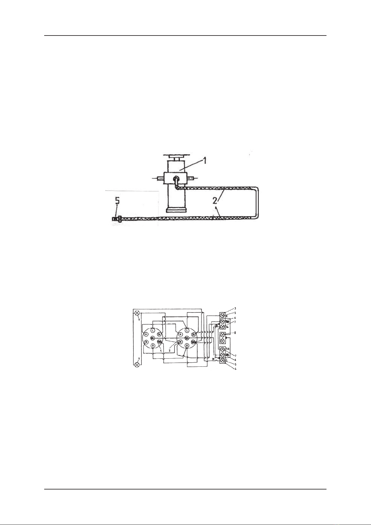
4.3. Load body hydraulic tipping mechanism
The hydraulic mechanism is designed for automatic unloading of the trailer by tipping the
load body backwards. The hydraulic tipping system is fed with oil from the tractor hydraulic
system.
The hydraulic system includes: the coupling valve plug, hydraulic lines, the single-action
hydraulic actuator, and connecting and fastening components. Figure 1 shows the diagram of
the load body hydraulic tipping system. The lifting and lowering of the load body is controlled
by the DCV in the tractor hydraulic system.
INFORMATION! * The cut-off valve limits the load body tilt angle during tipping to the sides. The
valve is pre-adjusted by the trailer manufacturer. Do not adjust it on your own.
Fig. 1 Diagram of the load body hydraulic tipping system
1 – hydraulic actuator; 2 – hydraulic lines; 3 – cut-off valve; 4 – cut-off valve control cable; 5 – coupling valve plug.
4.4. Electrical system (signalling and warning)
The trailer electrical system is designed for 12 V DC supply from the driving tractor system.
Connect the trailer electrical system with the tractor system by an appropriate coupling
cable. The diagram of the electrical system and the trailer lights layout is shown in g. 2 and 3.
Fig. 2 Trailer electrical system diagram
1 – 7-pin plug; 2 – 7-pin socket; 3 – right tail cluster lamp; 4 – left tail cluster lamp; 5 – turn indicator light bulbs; 6 – tail parking light bulbs;
7 – STOP light bulbs; 8 – registration plate light bulbs; 9 – front parking light bulb.
Operating instructions. T735 farming trailer 18
Fig. 3 Diagram of trailer lights layout
1 – cable harness with plug; 2 – right wire harness; 3 – front wire harness; 4 – rear wire harness; 5 – front parking lamp;
6 – front reector (white); 7 – tail reector (red); 8 – right tail cluster lamp; 9 – left tail cluster lamp; 10 – registration plate lamps;
11 – side reector (yellow).
4.5. Support foot
The T735 trailer is equipped with a mechanically operated support foot. It is designed to
support the tow bar when the trailer is decoupled from the tractor. The foot is installed at the
tow bar beam fork.
CAUTION! Do not rest the trailer on the support foot when it is loaded.
4.6. Braking system
The T735 trailer is equipped with the following braking systems:
• Service brake: pneumatically actuated two-line system, operates the axle wheels; controlled
from the driver's seat by pressing the tractor's brake lever;
• Parking brake: hand mechanical control via a crank lever mechanism and a screw gear,
located on the right side of the trailer and operating the axle wheels.
• The service brake design ensures automatic braking of all trailer land wheels if the pneumatic
system is accidentally decoupled between the trailer and the tractor. On customer's request,
the trailer can be alternately equipped with a single-line braking system (i.e. for adaptation
to tractors which support such system conguration).
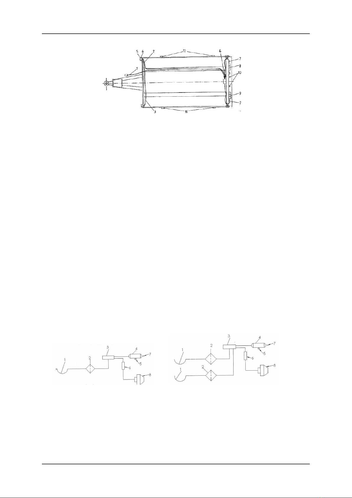
Figure 4 shows the pneumatic braking system diagram:
a) single-line system; b) two-line system.
Fig. 4 Pneumatic braking system diagram
1 – pneumatic connector plug for coupling with the tractor; 2 – air lter; 3 – control valve; 4 – air tank; 5 – water drain valve;
6 – manual braking force control; 7 – check connector; 8 – pneumatic membrane actuator.

Operating instructions. T735 farming trailer 19
5. STORAGE, SALE AND SHIPPING TO USER
STORAGE
• Protect the trailer from direct exposure to sunlight and rain. Park it with its land wheels and
with the supports extended and locked (if the tyres can be exposed to sunlight, reduce their
pressure).
• If the trailer is stored outdoors, periodically check for rainwater accumulation in the trailer.
Note all damage to the paint coat. Clean and degrease spots of damaged paint. Next, repaint
with the same colour and coat thickness.
• Long-term storage is allowed in sheltered rooms only.
SALE
• The buyer picks the trailer from the manufacturer or the sales representative on their own,
or arranges for the shipping with the manufacturer.
• The trailer is sold as fully assembled and ready for operation, complete with the basic
equipment listed in section 1.2 of this manual. All optional accessories or their parts are
available at extra charge.
• The sales representative personnel is required to introduce the buyer to the design and
operation of the trailer, along with safety requirements and warranty conditions.
• The buyer shall verify the following:
- the trailer is complete, undamaged and with all basic equipment;
- the nameplate located on the load body front frame crosspiece and the surface under it
has the serial number stamped that matches the data in the warranty card;
- the warranty card has been properly lled out with the identication data on the
nameplate.
SHIPPING TO USER
The trailer shall be transported from the sales representative on wheels as coupled with a
tractor or on a low-bed trailer. Before loading on a low-bed trailer, connect the farming trailer
with the transport hitch and the braking lines of the tractor. Drive the farming trailer to the low-
bed trailer with the extended ramps. Next, secure the farm trailer with wheel chocks. Afterwards,
disconnect the braking system and decouple from the tractor. Secure the farming trailer with
special transport straps. Before unloading the trailer, rst extend the low-bed trailer ramps
and release the transport straps used to secure the farming trailer from falling down in transit.
Approach with a tractor and connect the trailer braking system. Next, remove the wheel chocks
from the trailer. When all of the above has been completed, drive the trailer from the low-bed.

Operating instructions. T735 farming trailer 20
6. OPERATION INFORMATION
6.1. Commissioning the trailer
IMPORTANT! *Use only tractors that are t for service (with the transport hitch, the pneumatic
and hydraulic systems, and the signalling/warning system working)
Do the following before commissioning the trailer:
- Understand the names and locations of individual assemblies/components of the trailer
- check the tyre pressure
- couple the trailer with the tractor:
* set the tow bar hitch-ring of the trailer at the trailer transport hitch height;
* couple the hitch-ring with the trailer hitch;
* secure the hitch pin from falling out;
* turn off the tractor engine;
* engage the tractor parking brake;
* release the trailer parking brake;
* connect the appropriate sockets and plugs of the following systems: pneumatic, hydraulic
and electrical;
- do the functional checks of the electrical, pneumatic and hydraulic systems of the tractor
and of the trailer, and check leak tightness of the hydraulic and pneumatic systems on both
vehicles;
- check all equipment, their connections and safety from accidental release or breaking.
Do all these actions each time you start the trailer.
INFORMATION! Couple the trailer with the tractor transport hitch only that is rated for 11.5 kN
of minimum load. No bystanders shall remain between the trailer and the tractor
when the two are being coupled.
INFORMATION! Two persons and extreme caution are required to install and remove the top
sections.
6.2. Loading the body
Load the body only when the trailer is coupled with the tractor, parked on level ground and
with the tow bar in the forward driving direction.
Use mechanical loading equipment (cranes, loaders, conveyors, etc.) to load the trailer.
Make sure that all wall and top section locks are engaged before loading the trailer.
Spread the load evenly across the entire load body surface. If materials are to be transported
that exert focused (topical) pressure on the load body (e.g. large rocks), line the oor with thick
planks rst. This will reduce the surface load of the oor and protect it from damage.
If bulk loads are to be transported, install the top sections of the load body walls. If the
transported materials protrude beyond the trailer outline, follow the applicable trafc code
regulations to properly mark the protruding load.
INFORMATION! • Do not exceed the permissible payload and permissible axle loads, otherwise
the trailer can be damaged and the trafc safety compromised.
• The transported load must be secured against shifting, generating excessive
noise and falling down on the road.
Table of contents
Other Metal-Fach Utility Vehicle manuals


Popular Utility Vehicle manuals by other brands


McConnel
McConnel Multidrive M380-4 Operator's instruction manual

Taylor-Dunn
Taylor-Dunn B0-015-00 Operation, t roubleshooting and replacement parts manual

Kellfri
Kellfri 28 VBS+ manual

HAUL MASTER
HAUL MASTER 37510 parts list

MULTIQUIP
MULTIQUIP Whiteman WBH16 manual

Labrie
Labrie AUTOMIZER FULL EJECT Maintenance manual