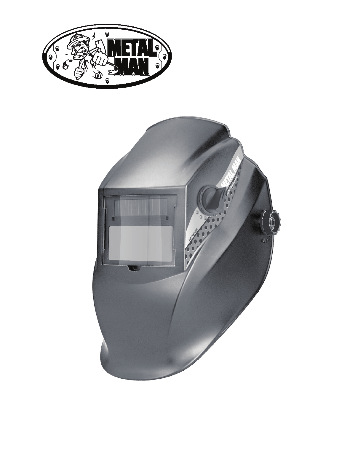
3
‘W’
‘Y’
‘Z’‘Z’ ‘T’‘T’ fig.1
TOP
fig.3
GRIND 9
10
11
12
13
• Test the fit of the headband by lifting up and closing down the
helmet a few times while wearing it. If the headband moves
while tilting, re-adjust it until it is stable.
• ADJUSTING THE DISTANCE BETWEEN THE HELMET
AND THE FACE
Step 1: Undo the block nut (See “T” in fig.1) to adjust the
distance between the helmet and your face in the down
position.
Step 2: Loosen the block nut on either side of the helmet and
slide it nearer or further from your face. (See adjustment “Z” in
fig.1). It is important that your eyes are each the same distance
from the lens. Otherwise the darkening effect may appear
uneven.
Step 3: Re-tighten the block nut when adjustment is complete.
• ADJUSTING VIEW ANGLE POSITION
Please see fig.2.
• SELECTING SHADE LEVEL
Select the shade level you require according to the welding
process you will use by referring to the “Shade Guide Table”
below for settings. Turn the shade control knob on the side of
the helmet to the shade number required.
• SELECTING THE GRIND OPTION
When the shade knob is turned to the “Grind” position, the
shade function is turned off allowing a clear view to grind a
weld with the helmet providing face protection. Before restarting
welding work, Ensure that the shade function is turned back on
before welding again (See fig.3).
• You are now ready to use the helmet. The shading may be adjusted during use by
re-setting the potentiometer control.
fig.2
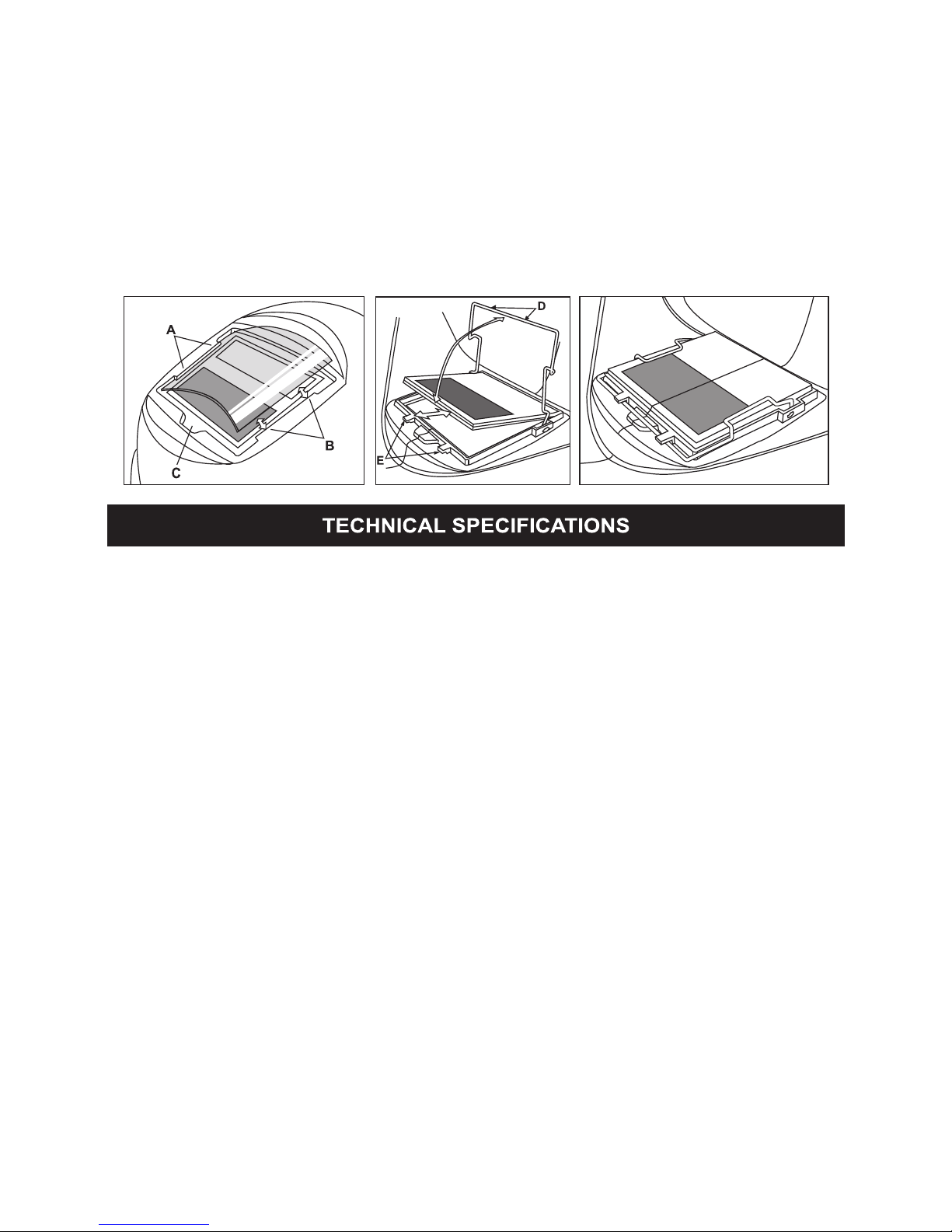
• REPLACE THE FRONT COVER LENS. Replace the front cover lens if it is damaged
(cracked, scratched, dirty or pitted) Place your finger or thumb into the recess at the bottom
edge of the wirdow and flex the window upwards until it releases from one edge (See fig.4).
• REPLACE THE INNER COVER LENS. If it is damaged (cracked, scratched, dirty or pitted).
• CHANGING THE SHADE CARTRIDGE (See figs.5a & 5b).
• INSTALLING NEW CARTRIDGE. Take the new shade cartridge and pass the potentiometer
cable under the wire loop before dropping the cartridge into its retaining frame inside the
helmet. Press down the wire loop clip and ensure that the front edge of the loop is properly
retained under the retaining lugs as shown in fig.5b.
• Fasten the potentiometer to the inside of the helmet with the shaft protruding through the
hole. Push the shade control knob onto the shaft.
• CLEANING. Clean helmet by wiping with a soft cloth. Clean cartridge surfaces regularly.
Do not use strong cleaning solutions. Clean sensors and solar cells with methylated spirit
and a clean cloth and wipe dry with a lint-free cloth.