METAL PLESS MAXXPRO User manual

Owner’s Manual
© All rights reserved 2021
MAXXPRO
The width of the blade does not determine the real dimension of the product. Pictures shown might have some options.
V1
SCAN ME
with your camera
application
on any phone
TECHNICAL
SHEET
MADE IN
CANADA
READING THIS MANUAL IS MANDATORY BEFORE
OPERATING THIS EQUIPMENT
IMPORTANT
THIS EQUIPMENT MAY BE SUBJECT TO
DIFFERENT LAWS IN SOME PROVINCES, STATES OR COUNTRIES.
THE USER MUST KNOW LAWS AND RULES
GOVERNING TRANSPORTATION
AND
USE OF THIS EQUIPMENT ON PUBLIC ROADS.
OWNERSHIP OF THIS EQUIPMENT DOES NOT
CREATE SKILLS, OR ABILITIES TO OPERATE THIS EQUIPMENT.
SOME PARTS AND / OR COMPONENTS
OF THIS EQUIPMENT ARE PROTECTED UNDER PATENT
AND CANNOT BE COPIED AND / OR REPLICATED.
WARNING
CONSTANT ATTENTION MUST BE GIVEN WHEN USING THIS EQUIPMENT.
THIS EQUIPMENT CANNOT BE LEFT UNATTENDED WHILE IN OPERATION.
NEVER POSITION BETWEEN THIS EQUIPMENT AND THE GROUND
IF THIS EQUIPMENT HAS NOT BEEN PREVIOUSLY
LIFTED AND SECURE BY MEANS OF TOOLS
BREEDING AND SUPPORT APPROVED FOR THIS TASK.
MISUSE OF THIS EQUIPMENT MAY CAUSE DAMAGE AND SERIOUS RISK.
COMPONENTS MUST BE VERIFIED BEFORE USING THIS EQUIPMENT.

Contents
1. TECHNICAL SHEET . . . . . . . . . . . . . . . . . . . . . . . . . . . . . . . . . . . . . . . . . . . . . . . . . . . . . . . . . . . . . 1
1.1 DESCRIPTION . . . . . . . . . . . . . . . . . . . . . . . . . . . . . . . . . . . . . . . . . . . . . . . . . . . . . . . . . . . . . . . . . . . . .1
1.2 OPTIONAL EDGES . . . . . . . . . . . . . . . . . . . . . . . . . . . . . . . . . . . . . . . . . . . . . . . . . . . . . . . . . . . . . . . . . .2
2. INTRODUCTION . . . . . . . . . . . . . . . . . . . . . . . . . . . . . . . . . . . . . . . . . . . . . . . . . . . . . . . . . . . . . . . . 3
2.1 NO MODIFICATION . . . . . . . . . . . . . . . . . . . . . . . . . . . . . . . . . . . . . . . . . . . . . . . . . . . . . . . . . . . . . . . . .3
2.2 USAGE . . . . . . . . . . . . . . . . . . . . . . . . . . . . . . . . . . . . . . . . . . . . . . . . . . . . . . . . . . . . . . . . . . . . . . . . . . .3
2.3 MAINTENANCE . . . . . . . . . . . . . . . . . . . . . . . . . . . . . . . . . . . . . . . . . . . . . . . . . . . . . . . . . . . . . . . . . . . .3
2.4 USER’S MANUAL . . . . . . . . . . . . . . . . . . . . . . . . . . . . . . . . . . . . . . . . . . . . . . . . . . . . . . . . . . . . . . . . . .3
2.5 AUTHORIZED OPERATOR . . . . . . . . . . . . . . . . . . . . . . . . . . . . . . . . . . . . . . . . . . . . . . . . . . . . . . . . . . . .3
2.6 LIMITED WARRANTY . . . . . . . . . . . . . . . . . . . . . . . . . . . . . . . . . . . . . . . . . . . . . . . . . . . . . . . . . . . . . . .3
3. WARRANTY POLICY . . . . . . . . . . . . . . . . . . . . . . . . . . . . . . . . . . . . . . . . . . . . . . . . . . . . . . . . . . . . . 4
4. USAGE OF THE EQUIPMENT & COMPONENTS . . . . . . . . . . . . . . . . . . . . . . . . . . . . . . . . . . . . . . . 5
5. EQUIPMENT IDENTIFICATION . . . . . . . . . . . . . . . . . . . . . . . . . . . . . . . . . . . . . . . . . . . . . . . . . . . . 6
6. INITIAL ASSEMBLY . . . . . . . . . . . . . . . . . . . . . . . . . . . . . . . . . . . . . . . . . . . . . . . . . . . . . . . . . . . . . 7
6.1 HYDRAULIC HOSES . . . . . . . . . . . . . . . . . . . . . . . . . . . . . . . . . . . . . . . . . . . . . . . . . . . . . . . . . . . . . . . .7
6.2 HYDRAULIC COMPONENTS . . . . . . . . . . . . . . . . . . . . . . . . . . . . . . . . . . . . . . . . . . . . . . . . . . . . . . . . . .8
6.3 QUICK COUPLER INSTALLATION . . . . . . . . . . . . . . . . . . . . . . . . . . . . . . . . . . . . . . . . . . . . . . . . . . . . .8
7. SAFETY . . . . . . . . . . . . . . . . . . . . . . . . . . . . . . . . . . . . . . . . . . . . . . . . . . . . . . . . . . . . . . . . . . . . . . 10
7.1 UNDERSTANDING LABELS AND INSTRUCTIONS . . . . . . . . . . . . . . . . . . . . . . . . . . . . . . . . . . . . . . .10
7.2 SAFETY PERIMETER . . . . . . . . . . . . . . . . . . . . . . . . . . . . . . . . . . . . . . . . . . . . . . . . . . . . . . . . . . . . . . .10
7.3 SAFETY DISPLAY (STICKERS) . . . . . . . . . . . . . . . . . . . . . . . . . . . . . . . . . . . . . . . . . . . . . . . . . . . . . . .12
8. FUNCTIONS AND OPERATIONS . . . . . . . . . . . . . . . . . . . . . . . . . . . . . . . . . . . . . . . . . . . . . . . . . . 13
8.1 LEVELLING THE PLOW . . . . . . . . . . . . . . . . . . . . . . . . . . . . . . . . . . . . . . . . . . . . . . . . . . . . . . . . . . . . .13
8.2 HYDRAULIC WINGS . . . . . . . . . . . . . . . . . . . . . . . . . . . . . . . . . . . . . . . . . . . . . . . . . . . . . . . . . . . . . . .14
8.3 COIL SPRINGS . . . . . . . . . . . . . . . . . . . . . . . . . . . . . . . . . . . . . . . . . . . . . . . . . . . . . . . . . . . . . . . . . . . .15
8.4 VISUAL MARKERS . . . . . . . . . . . . . . . . . . . . . . . . . . . . . . . . . . . . . . . . . . . . . . . . . . . . . . . . . . . . . . . . .16
8.5 VISUAL MARKERS WITH LEVELING INDICATORS . . . . . . . . . . . . . . . . . . . . . . . . . . . . . . . . . . . . . .16
8.6 CUTTING EDGES (WEAR) . . . . . . . . . . . . . . . . . . . . . . . . . . . . . . . . . . . . . . . . . . . . . . . . . . . . . . . . . . .16
8.7 CUTTING EDGES (REPLACEMENT) . . . . . . . . . . . . . . . . . . . . . . . . . . . . . . . . . . . . . . . . . . . . . . . . . . .17
8.8 HYDRAULIC CYLINDERS . . . . . . . . . . . . . . . . . . . . . . . . . . . . . . . . . . . . . . . . . . . . . . . . . . . . . . . . . . .18
8.9 FIFTH WHEEL . . . . . . . . . . . . . . . . . . . . . . . . . . . . . . . . . . . . . . . . . . . . . . . . . . . . . . . . . . . . . . . . . . . .18
9. MAINTENANCE . . . . . . . . . . . . . . . . . . . . . . . . . . . . . . . . . . . . . . . . . . . . . . . . . . . . . . . . . . . . . . . . 19
9.1 PRIOR NOTICE . . . . . . . . . . . . . . . . . . . . . . . . . . . . . . . . . . . . . . . . . . . . . . . . . . . . . . . . . . . . . . . . . . . .19
9.2 DAILY INSPECTION . . . . . . . . . . . . . . . . . . . . . . . . . . . . . . . . . . . . . . . . . . . . . . . . . . . . . . . . . . . . . . . .19
9.3 GREASING . . . . . . . . . . . . . . . . . . . . . . . . . . . . . . . . . . . . . . . . . . . . . . . . . . . . . . . . . . . . . . . . . . . . . . .19
9.4 GREASE TYPE . . . . . . . . . . . . . . . . . . . . . . . . . . . . . . . . . . . . . . . . . . . . . . . . . . . . . . . . . . . . . . . . . . . .19
9.5 LUBRIFICATION POINTS . . . . . . . . . . . . . . . . . . . . . . . . . . . . . . . . . . . . . . . . . . . . . . . . . . . . . . . . . . .20
Owner’s Manual
1
The width of the blade does not determine the real dimension of the product. Pictures shown might have some options.
MAXXPRO
1.1 DESCRIPTION
1. TECHNICAL SHEET
BOX
HEIGHT EXTENDED
HD LE
PRO 0848-18 8' 48" 18' 25 000 lbs and up 4 700 lbs PRO 0848-18 28 895$ 33 495$
PRO 0848-20 8' 48" 20' 25 000 lbs and up 4 900 lbs PRO 0848-20 29 995$ 34 995$
PRO 1048-18 10' 48" 18' 25 000 lbs and up 4 800 lbs PRO 1048-18 28 995$ 34 145$
PRO 1048-20 10' 48" 20' 25 000 lbs and up 5 000 lbs PRO 1048-20 30 355$ 35 645$
PRO 1048-22 10' 48" 22' 25 000 lbs and up 5 200 lbs PRO 1048-22 31 995$ 37 995$
PRO 1048-26 10' 48" 26' (van) 25 000 lbs and up 5 900 lbs PRO 1048-26 37 595$ 43 995$
PRO 1248-20 12' 48" 20' 30 000 lbs and up 5 200 lbs PRO 1248-20 31 325$ 36 995$
PRO 1248-22 12' 48" 22' 30 000 lbs and up 5 400 lbs PRO 1248-22 32 445$ 38 355$
PRO 1248-24 12' 48" 24' 30 000 lbs and up 5 600 lbs PRO 1248-28 34 225$ 40 565$
PRO 1248-28 12' 48" 28' (van) 30 000 lbs and up 6 300 lbs PRO 1248-25 39 995$ 46 995$
PRO 1448-25 14' 48" 25' 35 000 lbs and up 6 400 lbs PRO 1448-25 41 695$ 48 995$
PRO 1648-30 16' 48" 30' 40 000 lbs and up 7 000 lbs PRO 1648-30 48 995$ 57 225$
PRO 2048-36 20' 48" 36' 50 000 lbs and up 10 000 lbs PRO 2048-36 77 995$ 87 995$
PRO 2460-44 24' 60" 44' 60 000 lbs and up 15 000 lbs PRO 2460-44 89 675$ 101 755$
PRO 3260-60 32' 60" 60' 70 000 lbs and up 18 000 lbs PRO 3260-60 107 995$ 134 995$
FERMÉE HAUTEUR
OUVERTE HD LE
PRO 0848-18 8' 48" 18' 25 000 lbs et plus 4 700 lbs PRO0848-18 28 895 $ 33 495 $
PRO 0848-20 8' 48" 20' 25 000 lbs et plus 4 900 lbs PRO0848-20 29 995 $ 34 995 $
PRO 1048-18 10' 48" 18' 25 000 lbs et plus 4 800 lbs PRO1048-18 28 995 $ 34 145 $
PRO 1048-20 10' 48" 20' 25 000 lbs et plus 5 000 lbs PRO1048-20 30 355 $ 35 645 $
PRO 1048-22 10' 48" 22' 25 000 lbs et plus 5 200 lbs PRO1048-22 31 995 $ 37 995 $
PRO 1048-26 10' 48" 26' (van) 25 000 lbs et plus 5 900 lbs PRO1048-26 37 595 $ 43 995 $
PRO 1248-20 12' 48" 20' 30 000 lbs et plus 5 200 lbs PRO1248-20 31 325 $ 36 995 $
PRO 1248-22 12' 48" 22' 30 000 lbs et plus 5 400 lbs PRO1248-22 32 445 $ 38 355 $
PRO 1248-24 12' 48" 24' 30 000 lbs et plus 5 600 lbs PRO1248-28 34 225 $ 40 565 $
PRO 1248-28 12' 48" 28' (van) 30 000 lbs et plus 6 300 lbs PRO1248-25 39 995 $ 46 995 $
PRO 1448-25 14' 48" 25' 35 000 lbs et plus 6 400 lbs PRO1448-25 41 695 $ 48 995 $
PRO 1648-30 16' 48" 30' 40 000 lbs et plus 7 000 lbs PRO1648-30 48 995 $ 57 225 $
PRO 2048-36 20' 48" 36' 50 000 lbs et plus 10 000 lbs PRO2048-36 77 995 $ 87 995 $
PRO 2460-44 24' 60" 44' 60 000 lbs et plus 15 000 lbs PRO2460-44 89 675 $ 101 755 $
PRO 3260-60 32' 60" 60' 70 000 lbs et plus 18 000 lbs PRO3260-60 107 995 $ 134 995 $
APPR O X.
WEIGHT
RETAIL PRICE
MODEL
MODEL
BLADE DIMENSIONS
APPLICAT IO N
MODEL
DIMENSIONS DE LA LAM E
PO ID S
APPR O X.
MODÈLE
PRIX DE DÉTAIL
VÉHICULE
CO M PATIB LE
OPTIONS (not included)
Carbide cutting edge (CCE).
Non standard color (NSC1).
Electric valve and joystick (JSC3) 12 or
24 volts: electric over hydraulic 1 spools
mounted on blade with electric control
and necessary cable for the installation
in the tractor cab..
Power angle max. 102’’ (MA102)
Includes angular system and quick coupler for industrial loader.
This system requires 1 set of oil outlets.
Not included: hydraulic hoses and connectors from the blade to the vehicle.
Available in HD, LE or RB-LE
HD
SOFT DRIVE TRIP EDGE
BLADE POSITIONS
LE
LIVE EDGE
HD or LE
HD or LE
HD or LE
HD or LE
HD or LE
HD or LE
HD or LE
HD or LE
HD or LE
HD or LE
HD or LE
HD or LE
HD or LE
HD or LE
HD or LE
Prices, specs, models and/or model numbers are subject to change.
Industrial snow plow with hydraulic wings
and angle.The MaxxPro is installed
on a wheel loader.
MAXXPRO 2
1.2 OPTIONAL EDGES
LE - Floating cutting LIVE EDGE
A floating soft drive steel trip edge with carbide inserts for longer wear life, that
contours the unevenness of the ground for a cleaner result.
HD - Soft drive trip edge
Unique soft drive trip edge design allows the individual sections to trip
backwards without the blade being lifted upwards, greatly reducing the impact.
RB-LE - Rubber LIVE EDGE
Individual floating rubber edge contouring the unevenness of the ground for a
cleaner result while protecting delicate surfaces.
HD
SOFT DRIVE TRIP EDGE
RB-LE
RUBBER LIVE EDGE
LE
LIVE EDGE

Owner’s Manual
3
2. INTRODUCTION
The user must take note of the following information that may change the nature of the
agreement between the manufacturer and the owner of the equipment.
2.1 NO MODIFICATION
In no event shall this equipment be changed without the agreement of the
manufacturer. Defects caused by alterations or modifications of this equipment in its
nature or vocation, voids the warranty.
2.2 USAGE
Normal usage for this equipment includes wear or damages due to the operations
and regular use.
2.3 MAINTENANCE
Lack of reasonable and proper maintenance, non-compliance of the operating
instructions and / or the inability to manage the product according to the
specifications, misuse, lack of proper protection during storage, or accident, may
void the warranty.
2.4 USER’S MANUAL
This manual should follow this equipment at all times and is considered as one of
the components of this equipment.
2.5 AUTHORIZED OPERATOR
Only authorized and trained personnel may proceed with the operation of this
equipment, its maintenance and transportation.
2.6 LIMITED WARRANTY
This equipment comes with a limited one (1) year warranty available from the
manufacturer.

MAXXPRO 4
WARRANTY POLICY
on new METAL PLESS equipment.
METAL PLESS offers a warranty on all new equipment for a period of 1 year after date of retail
purchase.
AN APPROVAL FROM METAL PLESS IS REQUIRED BEFORE ANY REPAIRS OR WARRANTY
CLAIMS. PHOTOS AS WELL AS THE SERIAL NUMBER WILL BE REQUIRED.
Parts are F.O.B. Plessisville, QC.
All defective parts must be returned to METAL PLESS within a period of 30 days and follow our
mandatory procedures for returning parts.
The METAL PLESS warranty covers all defects in material or fabrication of the products only,
and therefore does not cover the normal wear or non-recommended utilization of the product.
Damage resulting from an accident or abusive use will not be covered by the warranty policy.
The warranty does not cover any traveling fees/expenses to access the equipment for evaluation
or repairs.
Only original parts or METAL PLESS approved parts will be considered appropriate for warranty
claims.
METAL PLESS reserves the right to refuse or modify any labor time deemed excessive for any
repair work claimed on warranty.
The paint standard for all replacement parts out of the factory will be standard Metal Pless color.
The warranty policy does not apply to the NORMAL WEAR PARTS. Examples listed below.
Examples: Cutting edges, Wear shoes, Abrasion shoes, Curb runners, Impact Guards, Tire
Savers, Couplers, Hydraulic Hoses, Coils, Solenoids, etc.
PURCHASER’S RESPONSIBILITIES
The present warranty presumes a correct maintenance and periodic inspections of the
equipment by the owner, as described in the Owner’s Manual provided with the equipment at
time of purchase. The cost of regular maintenance or required servicing is the responsibility of
the client.
The buyer must conserve all receipts proving that the required maintenance has been respected.
EXCLUSIONS ON SUBSEQUENT MANUFACTURER UPGRADES
METAL PLESS reserves the right to modify, change or improve any product with no obligation to
replace or modify any previously purchased equipment.
1.
2.
3.
4.
5.
6.
7.
8.
9.
1 819 362.2221
1 866 362.1688
1683, boulevard des Sucreries
Plessisville, Québec (CANADA), G6L 1W4
metalpless.com
info@metalpless.com
3. WARRANTY POLICY

Owner’s Manual
5
4. USAGE OF THE EQUIPMENT & COMPONENTS
PRESCRIBED USE (S)
This equipment must be connected to a motorized vehicle and used for outdoor snow
removal and to accomplish the following operations:
a) Push snow forward.
b) Backdrag snow.
c) Windrow snow left or right.
* Always wear a seat belt when operating a motor vehicle.
Any other non-prescribed use of this equipment will void any warranty or liability.
DURING OPERATION
a) Make sure that no one is in your area of operation, keeping a lookout for blind
spots.
b) Do not clear snow at excessively high speeds.
c) Avoid hitting any objects that could damage the equipment.
DURING INACTIVITY
* Before adjusting or repairing equipment, always apply the parking brakes, stop the
engine, and lower the equipment to the ground.
Always be cautious when leaving equipment unattended.
a) Lower the snow blade to the ground when parking your vehicle for extended
period of time.
b) Set all switches to the “OFF” position to prevent the snow plow from draining
power from the vehicle’s battery. The equipment may continue to draw current if the
control switch is turned to the“ON”position; possibly causing insufficient charge to
restart the vehicle.
Any breakage CAUSED BY excessive collision may not be covered under warranty
MAXXPRO 6
5. EQUIPMENT IDENTIFICATION
Find the identification of the equipment, behind the central part at the top left corner.
A permanent label shown in (Fig. 1) indicates the model number and
the serial number.
Fig.1
Model
Width of
mouldboard
Height
LIVE EDGE,
HD or RB-LE
# Production
Total width Year and month
of manufacturing
AGH1036 - 16LE - 1610 - 1234PRO 1048
Owner’s Manual
7
Fig.1
6. INITIAL ASSEMBLY
Upon initial receipt of the equipment, some assembly may be required, check the
following:
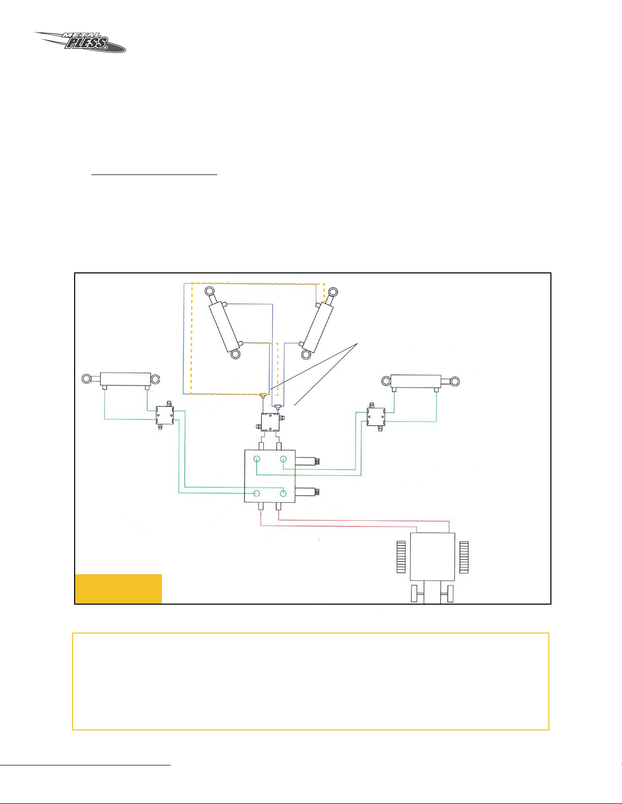
6.1 HYDRAULIC HOSES
The equipment may require additional hydraulic hoses from the vehicle to the snow
plow. It is the responsibility of the user to supply these. Hydraulic hoses must be
routed and positioned in a way that they do not bind with mobile parts of the equip-
ment. In certain conditions, it is recommended to add supports or protective sheath
to to keep the hydraulic hoses protected. (Fig.2)
Warning: Diverter valves are available in 12 or 24 volts. Verify the coils on the
valve to appropriately feed the correct voltage.
Warning: The fuse associated with the power source must not exceed 10 amps.
Vehicle
Relief valve
A1 (P1)
B1
C1
C1
C2
C2
B2
A2 (P2)
Relief valve
Relief valve
Fig.2
Hydraulic system
diagram
The initial installation is done by Metal
Pless. However, it is recommended to
confirm that the assembly of the hydraulic
system matches the diagram.
MAXXPRO 8
6.3 QUICK COUPLER INSTALLATION
In order to attach the plow to a loader, follow these procedures.
Using the loader’s quick coupler, approach the plow with caution and hook onto it.
Make sure the locking pins are activated.
6.2 HYDRAULIC COMPONENTS
a) It is strongly recommended that all hydraulic components (fittings, valves,
cylinders etc.) be verified before initial operation. It is the owner’s responsibility to make
sure that all components are secure, operational and free of leaks.
b) Hydraulic hoses will need to be provided and installed from the loader to the
diverter valve. Hoses arriving from the loader must enter port A1, A2 or P1, P2 of the
diverter valve. Depending on model of valve these ports may either be on the left or the
right side of the valve. (Fig.2)
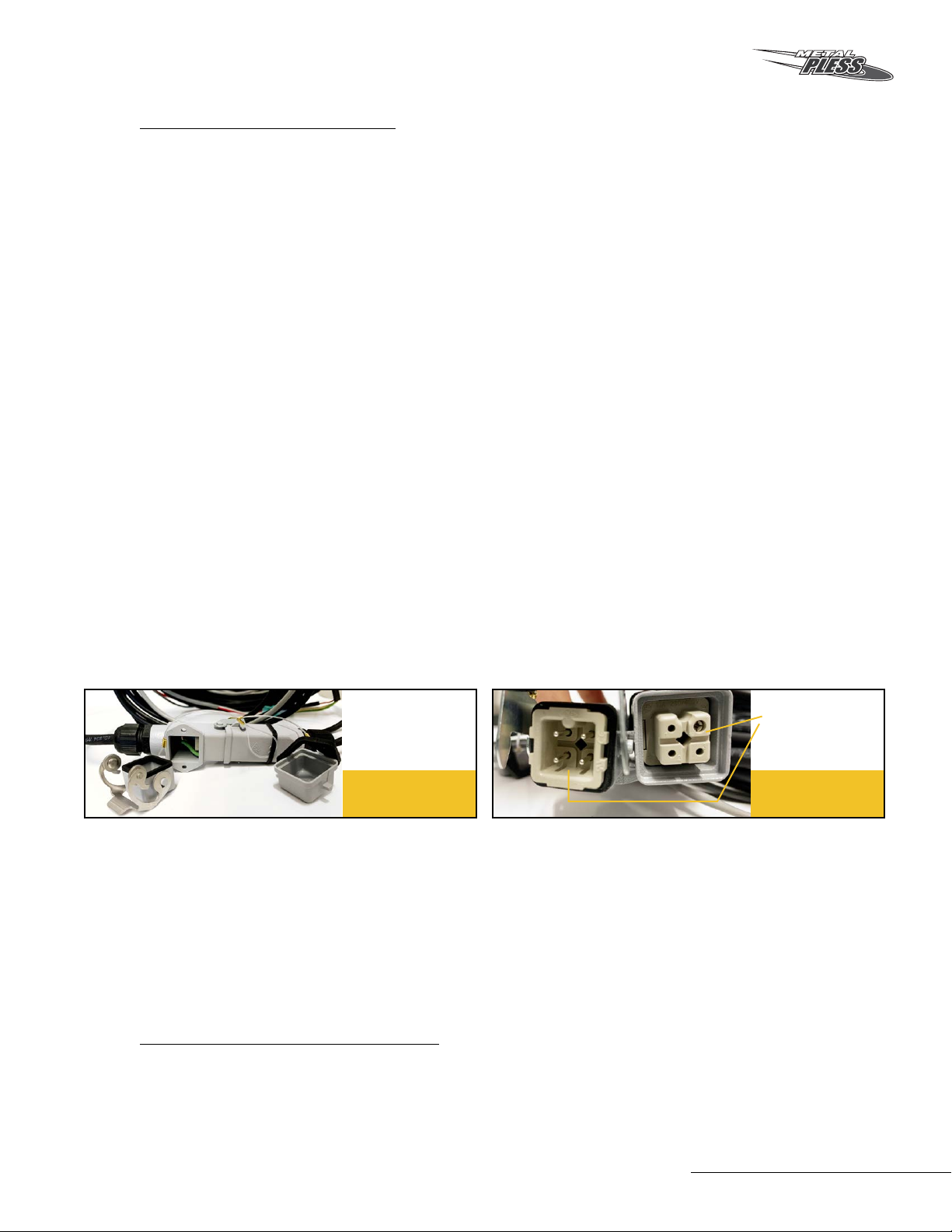
c) Attached to the diverter valve is a wiring harness. Run the wiring up the loader arms
and into the cab. Depending on model chosen, install the controller
accordingly. In the cab, it will be necessary to hook up the wiring into an available and
adequate power source.
d) Required power source (either 12 or 24 volts) will be dictated by the voltage of the
coils.
e) The wiring harness includes a male/female sealed connector (Fig.2.1). This connector
is useful when detaching the snow plow from the vehicle. It is strongly recommended to
add electrical grease on the connectors (Fig.2.2). It is also imperative that the operator
takes care to prevent moisture from entering the connector. Safety caps with molded
rubber seals are included and must be used properly when coupling and uncoupling the
blade to prevent possible failure of the wiring harness.
f) The hydraulic wings are equipped with flow control valves. Is is important that these
valves are adjusted correctly to allow a smooth rotation of the wings.
g) Relief valves (Fig.2) are installed for protection of the hydraulic cylinders. These are
pre-set at the factory. It is not recommended to adjust these without prior approval from
Metal Pless. If adjustment is necessary, note that both ports of the relief valve must be
adjusted simultaneously for proper pressure relief of oil flow in either direction.
Fig.2.1 Fig.2.2
Male/female
connector
Add electrical
grease

Owner’s Manual
9
-
Recommended settings
for hydraulic pressure (PSI)
and flow (GPM)
-MAXIMUM PSI SHOULD BE 3000 PSI -
13 mum
24 GPM mimum
MAKE SURE VOU RESPECT OUR
TWO STEP WARRANTY
CONDITIONS.
Jimmy VIGNEAULT
President, Métal Pless
metalpless.com O
0 CONFIRM YOUR TYPE OF VALVE
ADJUST THE HYDRAULIC LIMITERS
#1 snow plow in the world

MAXXPRO 10
7. SAFETY
7.1 UNDERSTANDING SAFETY DISPLAYS AND INSTRUCTIONS
All users should consider safety displays in order to understand the risks associated
with equipment operations and functions such as:
a) A dangerous situation that could result in injury to the user.
b) A dangerous situation that can cause damage to the equipment.
c) A dangerous situation that could lead to hazards within the perimeter of the
equipment.
d) A dangerous situation that could result in the manipulation of components contai-
ning fluids under high pressure.
e) The user must consider the hazards associated with the use of mobile equipment.
Associated risks are multiple and real.
7.2 SAFETY PERIMETER
During inactivity, the user must ensure a safe distance between the equipment, the
vehicle to which it is harnessed and other dangerous equipment or dangerous
situations.
The usage of this equipment on another motorized equipment changes the behavior,
conduct and balance; requiring professional expertise recognition.
During the operation of this equipment, the user must maintain a safe distance
between the equipment and it’s environment. The higher the speed, the higher the
risks.
(See point 7.3)

Owner’s Manual
11
SNOW EJECTS AT GREAT SPEED AND DISTANCES, AND CAN
CREATE HARMFUL IMPACTS.
DURING OPERATION, THIS EQUIPMENT CAN CAUSE THE
VEHICLE TO BECOME UNBALANCED AND CAUSE A LOSS OF
CONTROL.
The user should consider that the use of this equipment reduces its overall vision
and that the operator must therefore be vigilant. In addition, the user must act
responsibly for vehicles in his/her surrounding, making safety a priority at all times.
Make sure to respect your country’s state and provincial laws in force regarding the
signaling and reflective strips to be present on this equipment.
WARNING
MAXXPRO 12
7.3 SAFETY DISPLAY (STICKERS)
It is important for the user to identify these safety displays on the snow plow before
operating or servicing the equipment.
MTP-0017
LUBRIFICATION POINT - POINT DE LUBRIFICATION
MADE IN CANADA
FAIT AU CANADA
Recto Verso: Recto seulement
Bleed: Non
Endos pré-coupé:
Oui
L. x H.
Tél.:
1 819 362-2221 241
Fax:
À:
Rouge PMS 186C, Noir
Vinyle blanc mat 0,004"
Aucun
Dimensions:
De:
Mario Cardinal M.V. #13
Coins:
R. 1/4"
E-mail:
Projet:
Autocollant "DANGER BOTTES"
No. Pièce:
Laminage:
Matériel:
Découpe:
Impression:
VEUILLEZ VÉRIFIER ATTENTIVEMENT AVANT D’AUTORISER EN SIGNANT, MERCI !
DÉLAI DE LIVRAISON: 10 JOURS OUVRABLES.
AUTORISATION:
DATE:
20 Aug 20
QTÉ
PRIX
Cher(e) client(e),
Nous apportons toute notre attention et notre savoir-faire pour exécuter votre projet illustré sur cette page. Toutefois, il est possible qu’une erreur de composition se soit glissée
dans votre projet. Veuillez vérifier attentivement le projet illustré sur cette page afin de vous assurer de l’exactitude de tous les éléments. Autorisez le travail avec votre signature et
la date avant de nous le retourner par courriel ou par télécopieur, seulement si le tout est exactement comme vous le désirez. Tout oubli ou erreur dans le projet après votre
autorisation sera sous votre responsabilité. La quantité de marchandise livrée et facturée pourra différer de la quantité commandée. (+/-
10% max). Cette soumission (prix) est
en vigueur pour 30
jours (sauf pour les matières premières). La garantie de Sérigraphie Élite se limite à remplacer les autocollants défectueux, s’il y a lieu. Sérigraphie Élite
n’accorde aucune garantie de durabilité des impressions sur les matériaux fournis par le client. Les taxes applicables sont en supplément.
3000
$0,43/ch.
MTP-0011 Rev.1
Audrey Quirion
Métal Pless inc.
4,00 "
6,125 "
N/A
Commande: MPAQ20-0820-01
20-08-2020
04-09-2020
Recto Verso: Recto seulement
Bleed: Non
Endos pré-coupé:
Oui
L. x H.
Tél.:
1 819 362-2221 241
Fax:
À:
Rouge PMS 186C, Noir
Vinyle blanc mat 0,004"
Aucun
Dimensions:
De:
Mario Cardinal M.V. #13
Coins:
R. 1/4"
E-mail:
Projet:
Autocollant "DANGER MAIN"
No. Pièce:
Laminage:
Matériel:
Découpe:
Impression:
VEUILLEZ VÉRIFIER ATTENTIVEMENT AVANT D’AUTORISER EN SIGNANT, MERCI !
DÉLAI DE LIVRAISON: 10 JOURS OUVRABLES.
AUTORISATION:
DATE:
20 Aug 20
QTÉ
PRIX
Cher(e) client(e),
Nous apportons toute notre attention et notre savoir-faire pour exécuter votre projet illustré sur cette page. Toutefois, il est possible qu’une erreur de composition se soit glissée
dans votre projet. Veuillez vérifier attentivement le projet illustré sur cette page afin de vous assurer de l’exactitude de tous les éléments. Autorisez le travail avec votre signature et
la date avant de nous le retourner par courriel ou par télécopieur, seulement si le tout est exactement comme vous le désirez. Tout oubli ou erreur dans le projet après votre
autorisation sera sous votre responsabilité. La quantité de marchandise livrée et facturée pourra différer de la quantité commandée. (+/-
10% max). Cette soumission (prix) est
en vigueur pour 30
jours (sauf pour les matières premières). La garantie de Sérigraphie Élite se limite à remplacer les autocollants défectueux, s’il y a lieu. Sérigraphie Élite
n’accorde aucune garantie de durabilité des impressions sur les matériaux fournis par le client. Les taxes applicables sont en supplément.
3000
$0,43/ch.
MTP-0012 Rev.1
Audrey Quirion
Métal Pless inc.
4,00 "
6,125 "
N/A
Commande: MPAQ20-0820-01
20-08-2020
04-09-2020
Recto Verso: Recto seulement
Bleed: Non
Endos pré-coupé:
Oui
L. x H.
Tél.:
1 819 362-2221 241
Fax:
À:
Orange PMS 151C, Noir
Vinyle blanc mat 0,004"
Aucun
Dimensions:
De:
Mario Cardinal M.V. #13
Coins:
R. 1/4"
E-mail:
Projet:
Autocollant "Avertissement ...."
No. Pièce:
Laminage:
Matériel:
Découpe:
Impression:
VEUILLEZ VÉRIFIER ATTENTIVEMENT AVANT D’AUTORISER EN SIGNANT, MERCI !
DÉLAI DE LIVRAISON: 10 JOURS OUVRABLES.
AUTORISATION:
DATE:
20 Aug 20
QTÉ
PRIX
Cher(e) client(e),
Nous apportons toute notre attention et notre savoir-faire pour exécuter votre projet illustré sur cette page. Toutefois, il est possible qu’une erreur de composition se soit glissée
dans votre projet. Veuillez vérifier attentivement le projet illustré sur cette page afin de vous assurer de l’exactitude de tous les éléments. Autorisez le travail avec votre signature et
la date avant de nous le retourner par courriel ou par télécopieur, seulement si le tout est exactement comme vous le désirez. Tout oubli ou erreur dans le projet après votre
autorisation sera sous votre responsabilité. La quantité de marchandise livrée et facturée pourra différer de la quantité commandée. (+/-
10% max). Cette soumission (prix) est
en vigueur pour 30
jours (sauf pour les matières premières). La garantie de Sérigraphie Élite se limite à remplacer les autocollants défectueux, s’il y a lieu. Sérigraphie Élite
n’accorde aucune garantie de durabilité des impressions sur les matériaux fournis par le client. Les taxes applicables sont en supplément.
1500
$0,61/ch.
MTP-0015 Rev.3
Audrey Quirion
Métal Pless inc.
7,25 "
7,375 "
N/A
Commande: MPAQ20-0820-01
20-08-2020
04-09-2020
Owner’s Manual
13
8. FUNCTIONS AND OPERATIONS
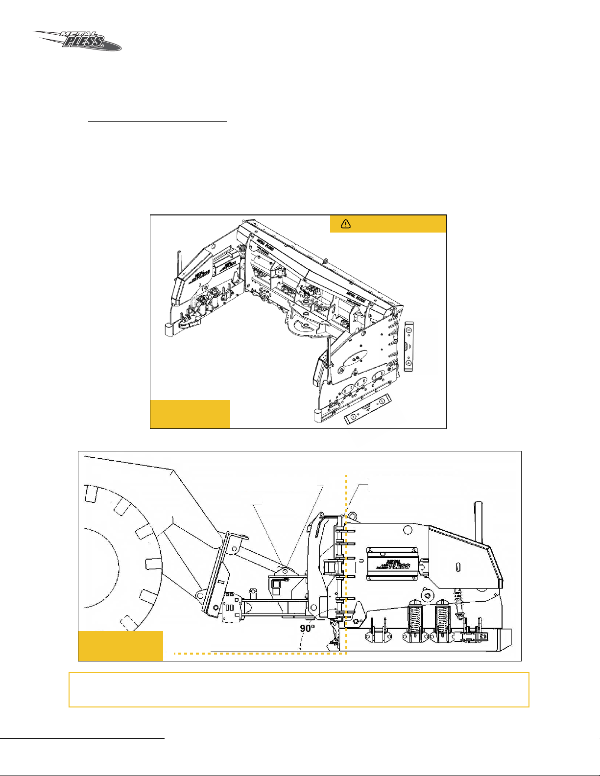
8.1 LEVELLING THE PLOW
In order to operate the equipment properly and also in order to avoid premature
wear of this equipment, it is imperative that the plow is level and square to the
ground during operations. (Fig. 3) The plow must sit 90 degrees square to the
ground when considering the angle of the pin that allows the wings to rotate onto the
mouldboard versus the ground. (Fig. 4)
Operating the equipment that is not properly set or level can cause premature wear
of the edges and result in high maintenance costs.
Fig.3
Fig.4
The wing pin
Ground
Centered
in slot
Mechanical float
WARNING
MAXXPRO 14
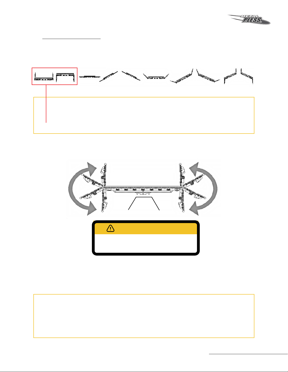
8.2 HYDRAULIC WINGS
The snowplow may be configured in different ways using its hydraulic power. Always
configure the wings and plow with caution.
This equipment has two (2) hydraulic wings, one on each side of the blade. The wings
can be articulated 180 degrees. Onyly use hydraulic power to rotate the wings. Never
try to exceed limitations of the wing’s rotation.
IMPORTANT: Always keep the hydraulic wings slightly open. Avoid working in the
fully closed position.
Operating the snowplow with the wings in a fully boxed position may create
damage to the surface and severly increase wear to the equipment.
Warning : Hydraulic wings may come in contact with the tires of the vehicle it is
attached to. The operator must exercise caution and adjust the position of the
wings to prevent them from coming in contact with the tires. Metal Pless shall not
be liable for any damages caused to tires.
BE CAREFUL. DO NOT OPERATE THE HYDRAULIC
WINGS IF SOMEONE IS STANDING NEARBY.
180˚ 180˚
WARNING
Operation of the diverter valve is controlled by either a two button joystick grip or
a three position rocker switch. It is important to note that the rocker switch must
remain in the center position when the hydraulic wings are not in use to avoid
burning out the DIN connectors or the wiring harness.
Owner’s Manual
15
EXCESSIVE PRESSURE ON THE SNOW PLOW
MAY CAUSE PREMATURE WEAR AND MAY CAUSE
ADDITIONAL COSTS.
WARNING
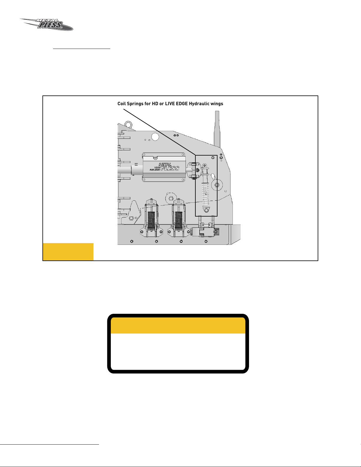
8.3 COIL SPRINGS
Coil springs are installed on each side wing of this equipment, as shown below.
Such coil springs allow limited movement of the abrasion shoe while maintaining
down pressure onto the ground. (Fig. 5).
Fig.5
Coil Springs for HD or LIVE EDGE Hydraulic wings

MAXXPRO 16
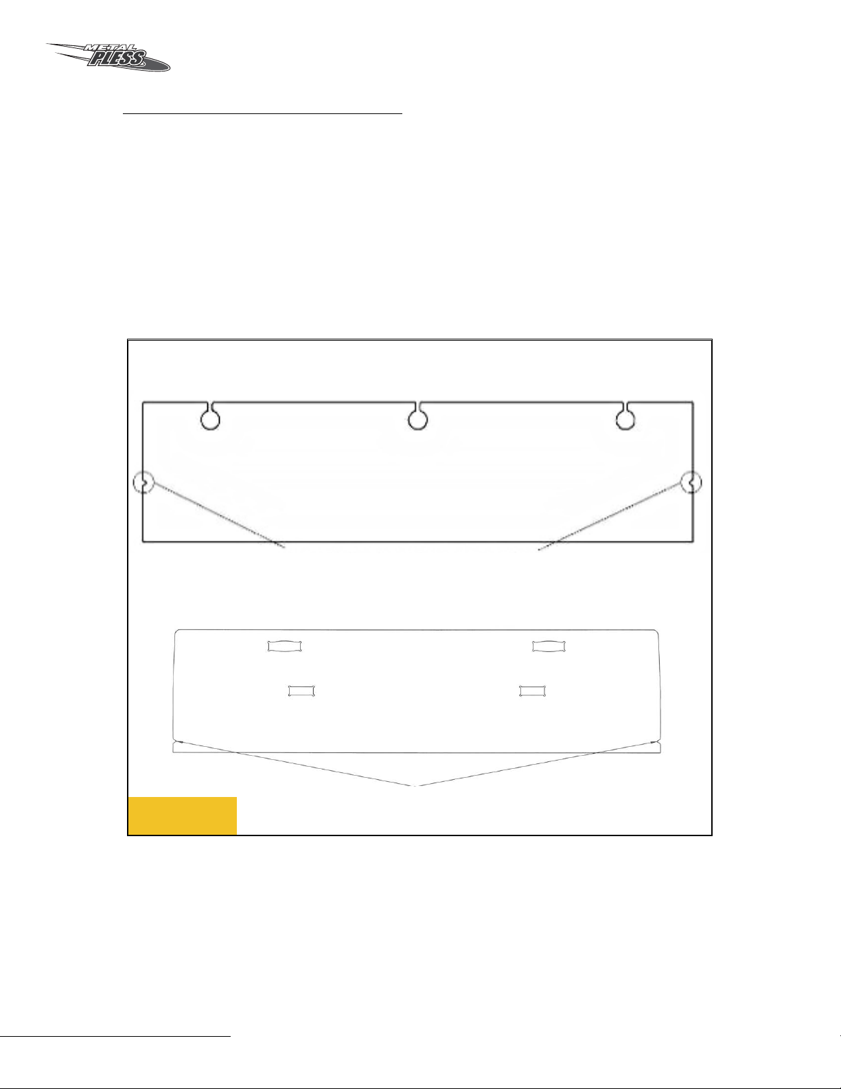
8.4 VISUAL MARKERS
A visual marker (Fig.5) is installed on each wing. The marker allows the operator of
the vehicle to establish a visual cue in width, height and space before the passage.
The markers serve ONLY as a guide and should in no way be taken to the exact value
of its position. The markers are bolted and use pre-perforated holes.
8.5 VISUAL MARKERS WITH LEVELING INDICATORS
On certain models an additional option may be available for the visual markers to of-
fer a self leveling indicator. By positionning both markers at an equal height the plow
is set level to the ground (Fig.4).
8.6 CUTTING EDGES (WEAR)
The cutting edges are considered wear parts. On this equipment, friction and
abrasion will lead to wear of the cutting edges. Depending of the type surface, the
outdoor temperature, the speed and how the user operates the equipment, the
cutting edge’s may wear at a much faster rate than normal.
A trained operator will use the appropriate amount of pressure. Too much pressure
will lead to premature wear. The maximal wear point is indicated by a groove cut into
the cutting edges. (Fig. 8)
Fig.6 Fig.7
(Fig.6-7)
Owner’s Manual
17
Fig.8
Standard and HD cutting edge
LIVE EDGE cutting edge
Replacement brands
Replacement brands
8.7 CUTTING EDGES (REPLACEMENT)
On HD models, it will be necessary to replace the abrasion shoes on the wings at the
same time as the replacement of the main cutting edges of the blade. (Fig.8)
On live edge models, it is common to replace only the abrasion shoes multiple times
prior to requiring the replacement of the live edge sections on the main blade.
This manual suits for next models
28
Table of contents
Popular Farm Equipment manuals by other brands


Posch
Posch SpaltAxt 8 operating instructions

JBT
JBT LEKTRO 88 Series Operation manual

sitrex
sitrex SR 420/11 H Use and Maintenance Spare Parts List

Spudnik
Spudnik 5140 Owner's/operator's manual

Schmeiser
Schmeiser VINEYARD DRILL 2nd GENERATION 98 Series Assembly & parts manual

albutt
albutt F470 INSTRUCTION MANUAL AND PARTS CATALOGUE