6
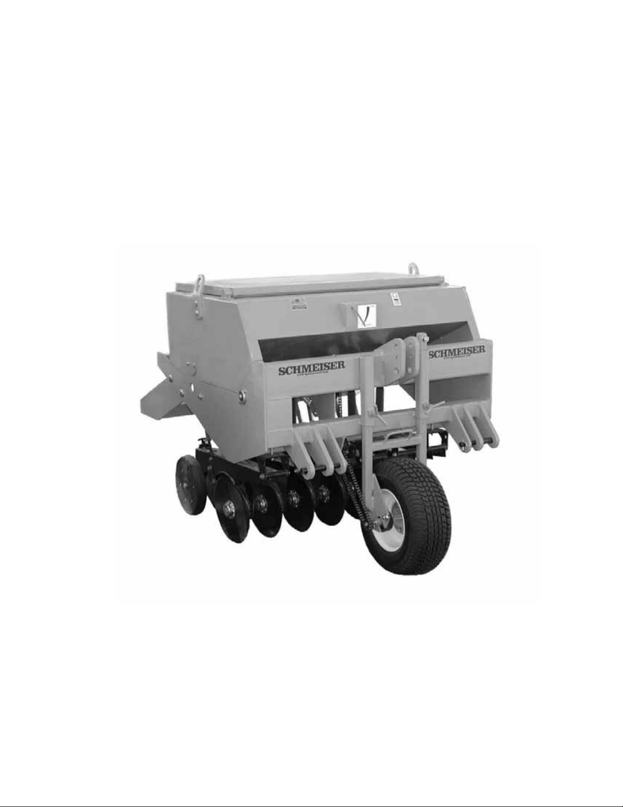
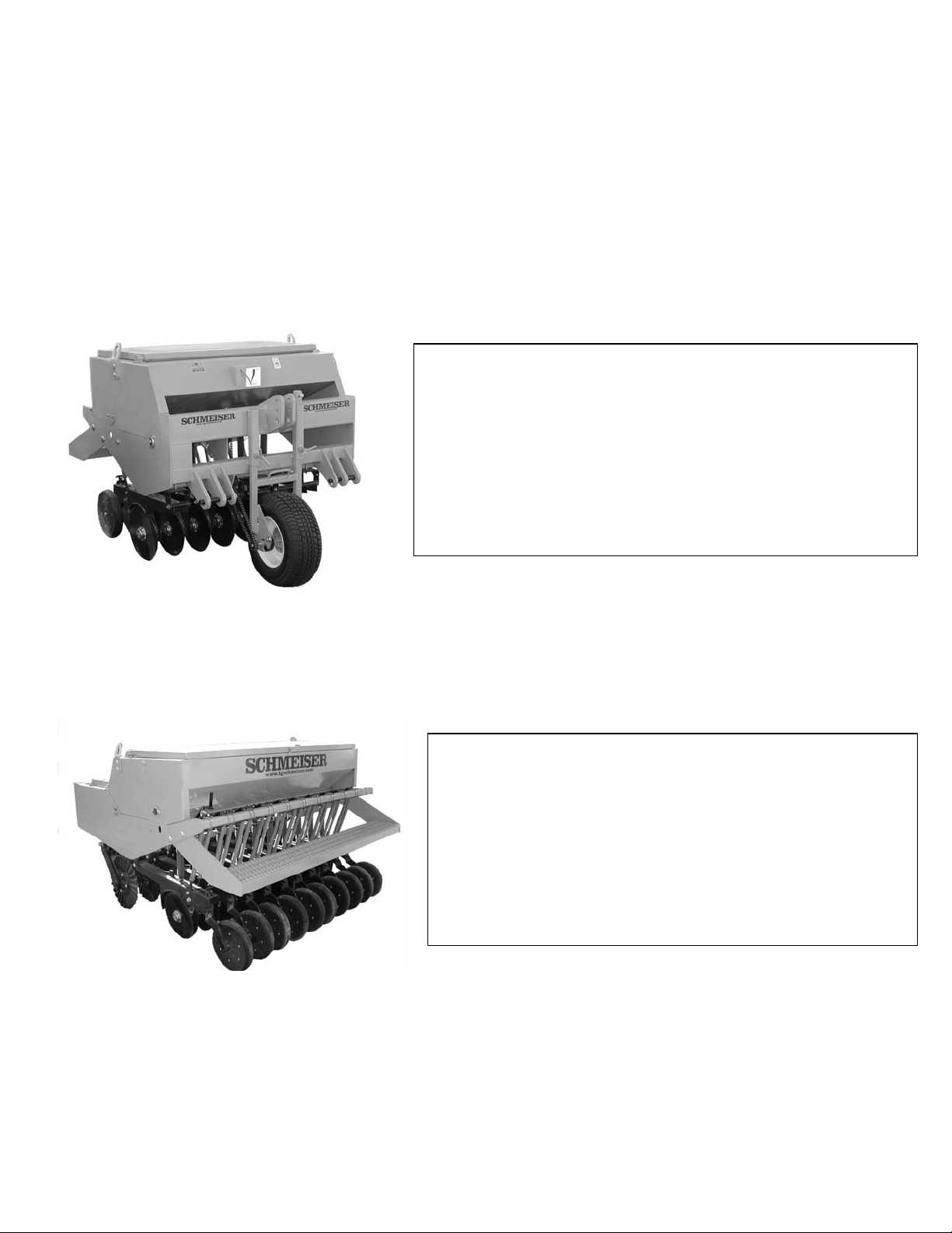
SCHMEISER VINEYARD DRILL
SEED RATE CALIBRATION
Note: Seeding rates will vary greatly with variations in sizes of seeds. Although the seeding rates listed
in this manual are based on an average seed size, we recommend that you test and adjust your Vineyard
Drill using the procedures listed below.
1) There are many factors, which will affect seeding rates: Seed treatment, weight of seed,
size of seed, surface condition of seed, tire configuration and pressure, and tire slippage.
Minor adjustments will probably be needed to compensate for the above factors.
2) The rates listed in the seed charts are based in the gauge wheel drive having 20.5 x 8.0
x 10 tire with the recommended tire inflation.
3) The large difference in seed size and treatment can cause a wide variation in actual seeding rates.
The rate charts are based on average size seed. This may differ from the seed you are using. Use the
seed rate charts as a guide only. Set the pounds per planted acre desired at the indicator number and
complete the following procedure to calibrate the rate for specific seed.
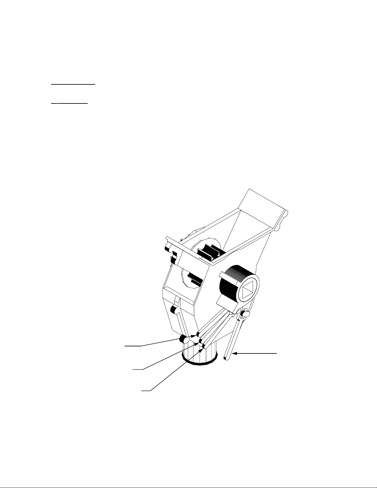
a. Place several pounds of seed over three feeder cups at the outboard end of the
Vineyard Drill.
b. Pull the seed tubes out of these three drops.
c. Raise the drive wheel off the ground.
d. Rotate the tire to see that the drive system is working properly and that the
feed cups are free from foreign matter.
e. Place a container under the three seed tubes to gather seed as it is metered.
f. On 3 ft. wide models rotate the tire 54 times to obtain 1,000 square feet. On 4 ft. wide models
rotate the tire 48 times to obtain 1,000 square feet. On 5 ft. wide models rotate the tire 38 times
to obtain 1,000 square feet. On 6 ft. models rotate the tire 32 times to obtain 1,000 square feet.
Be sure to check the three feeder cups to make sure each cup has plenty of seed coming into it.
g. Weigh the seed, which has been metered. Divide by three. This will give you the
ounces/pounds metered by each feeder cup. Multiply by the number of cups on your Vineyard
Drill to arrive at the total pounds per 1,000 square feet. Now multiply by 43.56 to arrive at the
total pounds per planted acre. If this figure is different than desired, set your feed cup
adjustment lever accordingly.
4) You may want to repeat the calibration procedure if the results of your calibration vary
greatly from the suggested settings contained in this manual.
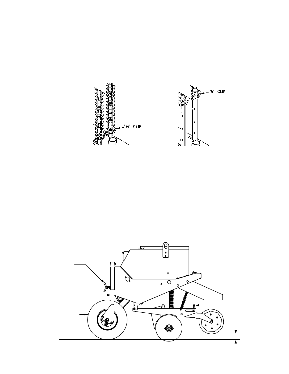
REMEMBER: Tire size and field conditions will also affect seeding rates. Be certain that your
Vineyard Drill tires are 20.5 x 8.0 x 10 and that they have the proper inflation. When seeding, check the
amount of seed you are using by noting area seeded, amount of seed added to box, and level of seed in
seeder box. If you suspect that you are seeding more or less seed than desired, and you have accurately
calibrated the Vineyard Drill to your seed, you may need to adjust the seeding rate slightly to compensate
for your field conditions.