Metallkraft AKM Series User manual
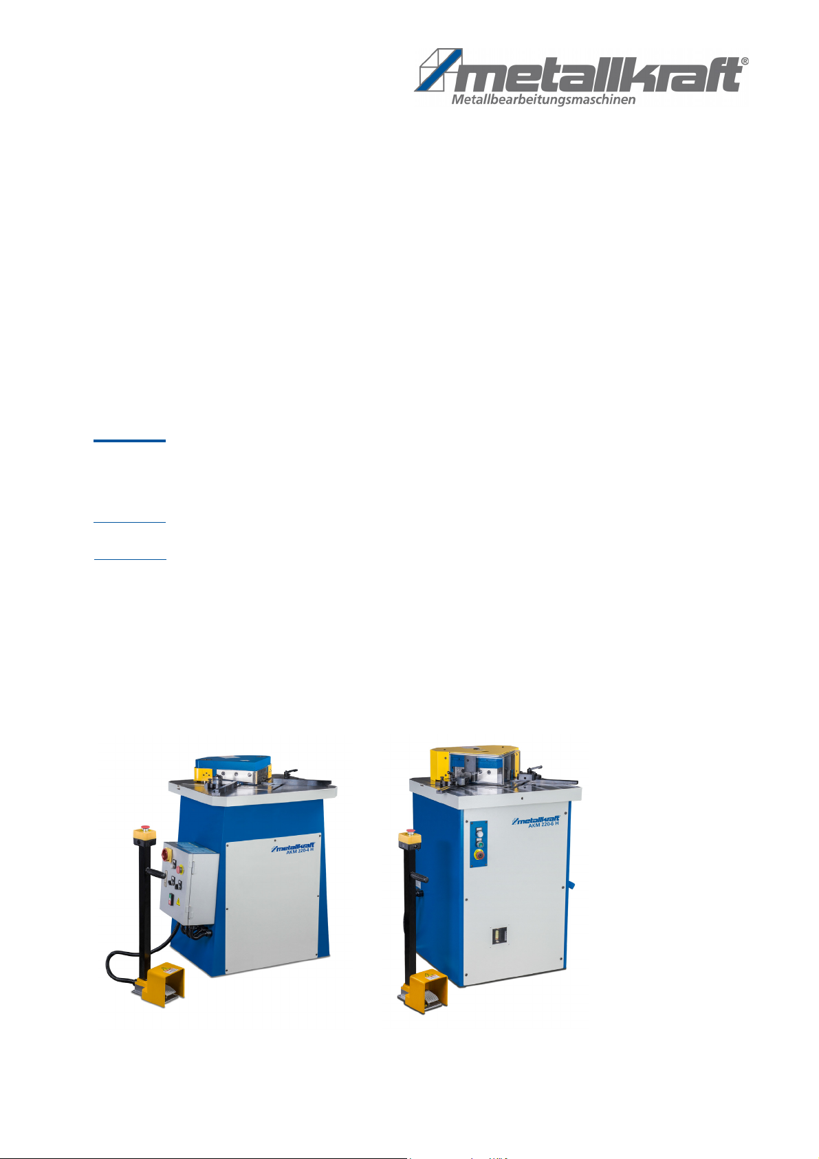
AKM 220-4 H
Operating Instructions
AKM 220-4 H
AKM-SERIES
Hydraulic Notching Machine
AKM 220-6 H
AKM 220-6 H

2AKM-Series 220 | Version 1.07
Imprint
Product identification
Hydraulic Notching Machine Item number
AKM 220-4 H 3834200
AKM 220-6 H 3836200
Manufacturer
Stürmer Maschinen GmbH
Dr.-Robert-Pfleger-Str. 26
D-96103 Hallstadt
Fax: 0049 (0) 951 96555 - 55
E-Mail: [email protected]
Internet: www.metallkraft.de
Indications regarding the operating instructions
Original instructions
Publication: 29.04.2019
Version: 1.07
Language: English
Author: SN
Indications regarding the copyright
Copyright © 2019 Stürmer Maschinen GmbH, Hallstadt,
Germany.
The contents of these operating instructions is the sole
property of the company Stürmer Maschinen GmbH.
Passing on as well as copying of this document, the use
and distribution of its content are prohibited if not expli-
citly permitted. Contraventions are liable to compensa-
tion.
Subject to technical modifications and error.
Content
1 Introduction .............................................................3
1.1 Copyright............................................................ 3
1.2 Customer service................................................ 3
1.3 Limitation of liability ............................................ 3
2 Safety........................................................................3
2.1 Symbol explanation ............................................ 3
2.2 Obligations of the operating company............... 4
2.3 Requirements to staff.......................................... 4
2.4 Personal protective equipment........................... 5
2.5 General safety regulations.................................. 5
2.6 Safety labels on the machine ............................. 6
2.7 Safety devices .................................................... 6
3 Intended Use............................................................7
3.1 Improper use ...................................................... 7
3.2 Residual risks ..................................................... 7
4 Technical Data.........................................................8
4.1 Table................................................................... 8
4.2 Type plates......................................................... 8
5 Transport, packaging, storage...............................9
5.1 Delivery and transport ........................................ 9
5.2 Packaging......................................................... 10
5.3 Storage ............................................................. 10
6 Description of device............................................10
6.1 Representation ................................................. 10
6.2 Scope of delivery.............................................. 10
6.3 Accessories...................................................... 10
7 Setting up...............................................................11
7.1 Place of installation........................................... 11
7.2 Electrical connection ........................................ 12
8 Settings ..................................................................14
8.1 Setting the cutting gap tolerance ..................... 14
8.2 Changing the knife ........................................... 15
8.3 Cutter bar - Stroke limit..................................... 17
8.4 Setting the limit stops ....................................... 17
9 Operation ..............................................................19
9.1 Control panel .................................................... 20
9.2 Functional description: ..................................... 20
9.3 Initial commissioning ........................................ 20
9.4 Workflow ........................................................... 21
9.5 Shut down the machine .................................... 21
10 Maintenance and repair ......................................21
10.1 Cleaning and lubricating the machine ........... 22
10.2 Maintenance of the machine .......................... 22
10.2.1 Hydraulic system..................................... 22
10.2.2 Lubrication diagram ................................ 23
10.2.3 Maintenance and inspection intervals .... 24
11 Disposal, recycling of used device....................24
11.1 Decommissioning........................................... 24
11.2 Waste disposal of electric equipment ............ 24
11.3 Disposal of lubricants..................................... 24
12 Disturbances, possible causes and measures.25
13 Sparte parts .........................................................26
13.1 Ordering spare parts ...................................... 26
13.2 Spare parts drawings ..................................... 27
14 Wiring diagrams ..................................................29
14.1 Electrical circuit diagrams............................. 29
14.2 Hydraulic circuit diagram .............................. 30
15 EC Declaration of Conformity ............................31

Introduction
AKM-Series 220 | Version 1.07 3
1Introduction
You have made a good choice by purchasing the notch-
ing machine made by METALLKRAFT.
Thoroughly read the operating instructions before commission-
ing the machine.
It informs you about the proper commissioning, the in-
tended use as well as the safe and efficient operation
and maintenance of your notching machine.
The operating instructions are part the notching ma-
chine. Always keep it at the place of use the notching
machine. Furthermore, the local accident prevention
regulations and the general safety notes are applicable
for the field of application the notching machine.
The illustrations in these operating instructions serve the
general comprehension and may deviate from the ac-
tual type.
1.1 Copyright
The contents of these instructions are copyright. Their
application is admissible in the frame the notching ma-
chine utilisation. An application beyond the described
application is not allowed without written approval of the
manufacturer. For the protection of our products, we
shall register trademark, patent and design rights, as
this is possible in individual cases. We strongly oppose
any infringement of our intellectual property.
1.2 Customer service
Please contact your dealer if you have questions con-
cerning your notching machine or if you need technical
advice. They will help you with specialist information
and expert advice.
Germany:
Stürmer Maschinen GmbH
Dr.-Robert-Pfleger-Str. 26
D-96103 Hallstadt
Repair service :
Fax: 0049 (0) 951 96555-111
E-Mail: service@stuermer-maschinen.de
Spare part orders:
Fax: 0049 (0) 951 96555-119
E-Mail: ersatzteile@stuermer-maschinen.de
We are always interested in valuable experience and
knowledge gained from using the application-which
then could be shared and be valuable to develop our
products even further.
1.3 Limitation of liability
All information and notes in these operating instructions
were summarised taking the applicable standards and
rules, the state-of-the-art and our long-term knowledge
and experiences into consideration.
In the following cases the manufacturer is not liable for
damages:
- Non-observance of the operating instructions,
- Inappropriate use,
- Use of untrained staff,
- Unauthorised modifications,
- Technical changes,
- Use of not allowed spare parts.
The actual scope of delivery may deviate from the ex-
planations and presentations described here in case of
special models, when using additional ordering options
or due to latest technical modifications.
The obligations agreed in the delivery contract, the gen-
eral terms and conditions as well as the delivery condi-
tions of the manufacturer and the legal regulations at the
time of the conclusion of the contract are applicable.
2 Safety
This paragraph will give you an overview of all important
safety packages for the protection of persons as well as
for the safe and undisturbed operation. Other task-
based safety notes are included in the individual chap-
ters.
2.1 Symbol explanation
Safety instructions
The safety notes in these operating instructions are
highlighted by symbols. The safety notes are introduced
by signal words which express the concern of the risk.
DANGER!
This combination of symbol and signal words indi-
cates an imminently dangerous situation which may
lead to death or severe injuries if they are not
avoided.
WARNING!
This combination of symbols and signal words indi-
cates a possibly dangerous situation which may
lead to death or severe injuries if they are not avoi-
ded.
4AKM-Series 220 | Version 1.07
Safety
Tips and recommendation
It is necessary to observe the safety notes written in
these operating instructions in order to reduce the risk of
personal injuries and damages to property.
2.2 Obligations of the operating company
The operating company is the person who operates the
the notching machine for business or commercial rea-
sons by herself, or leaves it to a third party for use or ap-
plication, and who bears the legal product responsibility
for the protection of the user, the staff or for third parties.
Obligations of the operating company
If the the notching machine is used for commercial pur-
poses, the operating company of the notching machine
must comply with the legal working safety regulations.
Therefore, the safety notes in this operating manual, as
well as the safety, accident prevention and environment
protection regulations applying for the area of applica-
tion of the notching machine must be met. The following
applies in particular:
- The operating company must be informed about the
applying industrial safety regulations and further ana-
lyse hazards resulting from the special working condi-
tions at the place of use of
the notching machine
. She
must implement these in form of operating manuals for
the operation of
the notching machine
.
- During the entire lifetime the notching machine, the
operating company must verify whether the operating
manuals prepared by her correspond to the current
status of the regulations, and must adapt these if
necessary.
- The operating company must unambiguously regu-late
and determine the responsibilities for installa-tion, oper-
ation, troubleshooting, maintenance and cleaning.
- The operating company must ensure that all per-sons
who work with the notching machine, have read and
understood this manual. Furthermore she must in-
struct the staff in regular intervals and in-form them
about the hazards.
- The operator must provide the necessary protec-tive
equipment to the staff and order the use of the neces-
sary protective equipment in a binding way.
Furthermore the operating company is responsible to
keep the notching machine always in a technically flaw-
less state. Thus, the following applies:
- The operator must ensure that the maintenance in-
tervals described in this manual are kept.
- The operator must have all safety devices
checked regularly for their good working order
and their integrity.
2.3 Requirements to staff
Qualifications
The different tasks described in this manual represent
different requirements to the qualification of the persons
entrusted with these tasks.
Only persons reliable working procedures can be ex-
pected from, are allowed to perform all works. Persons
the responsiveness of which is affected by e. g. drugs,
alcohol or medication, are not allowed to work with the
machine.
The qualifications of the personnel for the different tasks
are mentioned below:
CAUTION!
This combination of symbol and signal words indi-
cates a possibly dangerous situation which may
lead to minor or light injuries if they are not avoided
ATTENTION!
This combination of symbol and signal words indi-
cates a possibly dangerous situation which may
lead to property and environmental damages if they
are not avoided.
NOTE!
This combination of symbol and signal words indica-
tes a possibly dangerous situation which may lead to
property and environmental damages if they are not
avoided.
Tips and recommendation
This symbol highlights useful tips and recommenda-
tion as well as information for all efficient and
trouble-free operation.
WARNING!
Danger in case of insufficient qualification
of the staff!
Insufficiently qualified persons cannot estimate the
risks while using the notching machine and expose
themselves and others to the danger of severe or
lethal injuries.
- Have all works only performed by qualified per-
sons.
- Keep insufficiently qualified persons out of the
working area.

Safety
AKM-Series 220 | Version 1.07 5
Operator
The operator is instructed by the operating company
about the assigned tasks and possible risks in case of
improper behaviour. Any tasks which need to be per-
formed beyond the operation in the standard mode
must only be performed by the operator if it is indicated
in these instructions and if the operating company ex-
pressively commissioned the operator.
Electrically qualified person
Electrically qualified person is due to their professional
training, knowledge and experience as well as knowl-
edge of the relevant standards and regulations, in a po-
sition to carry out work on the electrical systems and to
in-dependently recognize and avoid possible dangers.
Qualified personnel
Due to their professional training, knowledge and expe-
rience as well as their knowledge of relevant regulations
the specialist staff is able to perform the assigned tasks
and to recognise and avoid any possible dangers them-
selves.
Manufacturer
Certain works may only be performed by specialist per-
sonnel of the manufacturer. Other personnel is not au-
thorized to perform these works. Please contact our cus-
tomer service for the execution of all arising work.
2.4 Personal protective equipment
The personal protective equipment serves to protect
persons against impairments of safety and health while
working. The staff has to wear personal protective
equipment while performing different works on and with
the notching machine which are indicated in the individ-
ual paragraphs of these instructions.
The personal protective equipment is explained in the
following paragraph:
2.5 General safety regulations
Please observe the following points:
- Use the guards and secure them securely. Never
work without guards and keep them functional.
- Always keep the machine and its working environ-
ment clean. Provide adequate lighting.
- Always secure your workpiece when working with
suitable clamping devices. Ensure a sufficient con-
tact surface.
- Check that the fixed hand guards are correctly instal-
led.
- The design of the notching machine must not be
changed and it must not be used for purposes other
than those foreseen by the manufacturer.
- Never work under the influence of illnesses that im-
pair concentration, drugs, alcohol or medication.
- Keep children and persons unfamiliar with the notch-
ing machine away from their work environment.
- Do not pull the power cord to unplug the plug from
the outlet. Protect the cable from heat, oil and sharp
edges.
- Immediately eliminate malfunctions that reduce
safety.
- Protect the notching machine against humidity (short-
circuit hazard!)
- Before each use of the notching machine, make sure
that no parts are damaged. Damaged parts must be
replaced immediately to avoid sources of danger.
- Before starting the machine, make sure that there are
no dangerous environmental conditions for the ope-
rator which could pose a danger during operation.
- Make sure that there are no tools or objects inside or
on the machine before starting the machine.
- Do not overload the notching machine! You will work
better and safer in the specified performance range.
- Only use original spare parts and accessories in or-
der to avoid possible dangers and accident risks.
Protective goggles
The goggles protect the eyes from flying parts and
liquid splashes
Hearing protection
The hearing protection protect the ears from hea-
ring damage caused by noise..
Breathing protection
Breathing protection serve to protect the respiratory
tract and lungs from the absorption of dust particles.
Protective gloves
The protective gloves serve to protect the hands
against sharp components as well as against fric-
tion, abrasions or deep injuries.
Safety boots
Safety boots protect the feet from being crushed, fal-
ling parts and slipping over on slippery ground.
Protective clothes
Protective clothes are made of a tightly fitted fabric
without the protruding parts of low tear strength.
6AKM-Series 220 | Version 1.07
Safety
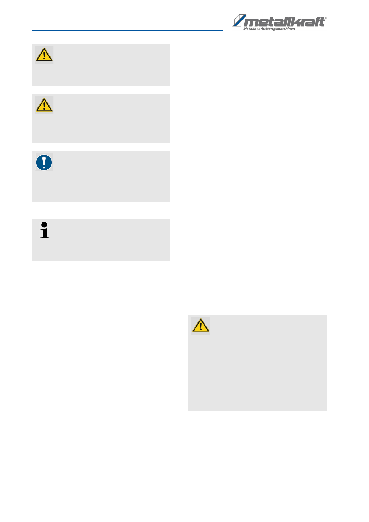
2.6 Safety labels on the machine
Safety labels and instructions are attached to the not-
ching machine (Fig. 1) which must be observed and
followed.
Damaged or missing safety symbols on the machine
can lead to incorrect actions with personal injury and
damage to property. The safety symbols attached to the
machine must not be removed. Damaged safety sym-
bols must be replaced immediately.
The machine must be taken out of operation until the
new labels are attached as soon as the labels are not
immediately recognisable and comprehensible at first
sight.
Fig. 1: Safety labels
2.7 Safety devices
WARNING!
Danger to life due to non-functioning safety
devices!
If the safety devices are not functioning or have
been rendered inoperative, there is a risk of serious
injury or even death.
- Before starting work, check that all safety devices
are functional and correctly installed.
- Never bypass or disable the safety devices.
- Ensure that all safety devices are always acces-
sible.
Intended Use
AKM-Series 220 | Version 1.07 7
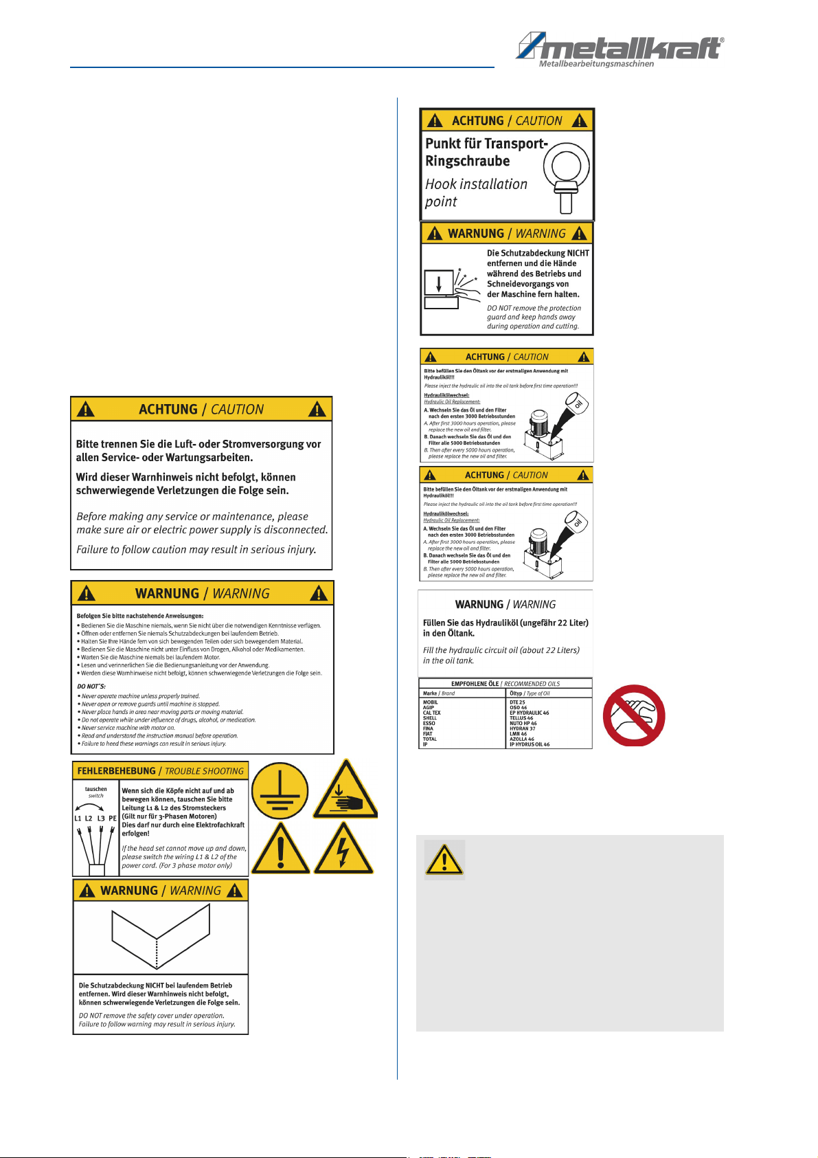
Emergency stop button
Press the emergency stop button (Fig. 2) located on the
control panel and the notching machine will stop imme-
diately. The power supply is switched off or the drives
are disconnected mechanically. After the emergency
stop button has been pressed, it must be unlocked by
turning it so that it can be switched on again.
Fig. 2: Emergency stop button
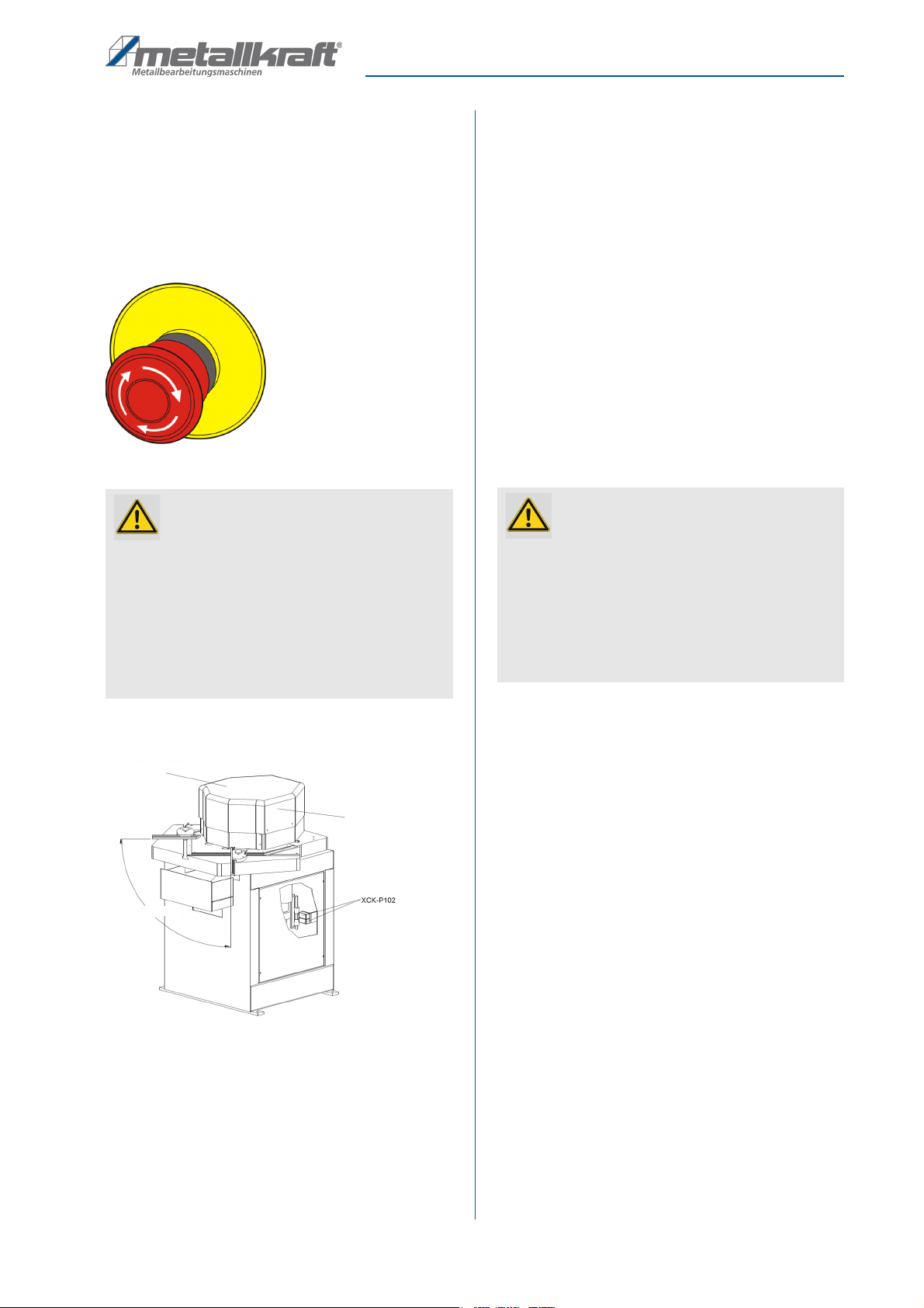
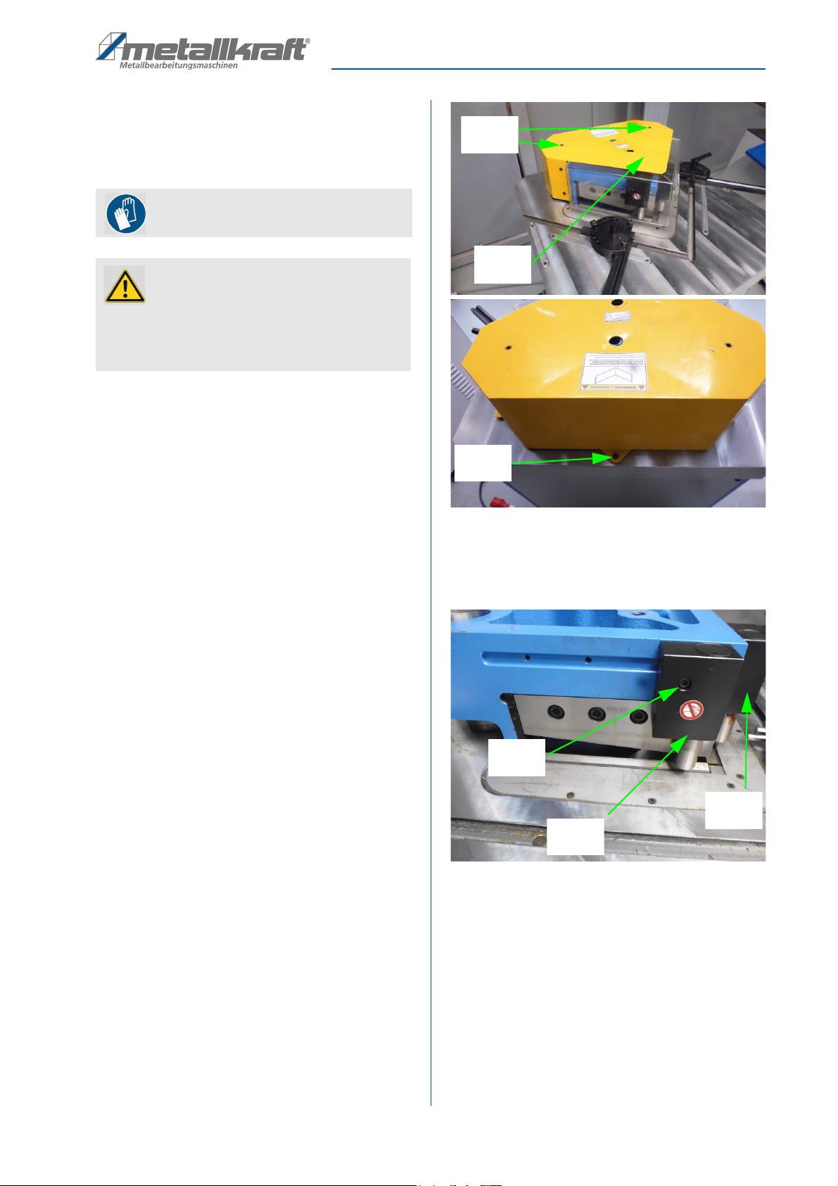
Safety covers and switch
Fig. 3: Safety devices
3 Intended Use
The notching machine is designed exclusively for not-
ching steel or stainless steel sheets. Notching is done
with a fixed angle (90°). The machine is intended and
suitable for commercial use. The machine must not be
used in explosive environments.
The proper use also includes observing all indications in
these operating instructions. Any use beyond the proper
use or any other use is regarded as misuse.
For structural and technical changes to the notching
machine the company Stürmer Maschinen GmbH assu-
mes no liability Claims of any kind due to damage due to
improper use are excluded.
3.1 Improper use
The notching machine must not be used for notching
materials made of light metals (e.g. aluminium or
similar).
3.2 Residual risks
Even if all safety instructions are observed, and the ma-
chine is put to its intended use, there are still residual
risks, which are listed below:
- Risk of injury of upper limbs while equipment is ope-
rating.
- Danger from the falling workpieces.
WARNING!
Risk of uncontrolled restart!
The uncontrolled restart of the machine can lead to
serious injuries.
- Before restarting, ensure that the cause of the
emergency stop has been eliminated and that all
safety devices have been fitted and are fully func-
tional.
- Only unlock the emergency stop button when there
is no longer any danger.
When servicing the
machine, remove the
safety cover. Do not
forget that the upper
body is movable.
Protect your bodies
against injuries.
Safety
cover
Safety switch
Work area
WARNING!
Danger in case of misuse!
Misuse of the notching machine can lead to dange-
rous situations.
- Only operate the notching machine in the power
rangelisted in the technical data.
- Never bypass or override the safety devices.
- Only operate the notching machine in a technically
perfect condition.
8AKM-Series 220 | Version 1.07
Technical Data
4 Technical Data
4.1 Table
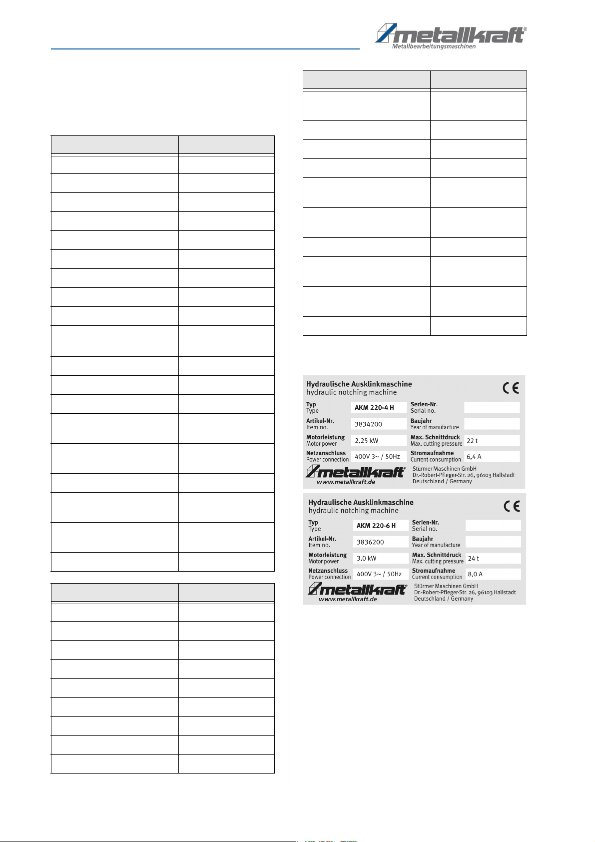
4.2 Type plates
Fig. 4: Type plates AKM 220
Technical Data Model AKM 220-4 H
Dimensions (LxBxH, max.) 1030x900x1050mm
Working pressure 100 bar
Motor output 2,25 kW
Total power consumption 6,4 A
Electrical voltage 400 V
Phase (s) 3 Ph
Mains frequency 50 Hz
Max. cutting pressure 22 t
Cutting area LxB 200x200 mm
Working table dimensions
LxB
700x600 mm
Notching angle 90°
Strokes 50 1/min
Hubverstellung 4 mm
Cutting capacity 90°
(400 N/mm²)
4 mm
Cutting capacity 90°
(600 N/mm²)
2 mm
Oil tank capacity 22l
Sound pressure level opera-
tion (1m distance)
70 dB
Sound pressure level no-
load (1m distance)
62 dB
Weight 375 kg
Technical Data Model AKM 220-6 H
Dimensions (LxBxH, max.) 860x860x1100mm
Working pressure 145 bar
Motor output 3 kW
Total power consumption 8 A
Electrical voltage 400 V
Phase (s) 3 Ph
Mains frequency 50 Hz
Max. cutting pressure 24 t
Cutting area LxB 220mmx220mm
Working table dimensions
LxB
650mmx650mm
Notching angle 90°
Strokes 15 1/min
Hubverstellung 6 mm
Cutting capacity 90°
(400 N/mm²)
6 mm
Cutting capacity 90°
(600 N/mm²)
3 mm
Oil tank capacity 35 l
Sound pressure level opera-
tion (1m distance)
70 dB
Sound pressure level no-
load (1m distance)
62 dB
Weight 495 kg
Technical Data Model AKM 220-6 H
Transport, packaging, storage
AKM-Series 220 | Version 1.07 9
5 Transport, packaging, storage
5.1 Delivery and transport
Delivery
Check the notching machine on delivery for any visible
transportation damage. If you notice any damage to the
device please report this immediately to the carrier or
dealer.
Transport
The notching machine may only be transported stan-
ding up and with the motor switched off.
Transport with a forklift/lift truck:
Always use a forklift with suitable lifting characteristics
for lifting the packaging, taking into account the weight,
when transporting the product in its packaged state:
- Adjust the forks so that the crate is properly balan-
ced (Fig.5).
- Place the crate on the floor.
- Remove the packaging from the machine.
For shipping,the notching machine is firmly mounted on
a pallet so that it can be transported with a forklift truck.
Fig. 5: Transport with a forklift/lift truck:
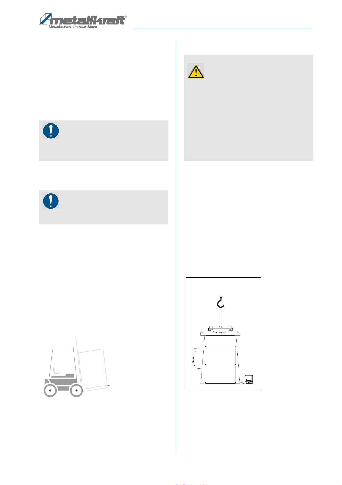
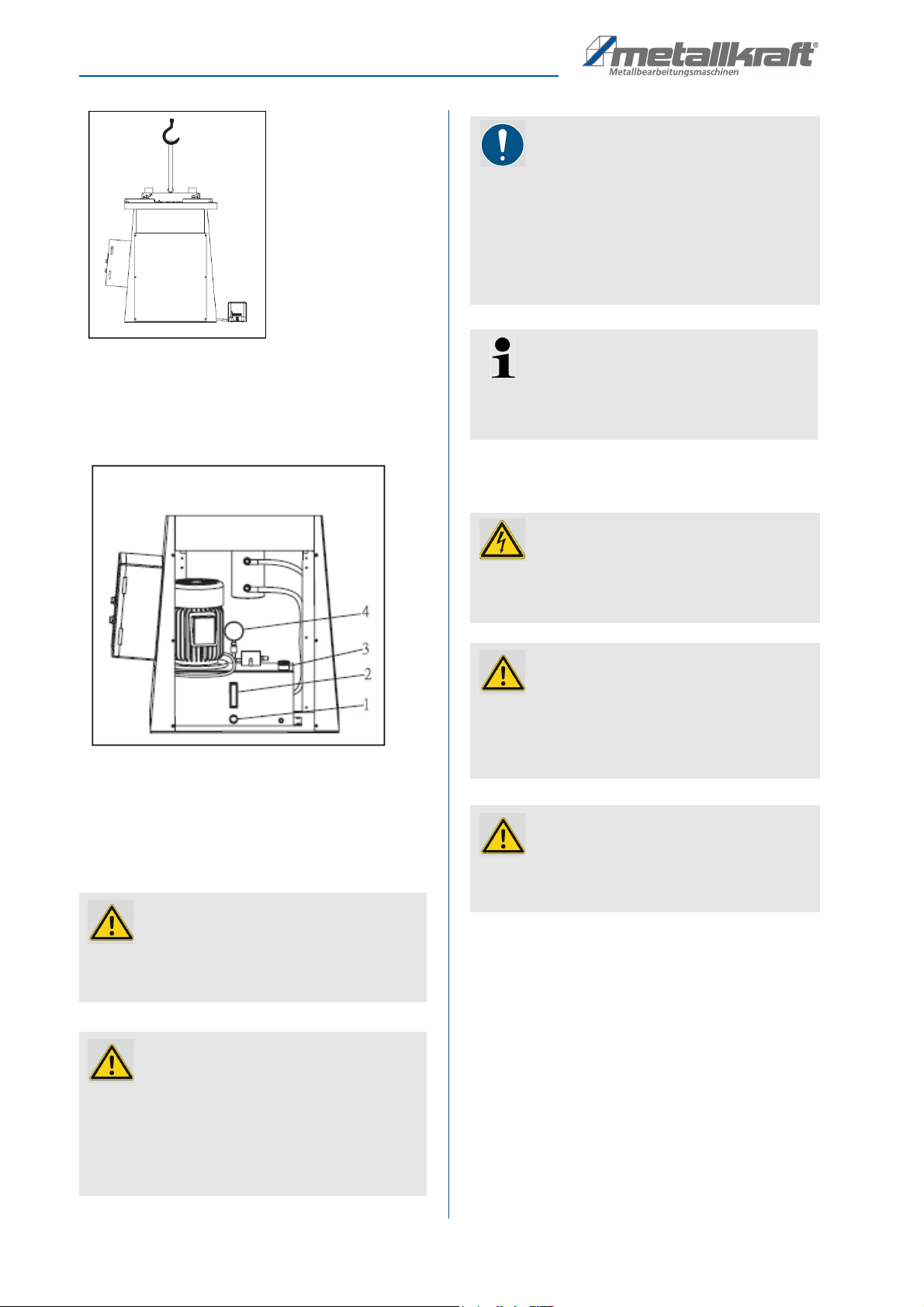
Transport with a crane:
- Remove the screws that secure the machine to the
pallet.
- Remove the reject container located on the machine
worktable to prevent it from falling to the floor while
moving. The container must be positioned on the
left side of the machine.
The machine may only be loaded and unloaded using a
rope. This rope must be attached to the eyebolt, which
must be placed on the top of the machine.
Never move the machine by hand or by any other me-
ans of transport not specified to avoid injury to persons
and damage to the machine.
Fig. 6: Transport with a crane:
On the top side of the notching machine a transport eye
can be attached in which the transport rope can be in-
serted (Fig. 6).
NOTE!
Oil may leak during transport of the notching ma-
chine. Secure the machine accordingly and take
precautions against possible environmental pollution.
NOTE!
The notching machine should be protected from hu-
midity.
WARNING!
Danger to life due to falling load!
If the weight of the notching machine and the per-
missible load capacity of the lifting equipment are
not observed during transport or lifting work, the
machine may tilt or fall.
- Transport with a crane may only be carried out by
specialists!
- When transporting and lifting, observe the weight of
the notching machine and also the permissible load
capacity of the lifting equipment.
- Use the intended attachment points for transport.
- The notching machine must not be rocked.
10 AKM-Series 220 | Version 1.07
Description of device
5.2 Packaging
All used packaging materials and packaging aids are
recyclable and should be taken to a materials recycling
depot to be disposed of.
The delivery packaging is made of cardboard, so
please dispose carefully by having it chopped up and
given to the recycling collection.
The film is made of polyethylene (PE) and the cushioned
parts of polystyrene (PS). Deliver these substances to a
collection point for recyclable materials or to the waste
disposal company which looks after your region.
5.3 Storage
Store the notching machine thoroughly cleaned in a dry,
clean and frost-free environment.
Apply protective oil to the upper and lower tools to pre-
vent rusting.
Protect the machine from sunlight.
Keep the machine packed in a suitable place, e.g. pro-
tected and not exposed to bad weather. If the machine
is to be taken out of operation for a short period of time,
clean it thoroughly and cover it with a cloth.
6 Description of device
6.1 Representation
Illustrations in these operating instructions are for basic under-
standing only and may differ from the actual version.
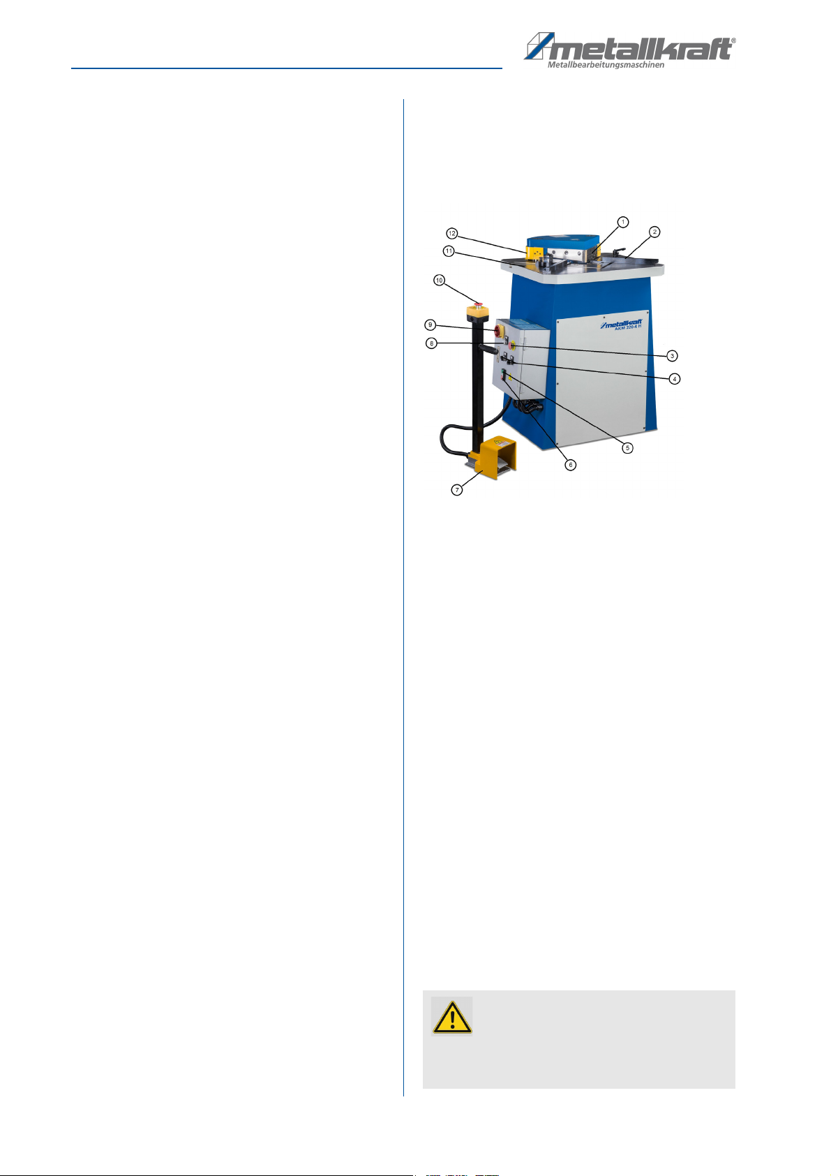
Fig. 7: Description of device AKM 220-4
1 Punching tool
2 Angle gauge
3 Emergency stop button
4 Selector switch „Operating mode“
5 Hydraulic ON
6 Hydraulic OFF
7 Foot control pedal
8 Control lamp
9 Main switch
10 Emergency stop button
11 Work table
12 Safety cover
6.2 Scope of delivery
- Hydraulic Notching Machine
- Foot pedal
- 2 adjustable angle stops
- Internal stop
- Operating instructions
- Bottom knife set for steel
- Top knife set for steel
6.3 Accessories
- Spare knife for steel (1 set)
ATTENTION!
The machine is delivered unfilled. Before commis-
sioning, hydraulic oil must be filled into the tank.
Only use suitable hydraulic oil for refilling.
Setting up
AKM-Series 220 | Version 1.07 11
7 Setting up
7.1 Place of installation
In order to ensure good functioning of the notching ma-
chine and a long service life, the installation site should
meet the following criteria.
- The notching machine may only be installed and
operated in dry, frost-free, well-ventilated rooms.
- Avoid places near machines that cause chips or
dust.
- The place of installation must be vibration-free, i.e.
away from presses, planing machines, etc.
- The ground must be suitable for the work. Pay atten-
tion to the bearing capacity and evenness of the
ground.
- If necessary, protruding parts, such as support ta-
bles, etc., must be secured by on-site measures so
that persons are not endangered.
- Provide sufficient space for set-up and operating
personnel and material transport.
- Also consider accessibility for adjustment and
maintenance work.
- Provide adequate lighting (minimum value: 300 lux).
- The humidity should be in the range of 10% to 90%
and the measured room temperature should be bet-
ween max. 0°C - 50°C.
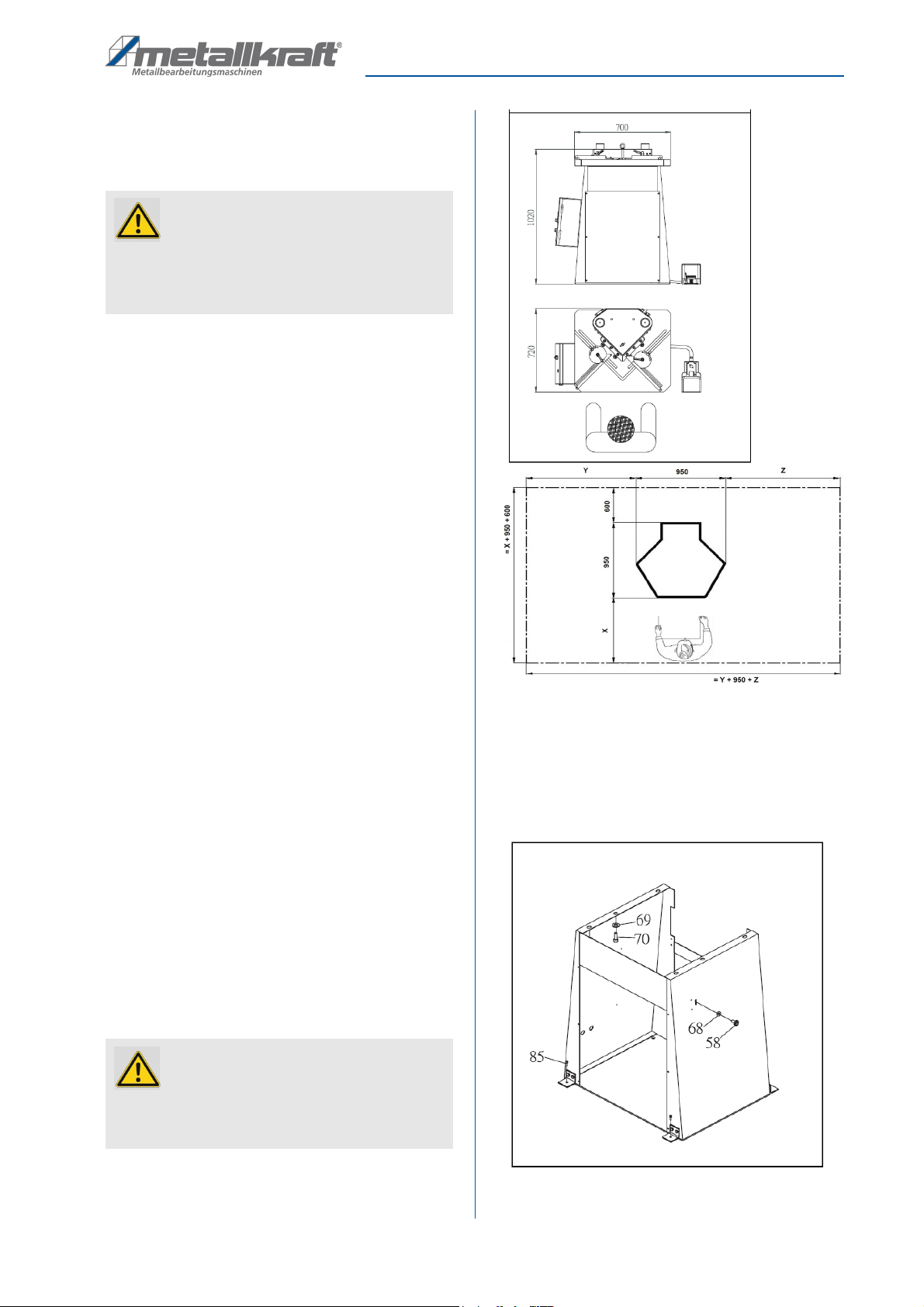
Setting up the machine:
Step 1: Make sure that the space around the machine is
sufficient for the application (Fig. 8). There must
be sufficient space for the operator and material
transport.
Step 2: Check each part of the machine for proper con-
dition before starting to set it up.
Step 3: Place the control foot pedal in the best position
for the application in front of the work area.
Fig. 8: Setup plan
Step 4: Remove the hexagonal head cap screws 85
(Fig.9).
Step 5: Use a crane to lift the machine from the pallet
and move it to the working position (Fig.10).
Fig. 9: Removing the fixing screws
ATTENTION!
Check the load-bearing capacity of the ground
before you install the machine. The installation place
must be capatable of bearing the weight of the
machine and the workpieces.
ATTENTION!
The machine is delivered unfilled. Before commis-
sioning, hydraulic oil must be filled into the tank.
Only use suitable hydraulic oil for refilling.
Stock area of
cutted material
Free clearance
space
Stock area of material
which will be cut
Free space for operation and
material feed/removal
Required minimum width
Required minimum depth
12 AKM-Series 220 | Version 1.07
Setting up
Fig. 10: Positioning with the crane
Step 6: Remove the front cover screws and front cover
(Fig.11).
Step 7: Remove the plug 3 (Fig.11).
Fig. 11: Filling the oil tank
Step 8: Fill the hydraulic oil into the hydraulic oil circuit
(approx. 20 litres) until the oil level reaches the
4/5 position of the oil level indicator 2 (Fig. 11).
Step 9: Check that the pressure gauge 4 (Fig. 11) is 150
kg/cm2(2100 psi).
7.2 Electrical connection
With the 3-phase 400 Volt / 50 Hz motor, the notching
machine should be connected to a standard 400V
mains supply.
Mains connection cable and extension cable must have
5 wires = 3P + N + PE (3/N/PE) with a cross-section of
1.5 mm² mm each.
ATTENTION!
The machine is delivered unfilled. Before commis-
sioning, hydraulic oil must be filled into the tank.
Only use suitable hydraulic oil for refilling.
ATTENTION!
When starting up the machine, only use the feet to
operate the foot pedal!
Never use your hands or any available aids to ope-
rate the machine via the foot pedal.
This will prevent injuries to persons and damage to
the machine.
NOTE!
After installation, remove the grease from the blank
metal parts which has been applied for protection.
- Use common solvent for this purpose, e.g. petroleum.
- Do not use water, nitro solvents, etc.!
After the machine has been thoroughly cleaned, all
blank parts must be lightly oiled. Only use resin- and
acid-free machine oil!
Tips and recommendations
For a safe stand, it is recommended that the
machine is fastened to a firm, stable and level
ground via the holes provided in the machine base.
Danger!
Risk of fatal electric shock!
Contact with live components may result in fatal
injury. Switched-on electrical components can make
uncontrolled movements and lead to serious injuries.
ATTENTION!
Never operate the foot pedal when:
- The electrical supply or air pressure supply is not
yet connected.
- Carry out maintenance.
ATTENTION!
All operations on the electrical installation and on the
electrical equipment may only be carried out by qua-
lified electricians!
Setting up
AKM-Series 220 | Version 1.07 13
Make sure that
- the power connection has the same characteristics
(voltage, mains frequency, phase position) as the
motor,
- the mains voltage of 400 V is used,
- a cable cross-section of at least 1.5 mm² is used for
the supply cable,
- the direction of rotation of the motor is correct (see
direction arrow on the motor).
- The unit must be earthed before operation so that in
the event of a malfunction or malfunction, the cur-
rent through the earthing goes the way of least resi-
stance. This reduces the risk of electric shock.
Wired grounded devices:
This device is factory equipped with a specific electrical
cable and plug to prevent the device from being
connected to an inappropriate circuit for use in an ordi-
nary power circuit.
Permanently connected devices:
In this case, the device must be connected to an eart-
hed metal, via a hard-wired wiring system.
Check motor direction of rotation:
Step 1: Check that the notching machine is switched off.
Step 2: Set the cutting gap setting to maximum ma-
nually.
Step 3: Connect the notching machine to the mains.
Step 4: Briefly switch the motor on and off again.
Step 5: Check the direction of rotation when the motor
runs out, see direction of rotation arrow.
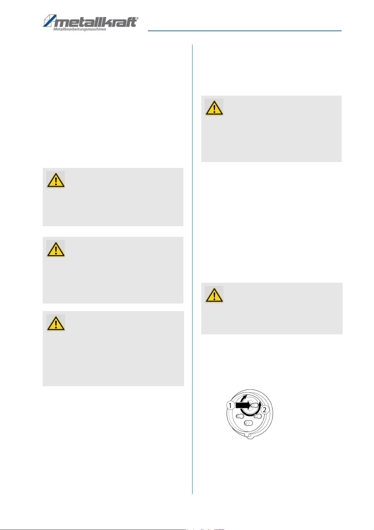
If the motor is rotating in the wrong direction:
Step 1: When equipped with a phase inverter:
Use a screwdriver to push in the washer in the
plug and turn it by 180°.
Fig. 12: Change motor direction of rotation
Without phase inverter:
Have two phases at the electrical connection re-
placed by a qualified electrician.
Step 2: Check the direction of rotation of the motor.
WARNING!
This device is equipped with a protective conductor
and an earthing cable.
The plug may only be connected to a suitable output
that is properly installed and earthed in accordance
with local laws and regulations!
WARNING!
An unsuitable connection of the earth conductor can
result in an electric shock!
Never make any changes to the grounding plug on
the device!
Only have modifications to the grounding plug car-
ried out by qualified personnel!
ATTENTION!
Danger of collision due to incorrectly set upper and
lower knives.
- Ensure that the upper or lower knives cannot collide
when the machine is switched on for the first time.
Have the upper knives dismantled by a specialist
or have the cutting gap on the lower knives increa-
sed accordingly.
WARNING!
Make sure that the socket has the same configura-
tion as the grounding plug!
Never use an adapter between the grounding plug
and the socket!
Have modifications to the grounding plug carried out
by qualified personnel only!
ATTENTION!
An incorrect direction of motor rotation will result in a
hydraulic fault!
Set the cutting gap to maximum before commissio-
ning.
14 AKM-Series 220 | Version 1.07
Settings
8Settings
8.1 Setting the cutting gap tolerance
The cutting gap is adjusted after initial commissioning
and after each knife change.
- If the cutting gap is set too large, the notching
process may result in burr and chip formation. If the
cutting gap is set too small, the knives may be da-
maged and the stroke may block.
- Perform a few test cuts after adjusting the cutting
gap.
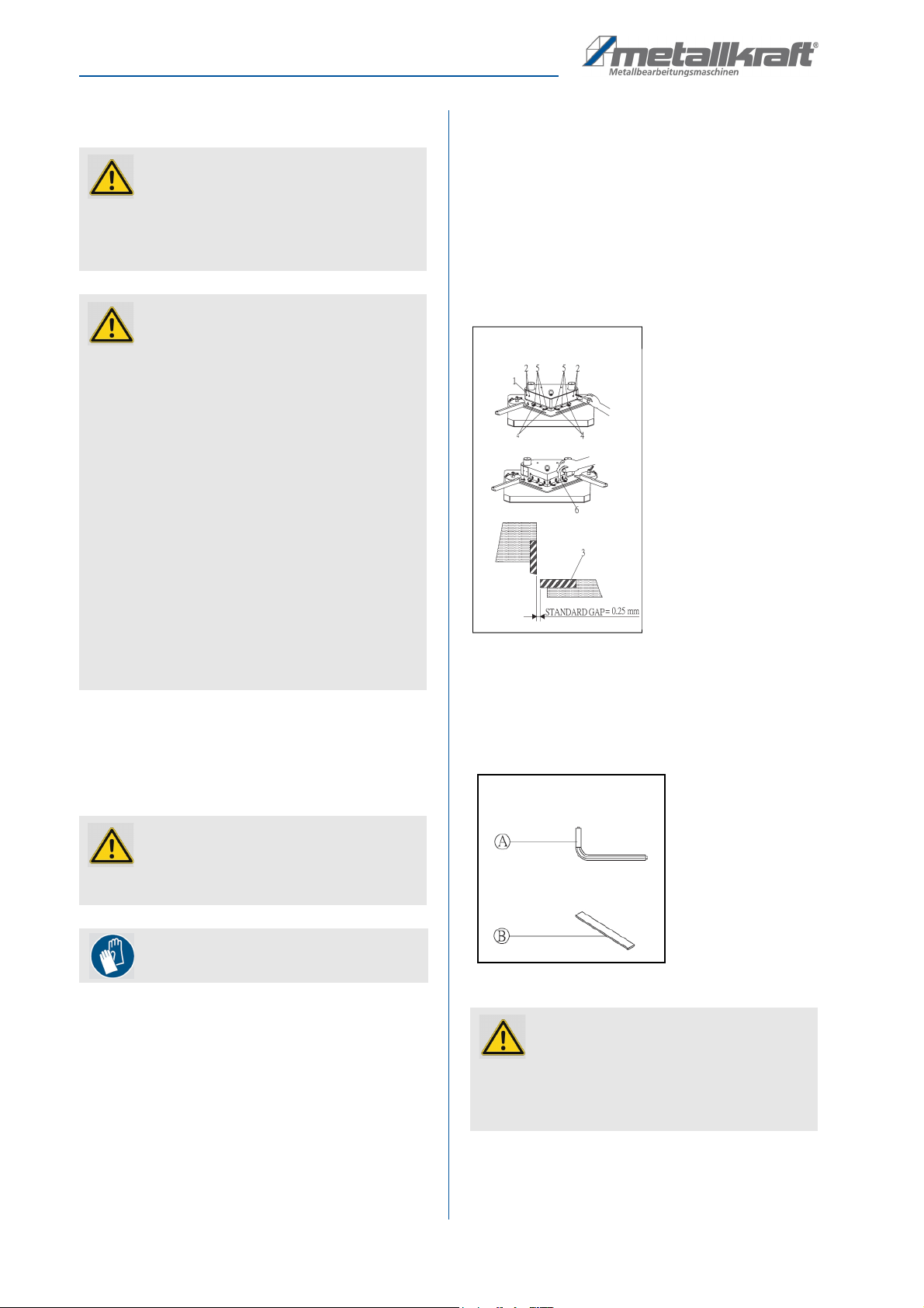
Step 1: Disconnect the power supply.
Step 2: Unscrew the screws (Pos. 2, Fig. 13) then re-
move the safety cover (Pos. 1, Fig. 13).
Step 3: Loose the bias screws (Pos. 4, Fig. 13) and
blade screws (Pos. 5, Fig. 13).
Step 4: Measure the tolerance by 0.25 mm thickness
gauge (Pos. 6, Fig. 13).
Step 5: Adjust the upper and lower blades against to the
thickness gauge. The thickness gauge should
be nower removed smoothly.
Step 6: Tight all the screws.
Fig. 13: Disassemble the safety cover
Tools for adjusting the cutting gap width (Fig. 14):
A - Allen wrench for blade screw
B- 0.25 mm thickness gauge.
Fig. 14: Tools for cutting gap adjustment
ATTENTION!
Settings on mechanically acting machine elements
may only be carried out on the machine by trained
specialists or specially trained and instructed per-
sons.
DANGER!
Incorrect mechanical settings can influence the
safety of the machine to such an extent that it cau-
ses a permanent danger. Careless behaviour can
put the personnel and the machine at risk when swit-
ching-on again.
- Before making any mechanical adjustments, al-
ways switch off the machine at the main switch and
secure the main switch against accidental restar-
ting, e.g. by attaching a warning sign.
- After carrying out the adjustment activities, make
sure that all covers and protective devices have
been properly mounted on the machine again.
- Do not leave any tools accidentally inserted during
setting activities. Before switching on the machine
again, make sure that all setting tools have actually
been removed. Make sure that no tools are left in-
side the machine, especially in the working area of
the machine mechanics.
ATTENTION!
There is a risk that the machine will be damaged if
the cutting gap is set incorrectly.
Use protective gloves!
ATTENTION!
No adjustment of the cutting gap is required for dif-
ferent sheet thicknesses. There are spring plates in
the system which automatically adjust the cutting
gap.
Settings
AKM-Series 220 | Version 1.07 15
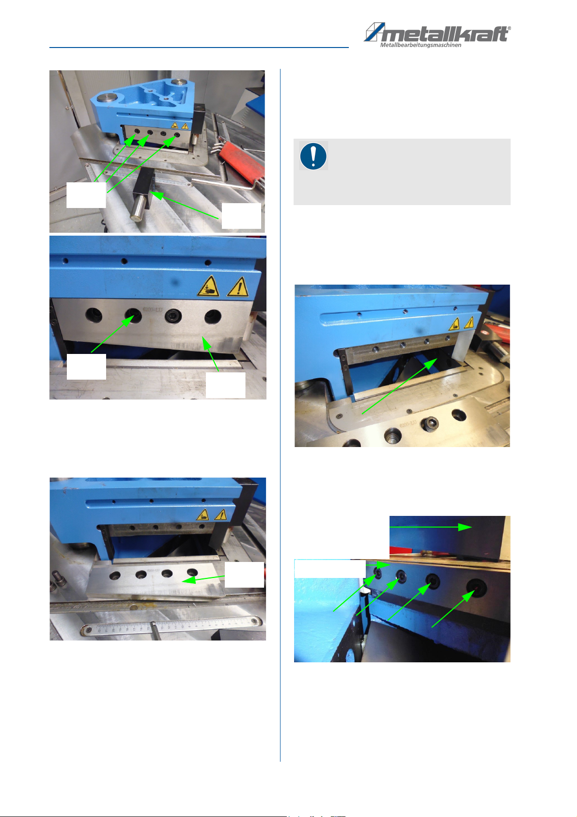
8.2 Changing the knife
Replace the knives in time. Blunt knives lead to poorer
cutting performance.
- Poor knife quality reduces the service life of the
knives.
- There is a danger that after a knife change the cut-
ting gap is incorrectly set and the machine is dam-
aged.
- Use protective gloves when changing the knives.
- After each knife change, make sure that the cutting
gap is within the permissible setting range of 0.25
mm.
- If necessary, readjust the cutting gap.
Replacing the upper knives:
Step 1: Move the knife bar to the upper end position and
switch off the machine by actuating the main
switch. Now secure the main switch against be-
ing accidentally switched on again.
Step 2: For removing the protective cover 1, you must
first unscrew the three screws 2 (Fig.15).
Step 3: Dismount the protective cover now. Lift the pro-
tective cover off the cutter bar and store it in a
safe place.
Fig. 15: Disassembling of the protective cover
Step 4: For disassembling the downholder device 3, un-
screw the corresponding fastening screw 4
(Fig.16).
Fig. 16: Change upper knife
Step 5: Remove the respective downholder and place it
at a sufficient distance to be able to disassem-
ble the upper knife (Fig.17) without any problem.
Use protective gloves!
CAUTION!
Use only the recommended original spare blades.
There is a risk that poorer material properties will
lead to knife breakage and cause injury and dam-
age to the machine.
2
2
1
4
3
3
16 AKM-Series 220 | Version 1.07
Settings
Fig. 17: Dissembling of the upper knife
Step 6: First unscrew the three screws (5, Fig.17).
Step 7: Finally unscrew the fourth screw (6, Fig.17).
Fig. 18: Removing of the upper knife
Step 8: Carefully remove the upper blade (7, Figs. 17
and 18) and store it in a safe place.
Step 9: Take the new upper blade and fasten it by first
screwing in the screw 6 (Fig.17).
Step 10: Then screw in the three screws 5 (Fig. 17).
When tightening all screws, make sure that there is no
gap at the points where the knives are in contact with
each other.
Replacing the lower knives:
First, perform steps 1 to 8 of the section „Replacing the
upper knives“. First disassemble only one upper knife.
Then continue with step 9 in the „Replacing the lower
knives“ section.
Fig. 19: Access to the fixing screws of the lower knife.
Step 9: After the upper knife has been removed, you
can use an Allen key to reach the screws of the
adjacent lower knife (Fig.19 or 20).
Fig. 20: Fixing screws of the lower blade
Step 10: Use a suitable Allen key (Fig.21) to unscrew the
screws and change the lower knife.
3
5
6
7
7
NOTE!
In order to enable the replacement of the lower
knives, first the adjacent upper knife must be dis-
mantled!
Untermesser
Obermesser der
angrenzenden
Seite (von hinten)
Settings
AKM-Series 220 | Version 1.07 17
Fig. 21: Unscrewing of the screws of the lower knife
Step 11: Mount the new lower knife.
Step 12: Check the cutting gap. If necessary, reset it im-
mediately.
Step 13: Mount the upper knife back again.
Step 14: Carry out all necessary steps to change the
second lower knife as well.
Step 15: If there are no further activities in the area of the
knives, replace the protective cover 1 (Fig.15)
and screw it tight.
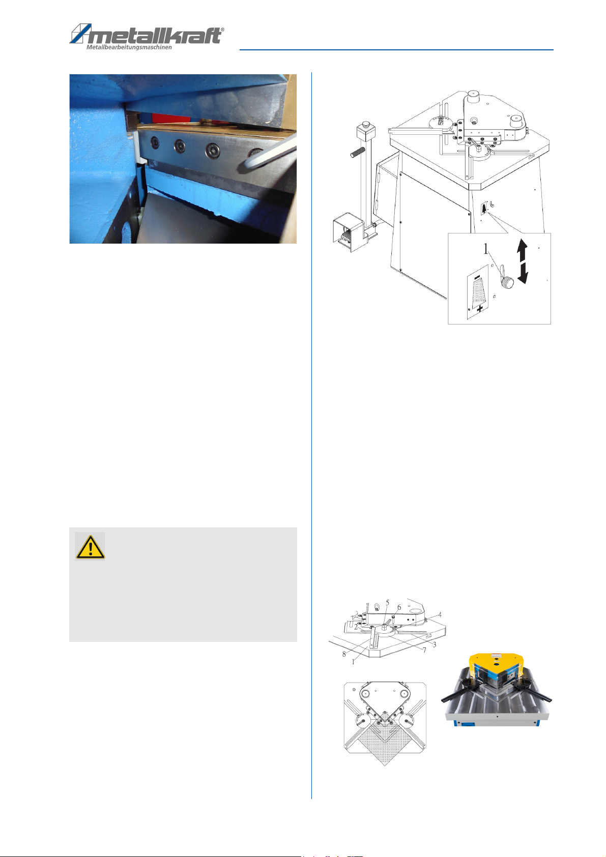
8.3 Cutter bar - Stroke limit
Setting of working head
The setting of the cutting depth, cutting speed and cut-
ting time is determined by the position of knob (Pos. 1,
Fig. 22).
The maximum travel of the cutter bar is 20 mm.
Fig. 22: Stroke limit
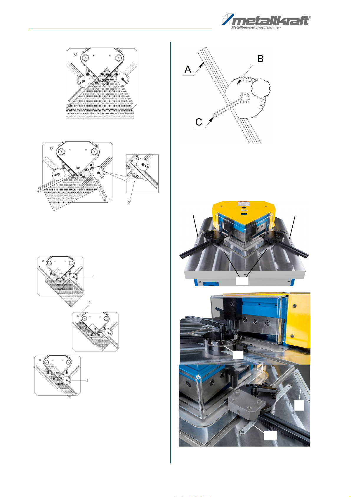
8.4 Setting the limit stops
Adjustable stops are used to limit or guide the process-
ing of the sheets.
Step 1: Move the cutter bar to the upper end position
and switch off the machine by pressing the main
switch. Now secure the main switch against ac-
cidental restarting.
Step 2: Set the currently required stops according to the
following information.
Use the setting examples as a basis for the cur-
rently required setting.
Step 3: Loosen the clamping handle (Pos. 5, Fig. 23)
and push the stop out to the required workpiece
length.
Step 4: Remove pin (Pos. 6, Fig. 23) and set the re-
quired number of degrees.
Fig. 23: Limit stops
ATTENTION!
- There is a risk that the machine will be damaged if
the knife bar stroke is set incorrectly.
- Improper adjustment may void the warranty.
- Repairs to the cutter bar stroke limit, such as the re-
placement of defective parts, may only be carried
out by qualified personnel!
18 AKM-Series 220 | Version 1.07
Settings
Fig. 24: Setting the limit stops
Step 5: Adjust the left and right stops (Pos. 8, Fig.23) to
fit the workpiece to the working reference
(Fig.24 and 25).
Fig. 25: Setting the limit stops
Adjustment elements
The stop bar A of the angle stops can be moved across
the T-slot. The angle of the stop bar to the measuring
tape is adjusted via the grid plate B (angle wheel).
Fig. 26: Adjustment elements
The clamping lever C
(Fig. 26) is used to fix the current set-
ting. The measuring tapes embedded in the table are each
provided with an outer and inner scale. The outer and inner
scales are each inclined by 45° to allow precise adjustment
of the stop bars.
Fig. 27: Scales
E
E
D
E
B
A
D
Operation
AKM-Series 220 | Version 1.07 19
B: Grid plate, angle wheel
D: Inner scale
E: Outer scale
.
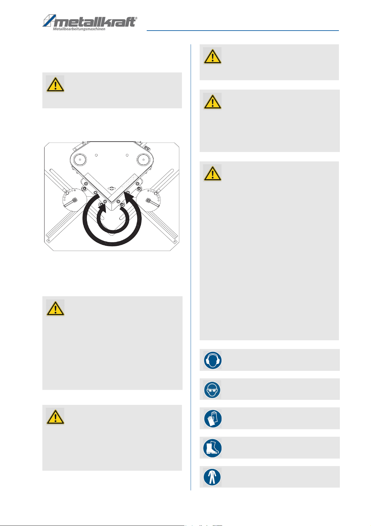
The two reference display groups can both be set to the
left and to the right within a range of up to 45°.
Fig. 28: Angle adjustment directions of the reference display groups
9 Operation
ATTENTION!
If the setting of the knife position is changed, the
position of the outer stop must be adjusted.
WARNING!
Danger to life!
Failure to observe the following rules entails a risk of
fatal injury for the operator and other persons.
- The operator must not work under the influence of
drugs, alcohol or medication.
- The operator must not work in case of tiredness or if
suffering from an illness that impairs concentration.
- Die Ausklinkmaschine must be operated by one
person only. Additional persons must keep out of
the work area during operation.
DANGER!
Risk of injury!
While working on the notching machine:
- tight clothing must be worn.
- No jewellery may be worn.
- No shawls, ties or the similar must be worn.
- A hair net must be worn for long hair.
DANGER!
Risk of injury!!
There is a risk of injury to the upper limbs (e.g.
hands, fingers).
ATTENTION!
Never step on the foot pedal if:
- You have connected the electrical supply and the
air pressure supply.
- You want to start the application during operation.
- You have completed a started maintenance.
ATTENTION!
- Never change the settings for the hydraulic system.
This is especially true for valves present there.
- Never change the setting of the cutter bar stroke li-
mit.
- Only operate the machine from the front.
- Ensure that the workpieces are fixed when working.
Use the stops for this purpose.
- Adjust the stops only when the machine is swit-
ched off (main switch in the position "OFF").
- When setting the stops, observe the minimum and
maximum cutting length.
- When adjusting the inner stop, make sure that no
collision with the upper knives can occur.
- When cutting metal strips to length, make sure that
the cutting line is not longer than the knife length.
- Always place the metal sheets over their entire sur-
face on the worktable. If necessary, support late-
rally protruding material with stable and stable ma-
terial stands.
Wear hearing protection!
Use protective goggles!
Use protective gloves!
Safety boots
Use protective clothes!
20 AKM-Series 220 | Version 1.07
Operation
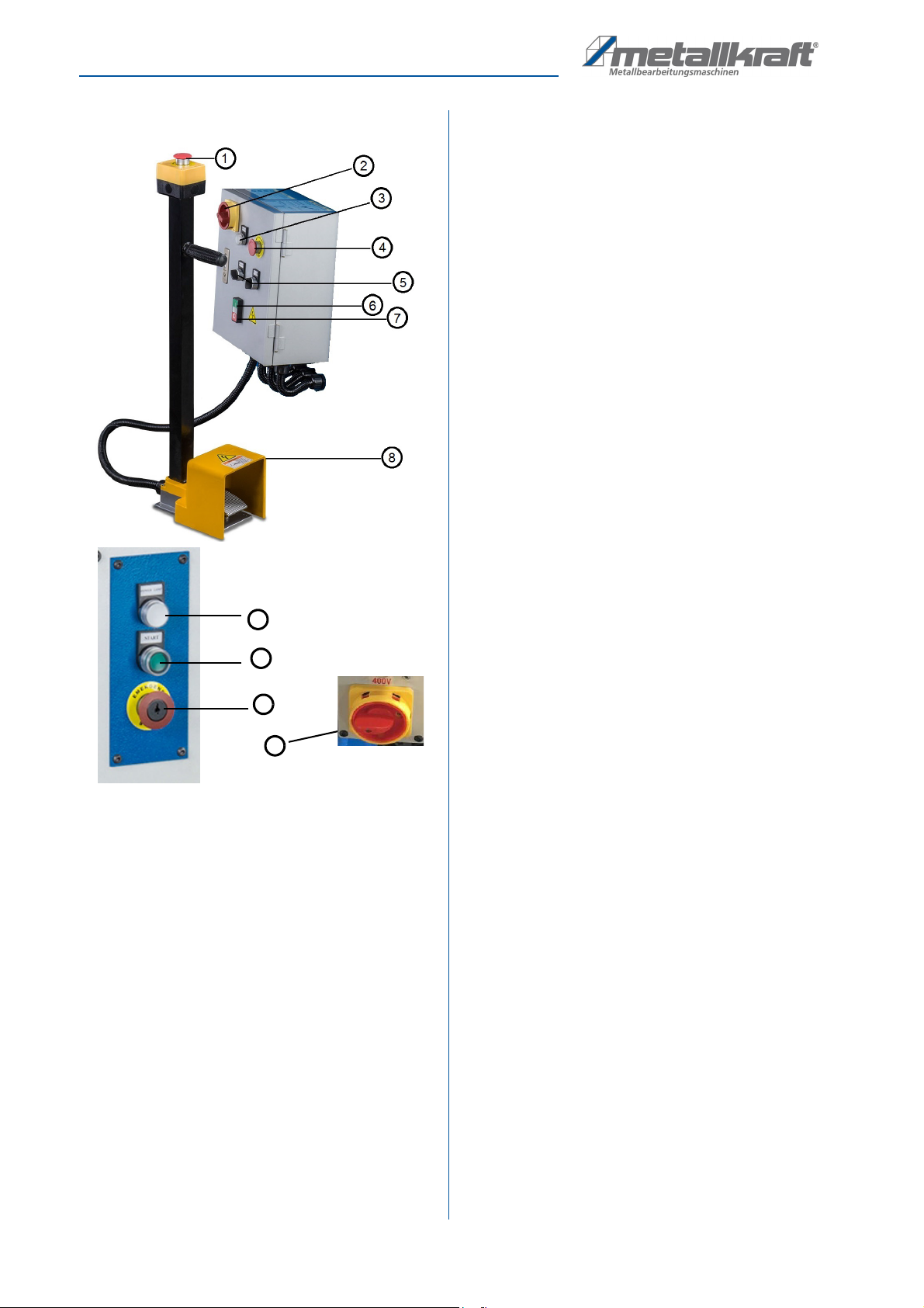
9.1 Control panel
Fig. 29: Control panels AKM 220-4 (top), AKM 220-6 (bottom)
1 Emergency stop button
2 Main switch
3 Control lamp
4 Emergency stop button
5 Toggle switch „Operating mode“
6 Hydraulics ON
7 Hydraulics OFF
8 Foot pedal
9.2 Functional description:
Main switch
Switches the machine on or off when actuated.
Emergency-stop button (pushbutton)
Used in a hazardous situation to switch off the ma-
chine quickly.
The emergency-stop button may only be operated in an
emergency!
Selector switch for operator with signal lamp
Switches the operating mode mode on or off depend-
ing on the switch position.
Selector switch for manual/foot operation with signal lamps
Activates manual or foot opetating mode depending
on switch position.
Button for manual upward movement of the cutter bar with
signal lamp
Moves the upper cutter bar upwards when manual
operation is switched on. Releasing the button stops
the upward movement (jog mode).
Foot pedal (freely adjustable)
When actuated, a working stroke is performed when
foot operation is switched on.
Button for angle adjustment with signal lamp
By turning the switch to the right while pressing the
pedal, you can adjust the angle by moving the angle
stops. To cut, turn the switch to the left.
9.3 Initial commissioning
Before you start the machine for the first time, make sure
that the following points are fulfilled:
- The machine is anchored to the ground at the instal-
lation site,
- The direction of rotation of the motor has been suc-
cessfully checked after connection to the mains,
- Enough hydraulic oil has been filled into the oil tank
to reach the upper level at the oil sight glass,
- The hydraulic system has been checked for proper
installation and safe functioning before initial opera-
tion in accordance with the German Ordinance on
Industrial Safety and Health (BetrSichV) - any de-
fects have been rectified,
- Upper and lower knives cannot (accidentally) col-
lide.
First familiarise yourself with all switching functions as
described in Chapter 7. Do not omit any switching func-
tion to ensure that you can operate all electrical controls
correctly during subsequent operation:
- Ensure that all protective devices are installed. The
side maintenance protection covers must be firmly
screwed to the machine.
- Make sure that the foot pedal is connected and can
be operated with the foot in front of the machine.
- Now switch on the main switch. The machine is
ready for operation.
- Test all the functions of the controls. Note that some
functions are only available if another function is
switched on at the same time.
- If possible, check the emergency stop function now.
If everything is working correctly, then switch off the
machine again with the main switch.
4
6
3
2
This manual suits for next models
4
Table of contents
Other Metallkraft Industrial Equipment manuals


Popular Industrial Equipment manuals by other brands

ABB
ABB TPS 50B01 Operation manual

Baileigh Industrial
Baileigh Industrial BR-16E-36LT Operator's manual

Emerson
Emerson SA1-2 Series RE-ASSEMBLY INSTRUCTIONS

NTN-SNR
NTN-SNR LINEAR AXIS AXC Series manual

UNITED Fire Systems
UNITED Fire Systems STANDPIPE-PAC SSS-101 Design, Installation, Operation, and Maintenance Manual

Pfannenberg
Pfannenberg PWI 6502 T Series operating manual


