Metallkraft KRBS 101 User manual

KRBS 101
Instruction Manual
KRBS 101
KRBS 101
Combined pipe,
section and belt grinding machine

2 KRBS 101 | Version 1.03
Imprint
Product identification
Combined pipe, section and belt grinding machine
KRBS 101 3921001
Manufacturer
St rmer Maschinen GmbH
Dr.-Robert-Pfleger-Str. 26
D-96103 Hallstadt
Fax: 0049 (0) 951 96555 - 55
E-Mail: [email protected]
Internet: www.metallkraft.de
Indications regarding the operating instructions
Original instructions
Edition: 27/05/2019
Version: 1.03
Language: English
Author: ES/FL
Indications regarding the copyright
Copyright © 2019 St rmer Maschinen GmbH, Hallstadt,
Germany.
The contents of these operating instructions is the sole
property of the company St rmer Maschinen GmbH.
Passing on as well as copying of this document, the use
and distribution of its content are prohibited if not explic-
itly permitted. Contraventions are liable to compensa-
tion.
Subject to technical modifications and error.
Content
1 Introduction ............................................ 3
1.1 Copyright ........................................................... 3
1.2 Customer service...............................................3
1.3 Limitation of liability............................................ 3
2 Safety ...................................................... 3
2.1 Symbol explanation ........................................... 3
2.2 Obligations of the operating company ............... 4
2.3 Qualification of personnel .................................. 4
2.4 Personal protective equipment .......................... 5
2.5 Safety equipment...............................................5
2.6 Safety signs on the machine..............................5
3 Intended use ........................................... 6
4 Technical Data........................................ 6
4.1 Table.................................................................. 6
4.2 Type Plate.......................................................... 6
5 Transport packaging storage.............. 6
5.1 Delivery and transport........................................ 6
5.2 Packaging..........................................................7
5.3 Storage .............................................................. 7
6 Description of the device ...................... 7
6.1 Image................................................................. 7
6.2 Scope of supply ................................................. 8
6.3 Accessories ....................................................... 8
7 Installation .............................................. 8
7.1 Mounting............................................................ 9
7.2 Set up ................................................................ 9
7.3 Electrical connection.......................................... 10
8 Assembly.................................................10
8.1 Belt sander on the back of the device................10
8.2 Pipe grinder on the front of the device............... 10
8.3 Surface grinding station..................................... 12
9 Operation.................................................12
9.1 Working position pipe grinder ............................ 13
9.2 Working position belt sander ............................. 14
9.3 Working position surface grinder ....................... 15
9.4 Shut down the Machine ..................................... 15
10
Care maintenance and overhaul/repair......
15
10.1 Cleaning and lubrication of the machine.......... 16
10.2 Adjust Belt change and Belt run ...................... 16
10.3 Changing the contact roller.............................. 16
10.4 Troubleshooting...............................................17
11 Disposal recycling of used devices....18
11.1 Decommissioning ............................................ 18
11.2 Disposal of electrical devices...........................18
11.3 Disposal of lubricants....................................... 18
12 Spare parts.............................................18
12.1 Ordering spare parts........................................18
12.2 Spare parts drawings....................................... 19
13 Wiring Diagram......................................23
14 EC Declaration of Conformity...............24
15 Notes......................................................25

Introduction
KRBS 101 | Version 1.03 3
1 Introduction
You have made a good choice by purchasing the Combi-
ned pipe, section and belt grinding machine made by
METALLKRAFT.
Thoroughly read the operating instructions before
commissioning the machine.
It informs you about the proper commissioning, the in-
tended use as well as the safe and efficient operation
and maintenance of your Combined pipe, section and
belt grinding machine.
The operating instructions are part of the Combined
pipe, section and belt grinding machine. Always keep it
at the place of use of the Combined pipe, section and
belt grinding machine. Furthermore, the local accident
prevention regulations and the general safety notes are
applicable for the field of application of the Combined
pipe, section and belt grinding machine. The illustrations
in these operating instructions serve the general com-
prehension and may deviate from the actual type.
1.1 Copyright
The contents of these instructions are copyright. Their ap-
plication is admissible in the frame of the Machine utilisa-
tion. An application beyond the described application is
not allowed without written approval of the manufacturer.
For the protection of our products, we shall register trade-
mark, patent and design rights, as this is possible in indivi-
dual cases. We strongly oppose any infringement of our
intellectual property.
1.2 Customer service
Please contact your dealer if you have questions on the
machine or if you need technical advice. They will help
you with specialist information and expert advice.
Germany:
St rmer Maschinen GmbH
Dr.-Robert-Pfleger-Str. 26
D-96103 Hallstadt
Repair service:
Hotline: 0951 96555-100
Fax: 0951 96555-111
E-Mail: [email protected]
Internet: www.metallkraft.de
Spare part orders:
Fax: 0951 96555-119
E-Mail: [email protected]
We are always interested in valuable experience and
knowledge gained from using the application, which then
could be shared and be valuable to develop our products
even further.
1.3 Limitation of liability
All information and notes in these operating instructions
were summarised taking the applicable standards and
rules, the state-of-the-art and our long-term knowledge
and experiences into consideration.
In the following cases the manufacturer is not liable for
damages:
- Non-observance of the operating instructions,
- Inappropriate use
- Use of untrained staff,
- Unauthorised modifications
- Technical changes,
- Use of not allowed spare parts.
The actual scope of delivery may deviate from the expla-
nations and presentations described here in case of spe-
cial models, when using additional ordering options or
due to latest technical modifications.
The obligations agreed in the delivery contract, the gen-
eral terms and conditions as well as the delivery condi-
tions of the manufacturer and the legal regulations at the
time of the conclusion of the contract are applicable.
2 Safety
This paragraph will give you an overview of all important
safety packages for the protection of the people using it
well as for a safe and undisturbed operation. Other task-
based safety notes are included in the individual chap-
ters.
2.1 Symbol explanation
Safety instructions
The safety notes in these operating instructions are high-
lighted by symbols. The safety notes are introduced by
signal words which express the concern of the risk.
WARNING!
This combination of symbol and signal words indi-
cates an imminently dangerous situation which may
lead to death or severe injuries if they are not
avoided.

4 KRBS 101 | Version 1.03
Safety
Tips and recommendations
It is necessary to observe the safety notes quoted in
these operating instructions in order to reduce the risks
for personal injuries and damages to property.
2.2 Obligations of the operating company
The operating company is the person who operates the
machine for business or commercial reasons by herself,
or leaves it to a third party for use or application, and who
bears the legal product responsibility for the protection of
the user, the staff or for third parties.
Obligations of the operating company:
If the machine is used for commercial purposes, the op-
erating company must comply with the legal working
safety regulations. Therefore, the safety notes in this op-
erating manual, as well as the safety, accident preven-
tion and environment protection regulations applying for
the area of application of der Maschine must be met.
The following applies in particular:
- The operating company must be informed about
the applying industrial safety regulations and fur-
ther analyse hazards resulting from the special
working conditions at the place of use the Machine.
She must implement these in form of operating
manuals for the operation the Machine.
- During the entire lifetime of the Machine, the oper-
ating company must verify whether the operating
manuals prepared by her correspond to the current
status of the regulations, and must adapt these if
necessary.
- The operating company must unambiguously regu-
late and determine the responsibilities for installa-
tion, operation, troubleshooting, maintenance and
cleaning.
- The operating company must ensure that all per-
sons who work with the Machine, have read and
understood this manual. Furthermore she must in-
struct the staff in regular intervals and inform them
about the hazards.
- The operator must provide the necessary protec-
tive equipment to the staff and order the use of the
necessary protective equipment in a binding way.
Furthermore the operating company is responsible to
keep die Machine always in a technically flawless state.
Thus, the following applies:
- The operator must ensure that the maintenance in-
tervals described in this manual are kept.
- The operator must have all safety devices checked
regularly for their good working order and their in-
tegrity.
2.3 Qualification of personnel
The different tasks described in this manual represent
different requirements to the qualification of the persons
entrusted with these tasks.
Only persons reliable working procedures can be ex-
pected from, are allowed to perform all works. Persons
the responsiveness of which is affected by e. g. drugs,
alcohol or medication, are not allowed to work with the
machine.
The qualifications of the personnel for the different tasks
are mentioned below:
CAUTION!
This combination of symbol and signal words indi-
cates a possibly dangerous situation which may lead
to minor or light injuries if they are not avoided.
ATTENTION!
This combination of symbol and signal words indi-
cates a possibly dangerous situation which may lead
to property and environmental damages if they are
not avoided.
NOTE !
This combination of symbol and signal words indi-
cates a possibly dangerous situation which may lead
to property and environmental damages if they are
not avoided.
Tips and recommendations
This symbol highlights useful tips and recommenda-
tions as well as information for an efficient and trou-
ble-free operation.
WARNING!
Danger in case of insufficient quali-
fication of the staff!
Insufficiently qualified persons cannot estimate the
risks while using the Machine and expose them-
selves and others to the danger of severe injuries.
- Have all works only performed by qualified persons.
- Keep insufficiently qualified persons and children
out of the working area.

Safety
KRBS 101 | Version 1.03 5
Operator:
The operator is instructed by the operating company
about the assigned tasks and possible risks in case of
improper behaviour. Any tasks which need to be per-
formed beyond the operation in the standard mode must
only be performed by the operator if it is indicated in
these instructions and if the operating company expres-
sively commissioned the operator.
Electrical specialist:
Due to his professional training, knowledge and experi-
ence as well as his knowledge of respective standards
and regulations the electrical specialist is able to perform
works on the electrical system and to recognise and
avoid any possible dangers himself.
Specialist staff:
Due to their professional training, knowledge and experi-
ence as well as their knowledge of relevant regulations
the specialist staff is able to perform the assigned tasks
and to recognise and avoid any possible dangers them-
selves.
Manufacturer:
Certain works may only be performed by specialist per-
sonnel of the manufacturer. Other personnel is not au-
thorized to perform these works. Please contact our cus-
tomer service for the execution of all arising work.
2.4 Personal protective equipment
The personal protective equipment serves to protect per-
sons against impairments of safety and health while
working. The staff has to wear personal protective equip-
ment while performing different works on and with the
Machine which are indicated in the individual paragraphs
of these instructions.
The personal protective equipment is explained in the
following paragraph:
2.5 Safety equipment
To protect against flying sparks on the housing above
the contact wheel, a protective screen attached. The on-
off switch unit is combined with an emergency stop
switch.
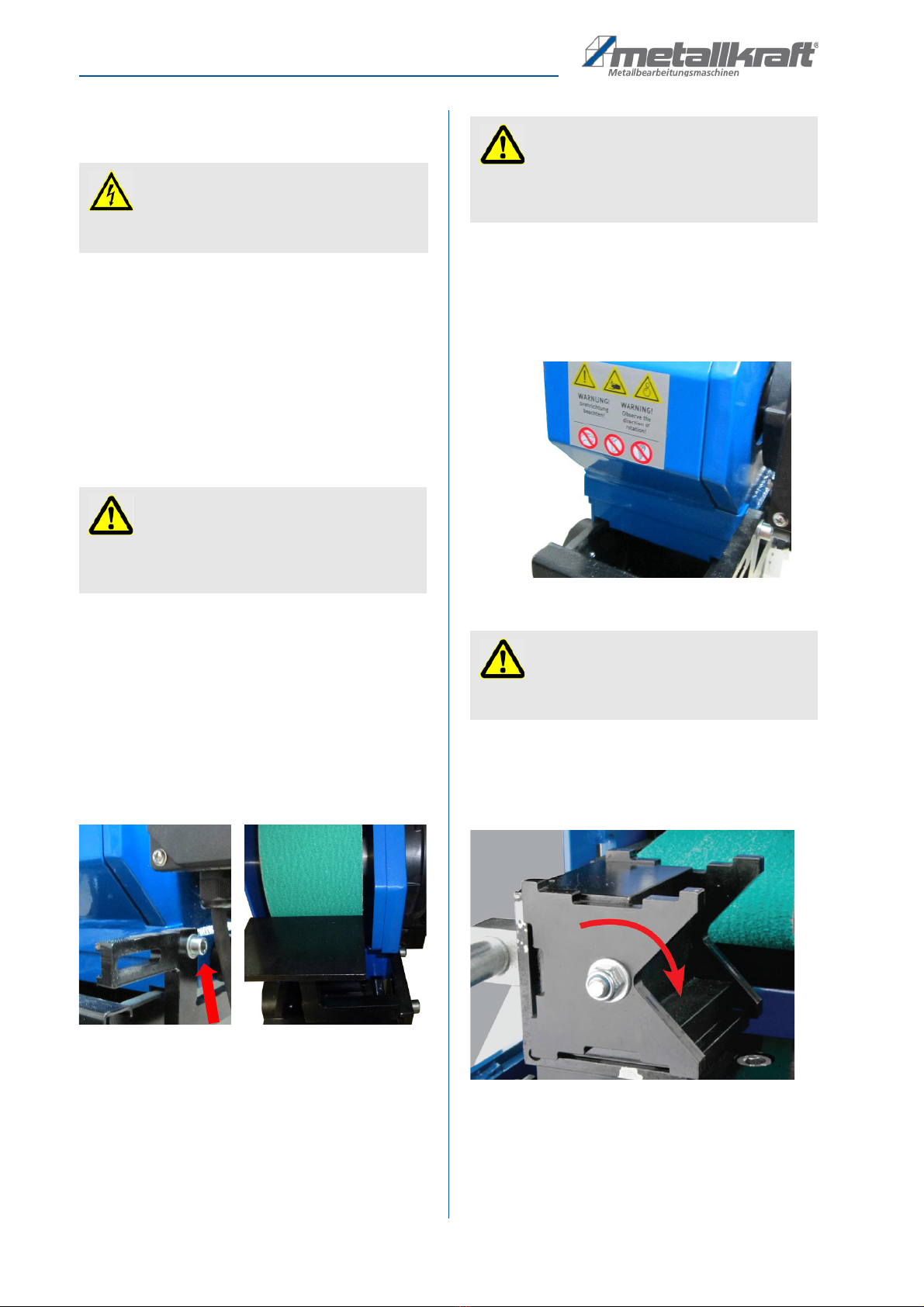
2.6 Safety signs on the machine
The following safety signs and notes are applied on the
Combined pipe, section and belt grinding Machine (Fig.
1), which need to be observed and followed.
Fig. 1: Safety signs
Eye protection
The protective goggles protect the eyes against parts
flying off and splashes of liquids.
Ear protection
The hearing protection protects the ears against
damages of hearing due to noise.
Breathing protection
The breathing protection serves for protecting the
respiratory passages and the lung against the intake
of dust particles.
Protective gloves
The protective gloves serve to protect the hands
against sharp components as well as against fric-
tion, abrasions or deep injuries.
Safety boots
The safety boots protect the feet against crushes,
falling parts and slipping over on slippery under-
ground.
Protective clothes
The protective clothes are tight clothes of little ten-
sile strength.
12
3
5
4

6 KRBS 101 | Version 1.03
Intended use
Damaged or missing safety symbols at the machine may
lead to errors with personal and material damages. The
safety symbols which are applied on the machine must
not be removed. Damaged safety symbols must be re-
placed immediately.
The machine must be put out of operation from the mo-
ment when the labels are unable to be recognized and
understood at first glance, until new labels are attached.
3 Intended use
The pipe belt sander is designed exclusively for grinding
and deburring of various metallic, cold and non-combus-
tible materials. It must not be operated in potentially ex-
plosive environments.
For operation at the pipe grinding station on the front of
the device, the workpiece must be tightened with the ex-
isting vise.
For operation on the belt grinding station on the back of
the device, the supplied support table must be mounted
before machining the workpiece.
When working on the various workstations, attention
must be paid to the respective direction of rotation of the
sanding belt (indicated by means of directional arrows at
the respective workstations). The direction of rotation
must be determined by means of a grinding test (eg
sparking of a test piece).
Proper use also includes compliance with all information
in this manual. Any use beyond the intended use or oth-
erwise is considered misuse.
Misuse:
The Pipe belt sander must neither be used for grinding
flammable materials (e. g. magnesium, wood or similar).
The company St rmer Maschinen GmbH is not liable for
any design and technical modifications on the the Ma-
chine.
Any claims due to damages because of intended use are
excluded.
4 Technical Data
4.1 Table
4.2 Type Plate
Fig. 2: Type Plate KRBS 101
5 Transport, packaging, storage
5.1 Delivery and transport
Delivery
Check if there are any visible transportation damages af-
ter delivery of the Machine. If the Machine shows any
damages, immediately inform the carrier or the distribu-
tor.
WARNING!
Danger in case of misuse!
A misuse of the Machine can result in dangerous sit-
uations.
- Only operate the Machine in the power range given
in the technical specifications.
- Never bypass or override the safety devices.
- Only operate the Machine in a technically flawless
status.
Technical Data Model KRBS 101
Belt dimensions 100 x 2000 mm
Motor output 2.5 kW/3.3 kW
Electrical connection 400 V/50 Hz
Motor speed 1400/2800 rpm
Belt speed 15–30 m/s
Grindable diameter 20 - 76 mm
Adjustable grinding angle 30 - 90° (0° - 60°)
Extraction duct nominal
width outside
2 x 74 mm
Dimensions L x W x H 1250 x 750 x 1140
mm
Weight 159 kg

Description of the device
KRBS 101 | Version 1.03 7
Transport
The device may only be transported upright and only
when the engine is switched off.
Transport with a forklift / pallet truck:
For shipment, the unit is delivered in a box on a pallet so
that it can be transported by forklift or pallet truck.
Transport by Crane:
The machine has a special transport eyelet. Always use
a crane when assembling and transporting the machine
and only hang the hoists in the lifting lug.
5.2 Packaging
All packaging materials and packaging aids used in the
device are recyclable and must always be recycled.
Packaging components made of cardboard are crushed
to give waste paper collection.
The foils are made of polyethylene (PE) and the uphol-
stery parts made of polystyrene (PS). These substances
must be handed over to a recycling center or to the re-
sponsible disposal company.
5.3 Storage
The Machine must be stored thoroughly cleaned in a dry,
clean and frost-free environment.
6 Description of the device
6.1 Image
The illustrations in these operating instructions
serve the general comprehension and may deviate
from the actual type.
Fig. 3: Description of the device
1 Cover for surface grinding station
2 Feed grinding
3 Cover belt grinding station
4 Cover grinding belt
5 Suction
6 Emergency stop button
7 Speed stage switch
8 Changeover switch pipe grinder L - belt sander R
WARNING!
Danger to life due to falling load!
If the weight of the equipment and the permissible lift-
ing capacity of the lifting equipment are not observed
during transport or lifting operations, the machine
may tip over or crash.
- During transport and during lifting work, pay atten-
tion to the weight of the device and the permissible
load capacity of the lifting equipment.
NOTE !
Protect the Machine against humidity.

8 KRBS 101 | Version 1.03
Installation
9 Drilling holes for anchoring
10 Clamping lever for height adjustment
11 Handwheel for adjusting the belt tension
12 Adjustment screw for height of the roller
13 Jaw
14 Clamping lever for clamping jaw
15 Guide cross slide
16 Feed lever
17 Clamping lever for cross slide
18 Grinding angle adjustment
19 Clamping prism
20 Cover tube grinding station
21 Transport lug
22 Adjustment screw
23 Contact rollers
24 START- and STOP Button
25 Workpiece stop
26 Internal hex
6.2 Scope of supply
- 1x Standard-grinding belt 36 grain
- 1x Spanner
- 2x Swarf catchment containers
- 1x Grinding roll Ø 42mm
6.3 Accessories
- Roller for 3/8“ pipe
- Roller for 1/2“ pipe
- Roller for 22 mm pipe
- Roller for 3/4“ pipe
- Roller for 28 mm pipe
- Roller for 1“ pipe
- Roller for 34 mm pipe
- Roller for 1 1/4“ pipe
- Roller for 44 mm pipe
- Roller for 1 1/2“ pipe
- Roller for 50 mm pipe
- Roller for 2“ pipe
- Roller for 62 mm pipe
- Roller for 2 1/2“ pipe
- Roller for 28 mm pipe
- Extraction unit (optional)
7 Installation
In order to attain good functionality as well as a long du-
rability of the Machine the installation site should fulfil
certain criteria.
- The Machine may only be placed and operated in a
dry, venti lated space.
- Do not place the machine in the neighbourhood of
dust- and chips producing machines.
- The place of erection should be free of vibrations,
so away from presses, planers etc.
- The floor hast to be suitable for the work. Pay at-
tention to bearing capacity and levelness of the
floor.
- Protruding parts, like f.i. stop plate grips etc. need
to be made safe in such away that people are not
jeopardized.
- there should be enough place for operation staff
and transport of material.
- Think also of the accessibility for adjustment and
maintenance work.
- Take care of sufficient light (minimal 300 Lux)
ATTENTION!
Check the floor loading capacity before you install
the machine. The place of installation must be capa-
ble of bearing the weight of the machine and the
workpieces.

Installation
KRBS 101 | Version 1.03 9
7.1 Mounting
Fig. 4: Mounting
Step 1: Tighten the machine foot with the four screws on
the ground plate.
Step 2: Lift the machine chassis on the foot. Put an inter-
mediate plate between the pipe notcher and the
foot, before you put him down clefinitely. We acl-
vise you to use a crane. Attention: To litt the
chassis, use the transport eye.
Step 3: Put both screws in and tighten them.
Step 4: Connect the engine cable with the main connec-
tion cable in the chassis.
Fig. 5: Connection of the engine
Step 5: Screw on the feed lever
7.2 Set up
The four mounting points of the machine should be mar-
ked and bare holes should be made for anchorages. The
machine should be rnounted with steel bolts to the floor.
Installation Site
The machine must be set up and operated in a dry, frost-
free and well-ventilated working space. The substrate
must be stable and level, able to support the weight of
the machine and the stresses caused by the operation of
the machine. It must be paid attention to good lighting.
ATTENTION!
The electrical connection of the engine cable has to
be done by an electircan.
NOTE!
After the erection take away the lubrication of the
white rnetal parts, which has been put there for rea-
sons ot protection.
- Use for this the usual solvents
- No water, no nitrosolvents etc.!
10 KRBS 101 | Version 1.03
Assembly
7.3 Electrical connection
You should pay attention that:
- The connection has the same marks (voltage, sup-
ply frequency. phases) as the engine.
- The voltage of 400 V (16A fuse) has to be used.
The plug will be connected to the cables L 1, L2, L3, PE.
Eventually you can operate this machine to with a fixed
connection.
8 Assembly
8.1 Belt sander on the back of the de-
vice
Step 1: Pull out the plug.
Step 2: Take out the safety screw and open the cover.
Fig. 6: Adjust the work surface
Step 3: Screw the working surface to the device side with
two Allen screws.
Step 4: Adjust the position of the work surface after loos-
ening the fixing screws on the side of the unit
and then tighten the screws. The distance of the
work surface to the sanding belt may be max. 2
mm.
Step 5: After completion of the work on the rear work sur-
face, the cover must be closed. To do this, fold
down the work surface after loosening the fixing
screws or remove it.
Then close the cover and tighten the fixing
screw.
Fig. 7: Cover on the back of the Machine
8.2 Pipe grinder on the front of the device
Adjust clamping prism
Fig. 8: Prism
The clamping prism has 4 different shots for clamping
different profiles and tubes on the four sides. Depending
on the shape of the workpiece, the most suitable recep-
tacle can be selected and mounted.
DANGER!
Danger by voltage!
Danger by voltage! Working on the electrical connec-
tion may only be done by electricians
ATTENTION!
After connecting the plug. you have to check the run-
ning direction of the engine. Should this be wrong,
you have to change the two phases.
DANGER!
Risk of injury!
Never reach into the gap between the roller and the
housing when the machine is connected to the power
supply!
DANGER!
Risk of injury!
If you do not work at the rear grinding position, the
sanding belt cover must always remain closed!

Assembly
KRBS 101 | Version 1.03 11
Step 1: Loosen the nut on the front of the tension prism
and turn the tension prism so that the desired lo-
cation is on the right side opposite the jaw.
Attention: Both areas of the clamping prism must
always be in the same position!
Fig. 9: Applications
Adjust workpiece angle
The angle of attack of the tool on the sanding belt can be
adjusted with the angle adjustment device in the range of
90 ° (straight workpiece position) to 30 °.
Fig. 10: Adjust workpiece angle
Step 1:To adjust the workpiece angle, loosen the clamp
screw on the angle fixture, turn the workpiece fix-
ture to the desired angle using the scale, and
tighten the clamp screw again.
Adjust feed travel
For the feed travel can be selected from 2 different travel
limits. For this purpose, the feed lever must be screwed
to either the front (A, Fig. 11) or the rear hole (B) at the
bottom of the pipe grinder working position.
Fig. 11: Feed travel
Adjust workpiece stop
In order to process several identical workpieces in the
same way, it is advisable to set a uniform position of the
workpieces in the clamping prism. This is done with the
help of the workpiece stop.
Fig. 12: Workpiece stop
Step 1: Release the clamping lever and move the work-
piece stop to the desired position.
Step 2: Tighten the clamping lever and clamp the work-
piece in the clamping prism. Move the workpiece
stop to the desired position.
Step 3: Fold out the workpiece stop and machine the
workpiece.
Step 4: To process the next workpiece, fold in the work-
piece stop and position the workpiece against
the stop.
A
B

12 KRBS 101 | Version 1.03
Operation
Pipe sander cover
The cover at the pipe grinder working position protects
the operator from workpiece swarf and dust as well as
sparks. The cover must always be mounted and lowered
while the machine is in operation. Due to the transparent
material, the machining process can be well monitored
and controlled.
Fig. 13: Cover
Height adjustment of the contact roller
Fig. 14: Height adjustment
Step 1: Disconnect the power plug.
Step 2: Loosen the two clamping levers R (Fig. 14).
Step 3: Adjust the height of the contact roller with the ad-
justing screw S (Fig. 14). When lowering the con-
tact roller, if necessary, press it down with your
hand. The position of the contact roller (-20 mm -
0 mm - +20 mm) can be read on the scale.
Step 4: Tighten the two clamping levers R.
8.3 Surface grinding station
Step 1: Disconnect the power plug.
Step 2: Open the cover on the upper side of the device
Fig. 15: Surface grinding station
The workpiece must be stopped for processing at the
stop in the running direction of the belt (Fig. 15).
9 Operation
Fig. 16: Never reach into the openings on the Machine
DANGER!
Risk of injury!
The pipe grinder cover must always be folded down
while machining a workpiece!
WARNING!
Danger to life!
There is danger to life for the operator and for other
persons if they do not comply with the following rules.
- The operator must not work if he is under the influ-
ence of alcohol, drugs or medication.
- The operator must not work if he is overworked or
suffers from fatigue and difficulties in concentrating.
- The Machine may only be operated by one person.
Other persons must not enter the working area dur-
ing operation.
Operation
KRBS 101 | Version 1.03 13
Step 1: Check mains plug and cable prior to start of
work.
Step 2: Check whether the workpiece support tables are
firmly tightened.
Step 3: Check whether the correct grinding belt with the
correct grain size is installed.
9.1 Working position pipe grinder
Step 4: Adjust the clamping prism to the workpiece to
be clamped. V-prism for round tubes, stepped
prism for flat and square material.
Step 5: If necessary, adjust the desired grinding angle
via the angle setting. To do this, loosen the Al-
len screw and turn the workpiece clamping
device to the desired degree. After adjust-
ment, tighten the screw again.
Step 6: Depending on the desired feed travel, screw the
feed lever to the appropriate position.
Step 7: If several workpieces with the same dimensions
are to be machined, it is recommended to work
with the workpiece stop.
Step 8: Clamp the workpiece. To do this, place the
workpiece in the clamping prism, push the
clamping block against the material and pull the
clamping lever backwards.
Step 9: Move the carriage transversely until the sanding
belt reaches the entire machining width on the
workpiece. Lock the carriage after setting with
the clamping lever.
Step 10: Check whether the center of the workpiece
matches the center of the roller. If this is not the
case or if a special application is desired, adjust
the height of the contact roller.
Step 11: Set the desired belt speed
Step 12: Select the desired operating mode:
L for pipe grinder (L for surface grinder, R for
belt grinder).
Fig. 17: Operating modes: pipe grinder L , belt grinder R
Step 13: Start the extraction system.
Step 14: Start the sanding belt motor by pressing the
green Start Button.
DANGER!
Danger of injury!
Never put your hands into any openings (e. g.
between grinding belt and housing) of the machine,
as long as it is connected to the mains!
DANGER!
Danger of injury!
During all works with the grinding machine
- well-fitting clothing must be worn.
- no jewellery must be worn.
- no scarfs, ties or similar must be worn.
- in case of long hair, a hairnet must be worn.
Use ear protection!
Use protective glasses!
Use breathing protection!
Use protective gloves!
Use protective boots!
Wear protective clothes!
NOTE!
The belt speed can be changed as required during
the operation of the machine in the preselected direc-
tion of rotation.
DANGER!
Before changing the operation mode pipe grinder or
belt sander the engine must be switched off or stand
still. If the operating mode or direction of rotation is
switched while the engine is running, the machine
shuts off automatically.

14 KRBS 101 | Version 1.03
Operation
Fig. 18: Check the direction of rotation
Step 15: Check the direction of rotation of the grinding
station. The direction of rotation of the sanding
belt must match the corresponding direction of
rotation arrow after selecting the sanding sta-
tion.
Step 16: Fold down the pipe grinder protective cover.
Step 17: Start the grinding process. To do this, push the
clamped workpiece forward against the sand-
ing belt with the feed lever (16, Fig. 3).
Step 18: When the correct radius has been ground, re-
move the tube from the clamp and remove the
outer ridge with the face grinding surface (2).
9.2 Working position belt sander
Step 4: Open the cover on the back of the device. To do
this, unscrew the hexagon socket screw (Fig.
19 left, arrow) and open the cover upwards.
Fig. 19: Open the Cover
Step 5: Screw the work surface with two hexagon socket
screws on the side of the unit and align. The dis-
tance of the work surface to the sanding belt may
be max. 2 mm.
Step 6: Select the desired operating mode:
R for belt sander (L for pipe grinder, L for sur-
face grinder).
Step 7: Start the extraction system.
Step 8: Start the sanding belt motor by pressing the
green START button.
Fig. 20: Check the direction of rotation
Step 9: Check the direction of rotation of the grinding
station. The direction of rotation of the sanding
belt must match the corresponding direction of
rotation arrow after selecting the sanding sta-
tion.
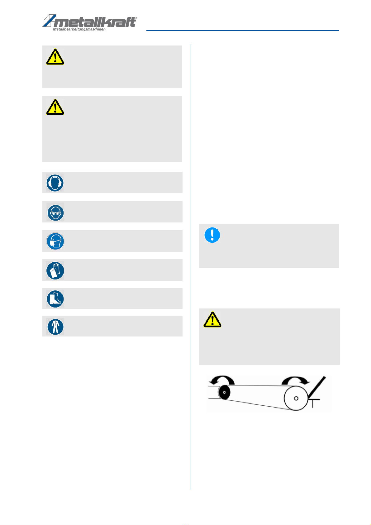
Fig. 21: Flying sparks
Step 10: Start the grinding process. To do this, stop the
workpiece at the work table and guide it against
the sanding belt.
Step 11: If machining of the workpiece on the belt sander
is complete, deburr the workpiece with the sur-
face grinding surface (2, Fig. 3) if necessary.
ATTENTION!
If the sanding belt is turned in the correct direction,
the sparks must be directed downwards! (Fig. 21)
DANGER!
Danger of injury!
Never reach into the gap between the roller and the
housing when the machine is connected to the power
supply!
ATTENTION!
If the sanding belt is turned in the correct direction,
the sparks must be directed downwards! (Fig. 21)

Care maintenance and overhaul/repair
KRBS 101 | Version 1.03 15
Step 12: After completion of the work on the belt grinding
station, the cover must be closed. To do this,
fold down the work surface after loosening the
fixing screws or remove it.
Then close the cover and tighten the fixing
screw.
9.3 Working position surface grinder
Step 4: Open the cover on the upper side of the device.
Fig. 22: Surface grinding station
Step 5. Check the running direction of the sanding belt.
Step 6. Stop the workpiece at the stop in the running di-
rection of the belt and guide it against the sand-
ing belt for processing.
9.4 Shut down the Machine
Step 1: To switch off the Machine, press the red STOP
Button.
Step 2: Switch off the extraction system.
Step 3: Pull the mains plug of the grinding Machine.
10 Care, maintenance and overhaul/re-
pair
Tips and recommendations
In order that the Machine is always in good operat-
ing status, it is necessary to regularly perform care
and maintenance works.
WARNING!
Danger in case of insufficient quali-
fication of the staff!
Insufficiently qualified persons cannot estimate the
risks while performing repair work at the Machine
and expose themselves and others to the danger of
severe injuries.
Have all maintenance works only performed by quali-
fied persons.
DANGER!
Electric shock is life-threatening!
There is a danger of life in case of contact with cur-
rent running through components.
- Always disconnect the mains plug before you start
cleaning and maintenance works.
- Connections and repairs of the electrical equipment
may only be carried out by specialized electrical
staff.
NOTE!
After maintenance, repair and cleaning works, check
if all claddings and protective equipment are prop-
erly reassembled to the machine and that there are
no more tools inside or in the working area of the
Machine.
Damaged protection devices and machine parts must
be properly repaired or replaced by an acknowledged
specialist workshop.

16 KRBS 101 | Version 1.03
Care maintenance and overhaul/repair
10.1 Cleaning and lubrication of the machine
.
The Machine should generally be cleaned after every
use.
Regularly remove the spark arrester and check whether
the interior of the grinding machine must be cleaned.
Brush or wipe all open machine parts in regular intervals
using a broom or a cloth.
Treat blank metallic working surfaces with anti-rust
spray.
Lubricate all moving parts and bearings once per month.
If necessary, replace the graphite support at the level
grinding area.
10.2 Adjust Belt change and Belt run
Step 1: Switch off the machine witt1 the main switch and
unplug the machine.
Step 2: Unscrew the safety screw and open Hie side
coverings plate by turning the lever.
Step 3: Turn the cover of the abrasive wheel (2, Fig. 3)
backwards.
Step 4: Release the bell by turning the hand wheel
(11, Fig. 3).
Step 5: Take out the belt.
Step 6: Put in a new belt.
Step 7: Stretch the belt wilh lhe hand wheel. You have
reached lhe right bell tension if the upper spin-
clle nul is culs out 7 lo 10 mm and the lension is
taken over by the spring only.
Step 8: Afterwareis close lhe cover ancl lighlen the
safety screw again.
Step 9: lt is recommended, to adjust the band running a
bit rough by pushing the belt to the abrasive
wheel and turning the acljustment screw .
Step 10: Close the cover of lhe abrasive wheel and start
the machine.
Step 11: The bell running can now be adjusled by lurning
the acljuslmenl screw. Turn care fully ancl
watch how the bell is cloing. lf you have rea-
ched lhe right adjustmenl, you should be see-
ing lhe same distance on both sicles on lhe
grincling roller.
10.3 Changing the contact roller
Step 1: Disconnect the power plug.
Step 2: Unscrew the safety screw and open the side
cover.
Step 3: Relax the sanding belt by turning the hand-
wheel. Then open the cover of the surface
grinding surface .
Step 4: Remove the sanding belt.
Step 5: Remove the contact roll.
ATTENTION!
- It is indispensable to switch the machine off and to
pull off the mains plug before performing cleaning
and maintenance work!
- Never use solvents or cleaning solutions to clean
plastic parts or lacquered surfaces. The surface may
be dissolved and consequential damage may occur.
ATTENTION!
- Never remove chips or grinding dust with bare
hands. Danger of injuries due to sharp-edged chips.
- Never remove chips or grinding dust with a com-
pressed air blow gun. This can lead to eye injury
and may damage machine parts.
ATTENTION!
Use only belts with the dimension 2000 mm x 100
mm. Check before installation for your own safety
tl1e dimensions of the belt and check it for evt.
structural faults. Always select that belt which suits to
the material to be grinded.
Choose grinding belts with a weid where the opposite
ends are glued together. Grinding belts with the ends
glued together on top, can break when changing the
belt direction.
WARNING!
When changing the sanding belt, the upper limbs between
the drive roller and the sanding belt can be crushed.
WARNING!
Danger of Electric shock!
Disconnect the mains plug before working on the
device.

Care maintenance and overhaul/repair
KRBS 101 | Version 1.03 17
Step 6: Clean the contact surfaces and the receptacle on
the contact roller holder.
Step 7: Insert the new contact roller into the contact roller
holder
Step 8: Apply the sanding belt.
Step 9: Tighten the sanding belt (observe clearance of 7
- 10 mm) and adjust the belt run..
10.4 Troubleshooting
Tension
ATTENTION!
lf one of the following faults takes place, stop the
machine at once. Before searching for lhe mistakes,
switch off and unplug the machine. All repairs ancl
changes may only be clone by qualified ancl trained
staff.
NOTE!
Contact your neared Metallkraft dealer if you are una-
ble to solve the problems with your machine. Please
take the following information from the machine or
from the operating manual so that we can help you in
the best possible way.
- Machine model
- Serial number of the machine
- Year of manufacture
- Exact error description
Fault Possible cause Solution
The machine doesn’t work. 1. The mains plug is not connected
to the power socket.
2. Supply cables defective.
3. Switch defective.
4. Motor defective.
1. Connect the mains plug.
2. Call a service engineer.
3. Call a service engineer.
4. Call a service engineer.
The belt is not running centrically. 1. The belt operation is not adjusted.
2. Bearing damage in the contact
roll.
1. Adjust the belt operation.
2. Remove the contact roll.
The belt contacts the housing at the
level grinding area.
1. The graphite layer is worn. 1. Replace the graphite layer.
Poor grinding result. 1. Wrong grinding belt.
2. Worn grinding belt.
1. Install the correct grinding belt.
2. Change the grinding belt.

18 KRBS 101 | Version 1.03
Disposal recycling of used devices
11 Disposal, recycling of used devices
For environmental benefits it is necessary to ensure that
all components of the machine are only disposed of by
the provided and allowed means.
11.1 Decommissioning
Immediately decommission used machines in order to
avoid later misuse and endangering of the environment
or of persons.
- Dispose of all environmentally hazardous operating
materials of the used device.
- If required, disassemble the machine into easy-to-han-
dle and usable components and parts.
- Supply the machine components and operating materi-
als to the provided disposal routes.
11.2 Disposal of electrical devices
Electrical devices include numerous recyclable materials
as well as environmentally hazardous components.
These components must be disposed of separately and
professionally. In case of doubt, please contact your mu-
nicipal waste management company.
For the recycling process, please request the assistance
of a specialized waste disposal centre if required.
11.3 Disposal of lubricants
The manufacturer of the lubricant makes the disposal in-
structions for the used lubricants available. If applicable,
ask for the product-specific data sheets.
12 Spare parts
12.1 Ordering spare parts
The spare parts may be purchased with the authorised
dealer or directly with the manufacturer. Please find the
corresponding contact data in Chapter 1.2 Customer
service.
Indicate the following basic information for spare part or-
ders:
- Type of device
- Serial number
- Quantity
- Designation
- Required mode of dispatch (mail, freight, sea, air,
express)
- Address of dispatch
Spare part orders which do not include the above indica-
tions may not be taken into consideration. If the indica-
tions regarding the mode of dispatch are missing, the
product is dispatched at the discretion of the supplier.
Example
The contact roller for the Combined pipe, section and
belt grinding machine KRBS 101 must be ordered. The
contact roller has the number 218 in the spare parts
drawing 2.
By ordering spare parts, send a copy of the spare parts
drawing (2) with the marked part (contact roller) and
marked positon number (218) to the dealer or spare
parts department and provide the following information:
- Type of device: Combined pipe section and belt
grinding machine KRBS-101
- Item number: 3921001
- Drawing number: 2
- Position nummer: 218
Item number of your device:
Combined pipe, section and belt grinding machine KRBS 101:
3921001
NOTE!
The manufacturer's warranty will become null and
void if non admitted spare parts are being used
DANGER!
Danger of injury by the use of
wrong spare parts!
Dangers may result for the user and damages as well
as malfunctions may be caused by using wrong or
damaged spare parts.
- Only use original spare parts of the manufacturer or
spare parts admitted by the manufacturer.
- Always contact the manufacturer in case of uncer-
tainties.

Spare parts
KRBS 101 | Version 1.03 19
12.2 Spare parts drawings
In case of service, the following drawings shall help to identify the necessary spare parts. If necessary, send a copy of the
parts drawing with the marked components to your authorised dealer.
Fig. 23: Spare Parts Drawing 1 KRBS 101

20 KRBS 101 | Version 1.03
Spare parts
Fig. 24: Spare Parts Drawing 2 KRBS 101
Table of contents
Other Metallkraft Industrial Equipment manuals


Popular Industrial Equipment manuals by other brands


Eastwood
Eastwood 10049Z operating instructions

Yoshitake
Yoshitake Trap Star TSF-13 manual

SMC Networks
SMC Networks CE Series user manual

OmniCure
OmniCure AC7 Series quick start guide

Ace
Ace SDH38EU Operating and mounting instructions

Graphic Whizard
Graphic Whizard Graphic Whizard GW 6000 instruction manual


