Metasys H1 Installation instructions

Hygienesystem
H1
Gerätedokument
Einbau, Betrieb und Wartung
Hygiene system
H1
Equipment Logbook
Assembly, operation and maintenance
Systeme d’hygiene
H1
Livret d’appareil
Installation, fonctionnement et entretien
Sistema d’igiene
H1
Verbale d’installazione
Montaggio, funzionamento e manutenzione
H
1
1
EN

EN
2
1. Index
The header on each page defines the user group particular information is
aimed at.
Chapter Page
1. Index 2
2. Explanation of the pictograms 2
3. General information 3
4. Product description 4
5. Explanation of the type plate 4
6. Technical data 4
7. Installation requirements 5
8. Modular assembly 6
9. Functional description 7
10. Cleaning cycles 9
11. Hygiene System H1 - maintenance 10
12. Hygiene System H1 - control panel 11
13. Electronic circuit board 12
14. Inspections 14
15. Cleaning and disinfection 14
16. Re lling the H1 cartridge 15
17. Disposal 15
2. Explanation of the pictograms
iInformation
Caution!
General warning sign
Refer to instruction manual/booklet
Index Explanation of the pictograms
Practice personnel, technicians

3
EN
3. General information
The safety, reliability and performance of the appliance is
only guaranteed by METASYS if the following instructions are
observed:
Assembly, alterations or repairs may exclusively be carried out
by authorized service personnel in compliance with EN Standard
60601-1 (International Standard for Medical Electrical Apparatus, in
particular Part 1: General Rules for Safety).
The electrical installation must comply with the regulations of the IEC
(International Commission for Electrical Engineering).
The apparatus must exclusively be used in conformity with the
instructions for installation, operation and maintenance.
Only original parts may be used for repairs or replacements.
All the guidelines provided by the manufacturer on the correct use of
the Hygiene system H1 must be followed.
All inspection and service work must be entered into the device docu-
mentation at the rst pages of this manual
When requested by an authorized engineer, METASYS agrees to make
all documents available for the use of technically qualied service
personnel.
METASYSacceptsnoresponsibility for damagescaused due toexternal
factors, such as wrong installation, improper use of the apparatus or
unauthorized technical intervention.
Users must study equipment and assure themselves of its good
condition before every use.
When the apparatus is dismantled at the end of its service life, it must
be disposed of properly.
General information
Practice personnel, technicians

1
2
2.1 2.5
2.2 2.3 2.4
EN
4
Product description Explanation of the type plate Technical data
Practice personnel, technicians
4. Product description
The Hygiene System H1
1 provides automatic and continuous
cleaning, disinfection, defoaming and deodorisation of the entire suction
system during operation, with integrated selective function of the suction
hoses.
The system can be retrotted with a tube holder for two suction hoses and
two extra retainers with selectable conguration.
5. Explanation of the type plate
2 See illustration
2.1 Serial number
2.2 Address of the manufacturer
2.3 Mains supply data
2.4 Protection class II
2.5 Type BF sign
6. Technical data
Permissible water pressure 2-4 bar (working pressure: 2 bar)
Water connection PU tube, nominal width 2 mm,
external Ø 4 mm
Voltage 24 V AC
max. current consumption 450 mA
Frequency 50/60 Hz
max. power consumption 11 VA
Volume of the H1 cartridge 125 ml (pouch: 500 ml)
Suction system wet or dry vacuum pump
Permissible vacuum 100 mbar - 250 mbar
Dimensions (H x W x D)
128 x 132 x 95 mm
(excl. housing and suction tube
holder)
Space requirements (H x W x D)
180 x 260 x 110 mm
(excl. housing and suction tube
holder)
3
4
3.1
3.3
3.1
3.5
3.6
3.2
3.4
3.8
3.9
3.7
5
EN
Installation requirements
Practice personnel, technicians
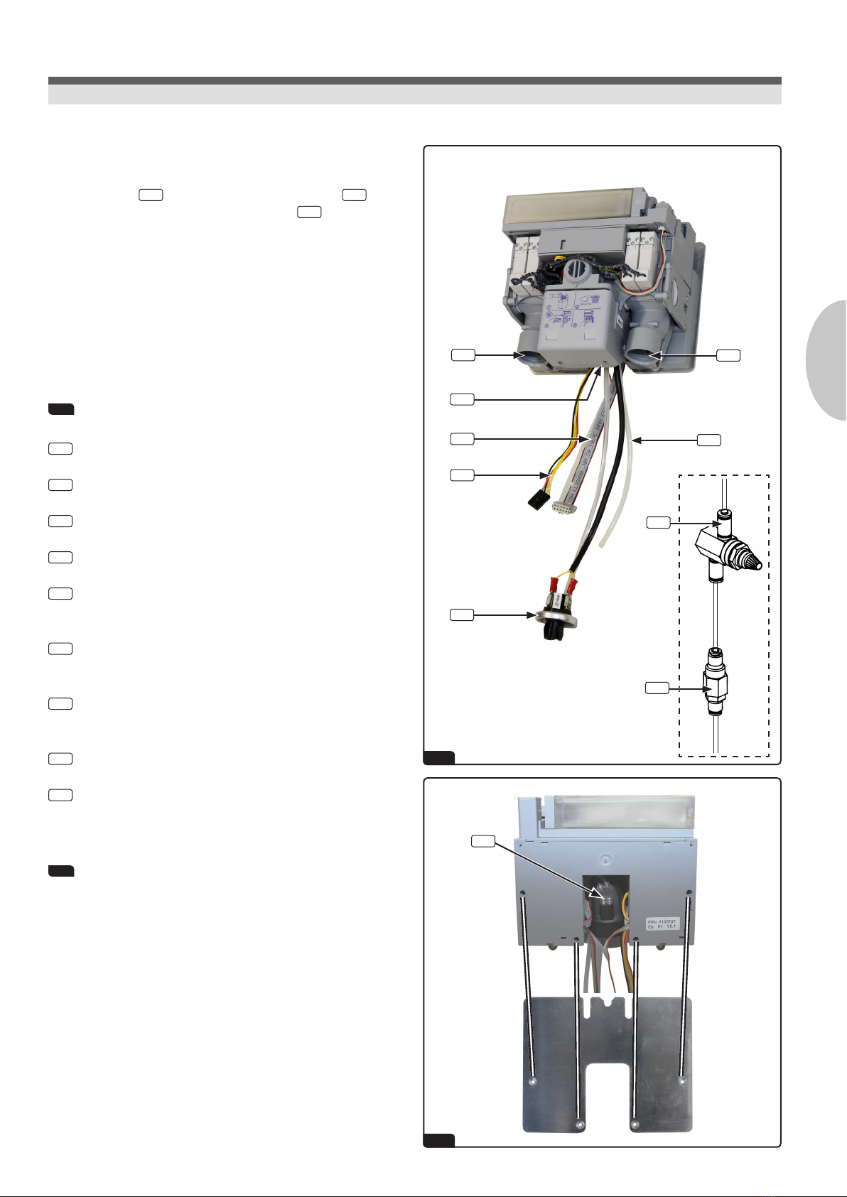
7. Installation requirements
A water lter 3.9 (40 µm) and a pressure regulator 3.8 (2 bar)
must be attached to the mains water supply 3.7 (included in the
scope of delivery).
The underpressure may not exceed 250 mbar at the cannula.
Voltage to terminal X2 must be 24 V AC.
The manufacturer‘s regulations regarding the installation of particular
units must be adhered to.
3 See illustration
3.1 Suction line
3.2 Suction hose 1
3.3 Suction hose 2
3.4 Vacuum switch
3.5 Connection cable (4- and 6-pole)
(control unit, support signal)
3.6 Voltage 24 V AC (red/black)
start signal for suction system (yellow)
3.7 Mains water supply
PU tube, nominal width 2 mm, external Ø 4 mm
3.8 Pressure regulator
3.9 Water lter
4 Fastening on the rear, see illustration

5
6
7
8
9
PUSH
LRH2OGREEN&CLEAN H1
4312
EN
6
Modular assembly
Technicians
8. Modular assembly
To ensure maximum serviceability and to allow variations in assembly, the
Hygiene System H1 consists of ve modules:
5 Module 1: H1 cartridge &adapter plate or connection of pouch
The exchangeable H1 cartridge contains the disinfectant supply for an
approx. 12-15 hours of suction time and is simply slid onto the adapter
plate.
6 Module 2: H1 valve block, double membrane pump &DVGW (air gap)
container
The valve block, in combination with the double membrane pump, is
the heart of the Hygiene System H1. It determines the ratio of water to
disinfectant, dispenses the cleaning agent to the respective handpiece
and controls the elbow closure pieces.
In order to prevent any backow of process water into the drinking water
network, the fresh water is taken from a container with free outlet (per
DVGW).
7 Module 3: Filter housing, elbow closure pieces &suction tubes
The lter housing contains a removable non-drip rake.
The elbow closure pieces (one per suction tube) serve as locking devices
for the suction ow and in order to interrupt the supply of disinfectant if
vacuum pressure drops. They are rotatably hung and form the connection
of the suction tubes which are tted with a thin inner tube that supplies
the cleaning agent to the handpiece. The power of the suction ow can be
adjusted with the regulator on the lter housing.
8 Module 4: Electronic circuit board &housing
The circuit board housing serves as a protection of the electronic circuit
board. This forms the central control unit for the Hygiene System H1.
9 Module 5: Control panel
The control panel displays the main operating states and can be mounted
where desired or as part of the METASYS suction tube holder.
For a more detailed description, refer to page 11.
10
12a 12b
11
H2O
GREEN&CLEAN H1
oH2O IN Suction GREEN&CLEAN H1
Knieverschluss 2
1 2
4
3
6
5
8
9
10
11
7
A
B
C
LRH2O
7
EN
Functional description
Technicians
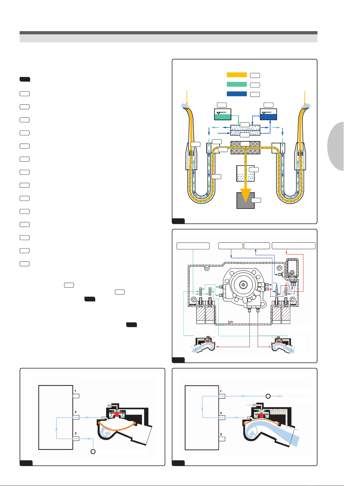
9. Functional description
10 Function diagram, see illustration
ASuction ow
BDisinfectant GREEN&CLEAN H1
CWater
1H1 cartridge or pouch
2DVGW container (water)
3Double membrane pump
4Pump chamber
5Suction ow closure
6Chemical closure
7Filter housing
8Handpiece
9Suction tube with inner tube
10 Amalgam separator or automatic separator
11 Suction system
Lifting the handpiece 8of a suction hose results in a vacuum causing
the respective suction ow sealing membrane 5to be opened by an
associated solenoid valve (L/R) 12a .
The suction ow seal is designed as a pipe elbow and as such it is highly
streamlined and is also insensitive to contaminants 12b . The cleaning
cycles start at the same time as the suction process.
16
13
14
15
EN
8
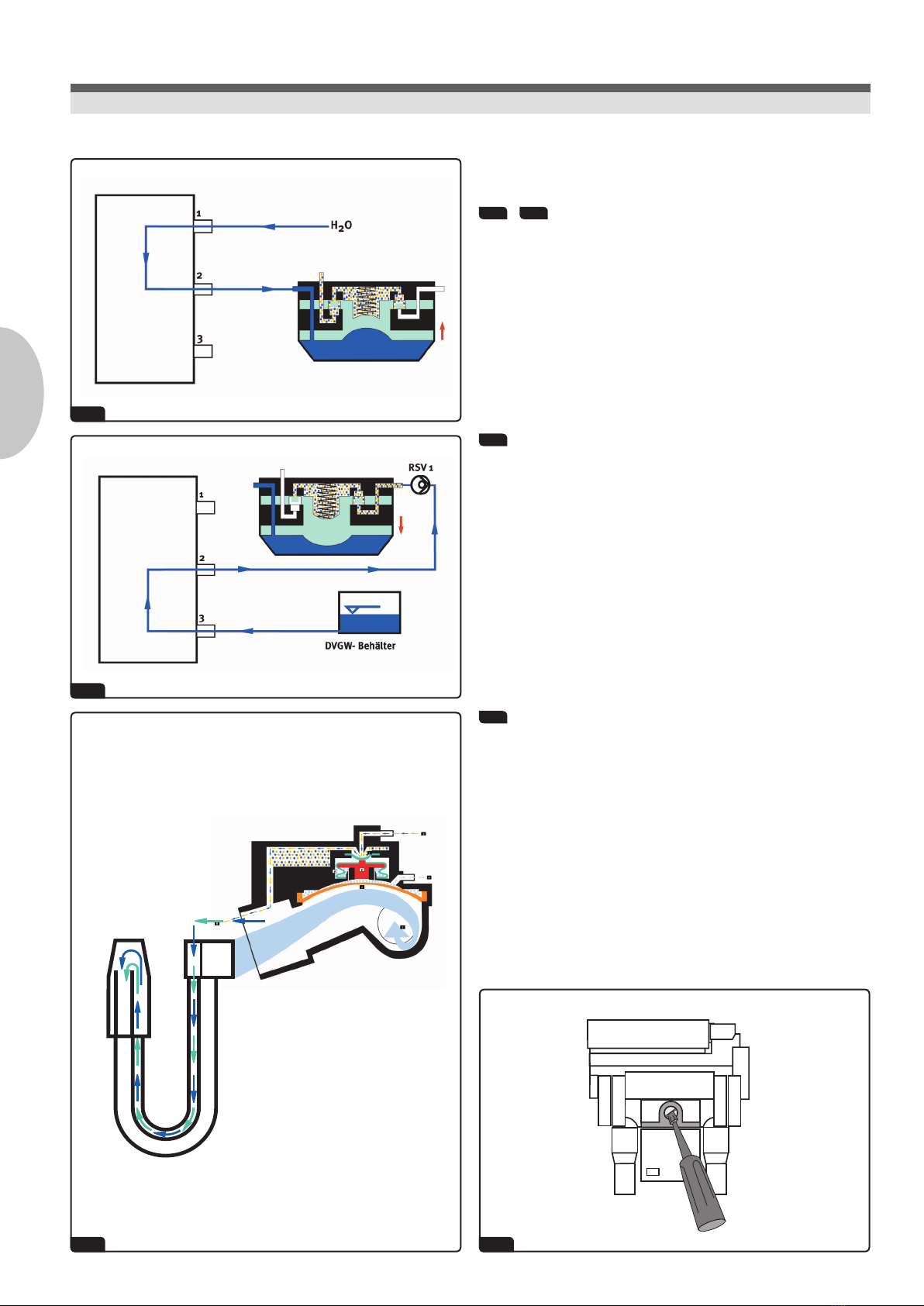
9. Functional description
13 + 14 See illustration
Water is drawn out of the DVGW container, or GREEN&CLEAN H1 is drawn
out of the cartridge or pouch by means of a water pressure-driven
double membrane pump.
15 See illustration
Once drawn off, the disinfectant is pumped through the knee sealing
membrane and through lines in the suction hoses to the handpiece in
use.
The cleaning mixture is then distributed evenly over the inner surface of
the suction tube by the suction ow and thus ensures optimal cleaning
and disinfection of the whole suction system.
16 Adjusting the suction ow rate, see illustration
The suction ow rate can be adjusted by a regulator above the lter cup.
A screwdriver or a coin may be used to adjust the regulator.
Please observe the markings on the regulator!
Functional description
Technicians
17
PUSH
9
EN
10. Cleaning cycles
A cleaning cycle only takes place with suction. As the vacuum decreases,
the ongoing pumping of the cleaning medium is interrupted.
17 Initial cleaning, see illustration
Initial cleaning at the start of each treatment stage. This program is
activated by switching on the main device switch on the treatment
unit. The increased disinfectant dosing creates the ideal starting
prerequisites for the pending treatments with respect to defoaming
and blood solution.
The valve sequence (H1 disinfectant) with 10 x H2O or 2 x H1, 10 x H2O
per suction hose is shown ashing on the external display.
Sequence: 10 / 2 / 10 per hose
The program duration is 1 min 5 sec per suction hose.
18 Normal operation
takes place with a raised suction hose
Sequence: 1 x H1 / 413 x H2O / 1 x H1 per hose
This sequence is halted with an interruption to the suction operation
and is continued when the suction operation resumes or starts anew.
19 Special cleaning
The special cleaning program is started by pressing the respective
button on the operating interface.
This program should be used at the end of each treatment day and
after particularly intense loading of the suction system (e.g. after
lengthy surgical procedures).
Sequence: 40 x H2O / 4 x H1 / 8 x H2O per hose
The program duration is 2 min 35 sec per suction hose.
This intensive cleaning rinses any residues or deposits out of suction
system. Problems arising from periods of inactivity (such as evenings or
holidays) are avoided. A nal disinfection is guaranteed.
During these programs the Hygiene System H1 controls the suction
system, which means that the suction tubes must remain in their holders.
Cleaning cycles
Practice personnel, technicians
27
26
24 25
22 23
20 21
EN
10
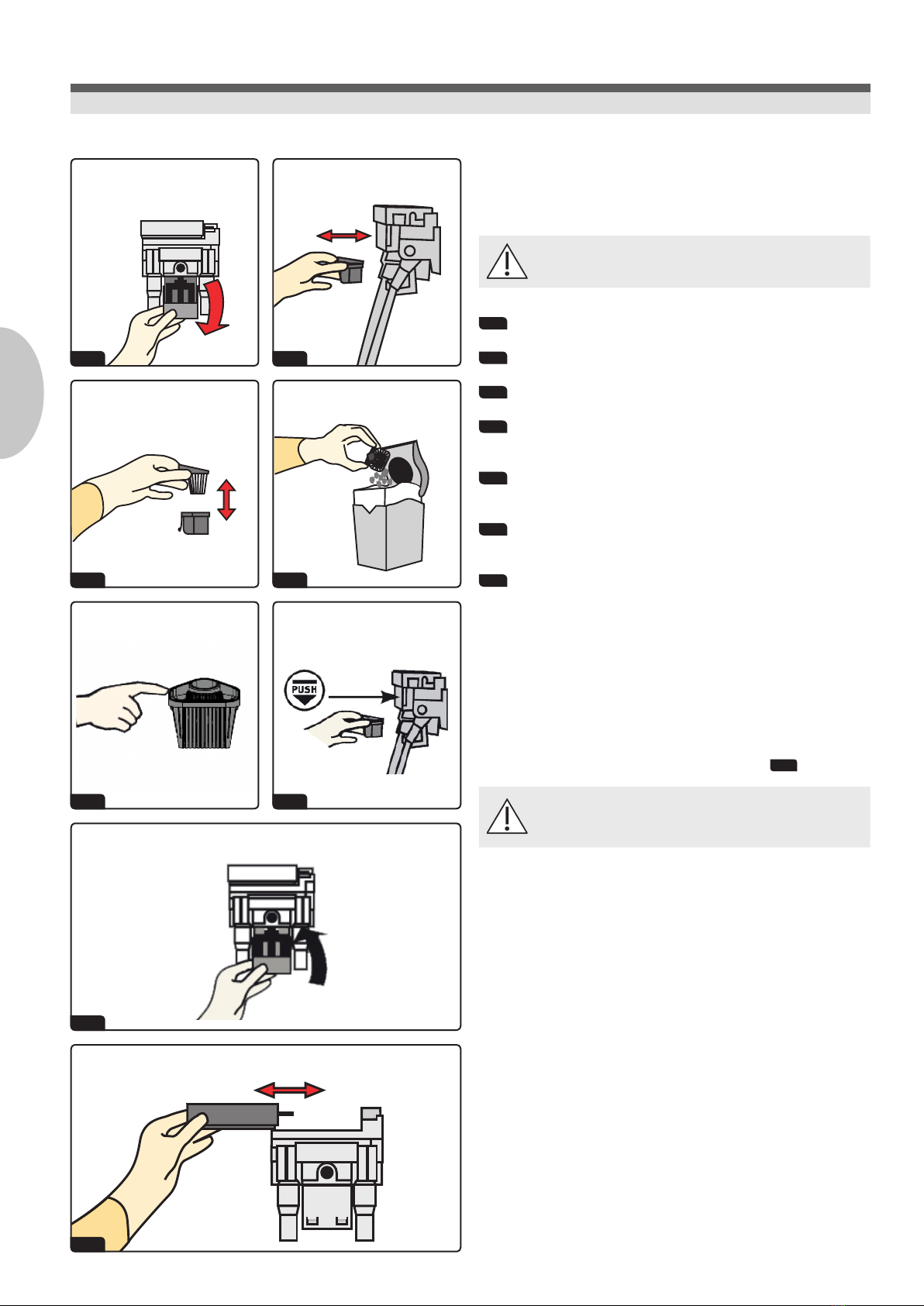
11. Hygiene system H1 - maintenance
Daily cleaning of the lter cup:
Please wear protective gloves when performing this task!
20 Turn down the container clip of the Hygiene System H1.
21 Pull out the lter cup horizontally.
22 Lift out lter rake.
23 Empty the amalgam particles into the designated collection
container (METASYS ECOCEntEr).
24 Clean or replace the lter rakes and grease the sealing lip, if
necessary clean the underside of the housing.
25 Place lter cup with inserted lter rake horizontally back into the
previously cleaned housing.
26 Turn container clip upwards and lock in place.
A change of the lter rake is recommended every 2 to 3 months. The
lter rake must always be in place and the container clip closed when the
suction system is in operation. If the performance of the suction system
declines, check the lter rake for contamination.
Changing the H1 cartridge/pouch (see illustration 27 )
Please also refer to the H1 instructions on the rell package
and on page 11!
If the yellow monitor light no. 2 (empty tank warning) on the control
panel ashes and a short alarm is audible every time the suction tube is
lifted, please exchange the H1 cartridge or renew the pouch as follows:
Removing the H1 cartridge:
Turn off the main switch of the unit.
Press onto the front end of the cartridge briey to release the locking
mechanism (PUSH). The cartridge will slide into a position from which
it can pulled out on its slide rails horizontally.
Inserting the H1 cartridge:
Fit the cartridge in the guide and slide in until it latches in the locking
mechanism.
Turn on the main switch of the unit.
The initial cleaning program starts automatically (duration:
1 min 5 sec/suction hose).
Hygiene system H1 - maintenance
Practice personnel, technicians

28
PUSH
28.328.2
28.1
28.4
11
EN
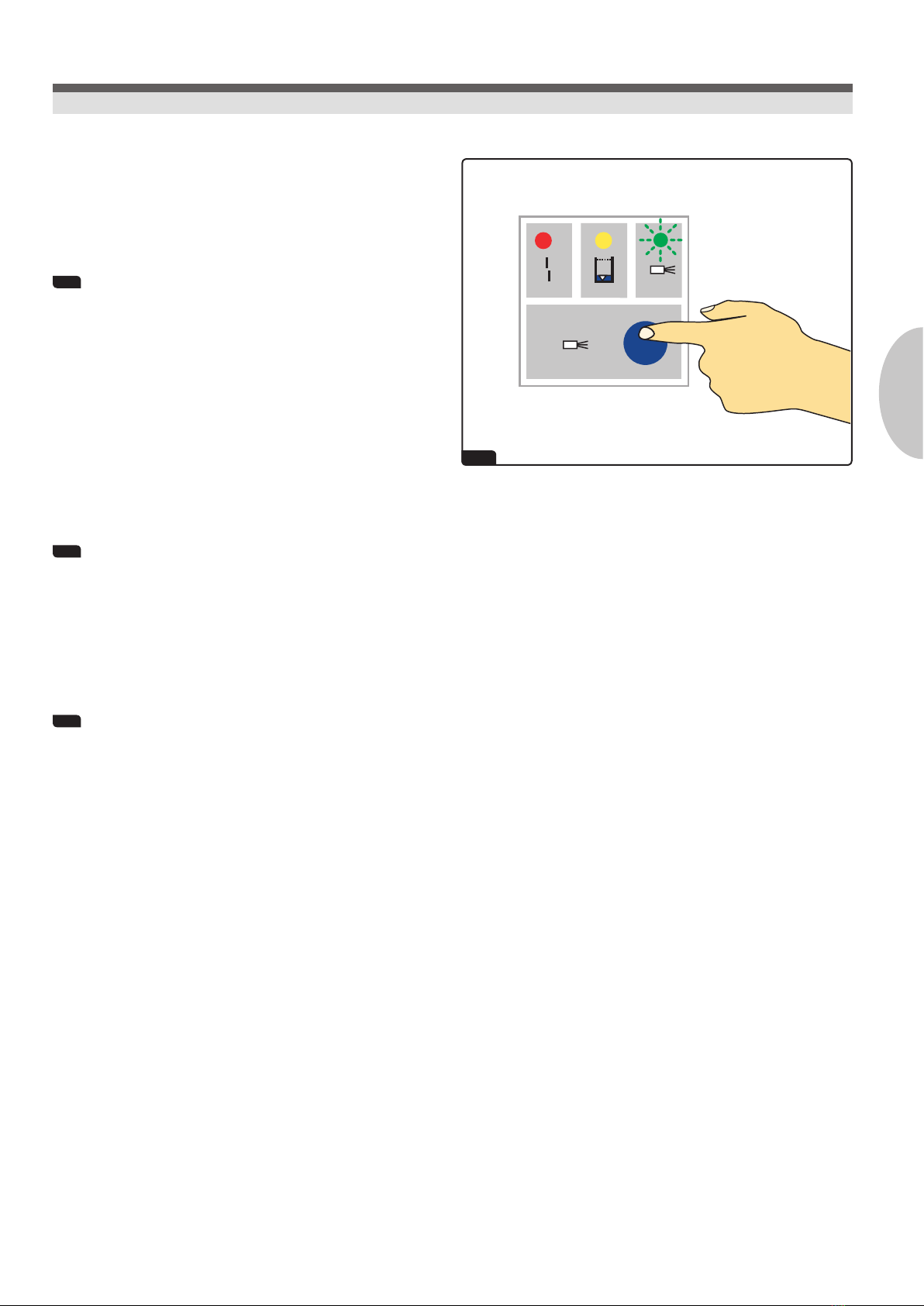
12. Hygiene system H1 - control panel
28 See illustration
28.1 Control light 1 (red): Malfunction
ashing red and 5-times beeping in the event of a fault;
additional short beep each time the suction hose is lifted,
red ashing signal remains; hygiene system not functional,
suction operation still possible:
Membrane break - suctioning functional but no cleaning and
disinfection
red light ashing without signal: Press the PUSH button
once; if this does not work then an electrical fault exists:
Check electronics!
28.2 Control light 2: Empty tank warning
yellow light and single beep whenever the suction tubes are
lifted:
Change the H1 cartridge or H1 pouch!
28.3 Control light 3: Program in use
green light on, suction hose in place:
ready for operation
green light on, suction hose in use:
continuous cleaning in progress
green light ashing slowly (approx. 3 sec):
initial cleaning in progress
green light ashing quickly (approx. 1 sec):
special cleaning in progress
28.4 Start button for special cleaning program
Press PUSH once to activate.
Hygiene system H1 - control panel
Practice personnel, technicians
30
29
29.1
29.2
29.3
29.4
29.5
29.6
29.7
29.8
30
30.6
EN
12
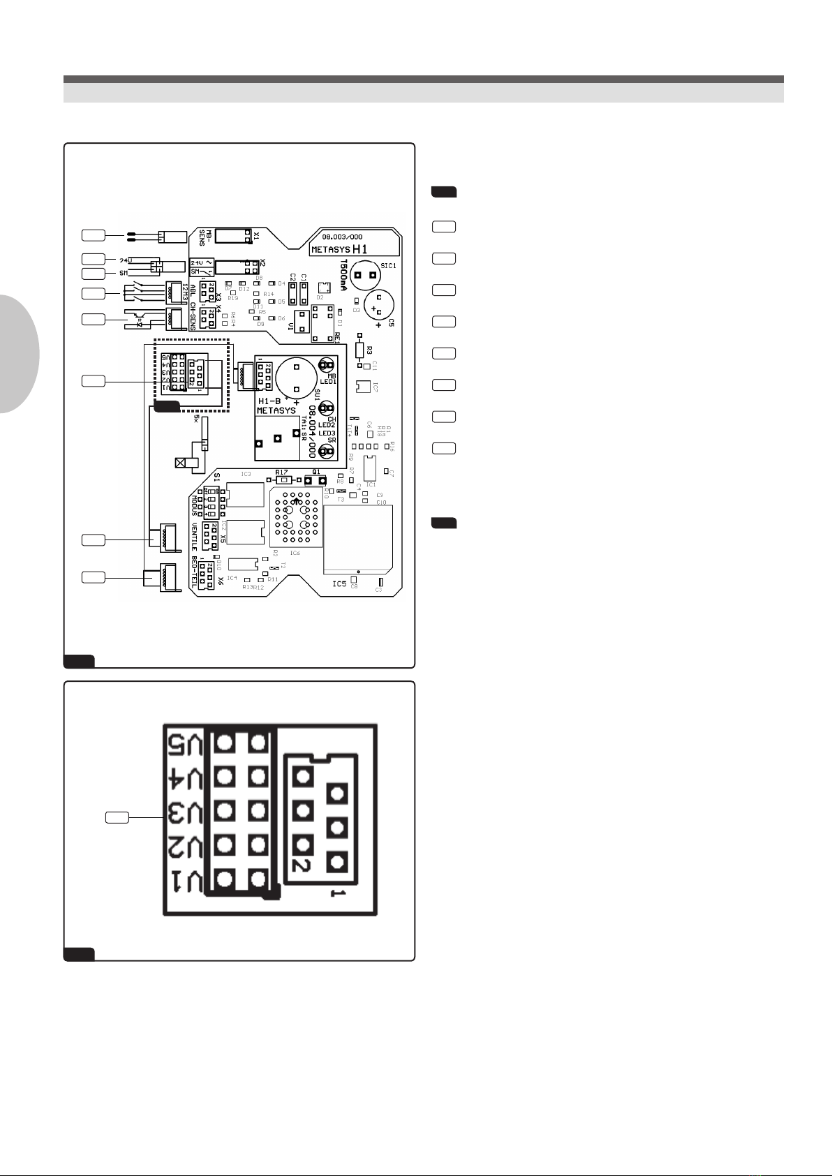
13. Electronic circuit board
29 Wiring diagram, see illustration
29.1 Membrane rupture sensor (X1 - MB- SENS)
29.2 Voltage supply 24 V ~(X2 - 24V ~)
29.3 Start of suction motor (X2 - SM)
29.4 Suction tube holder 1, 2 and 3 (X3 - ABL)
29.5 Sensor chemical tank (X4 - CH- SENS)
29.6 Valves V1 - V5 (X5 - VENTILE), 6-pole
29.7 Control panel (X6 - BED- TEIL)
29.8 Vacuum switch
30 Transition board, see illustration
V1 H2O
V2 GREEN&CLEAN H1
V3 Knee valve, right
V4 Knee valve, left
V5 Additional valve for third suction hose
Electronic circuit board
Technicians
31
32
ON
OFF
ON
OFF
31.2
31.1
32.1 32.2
13
EN
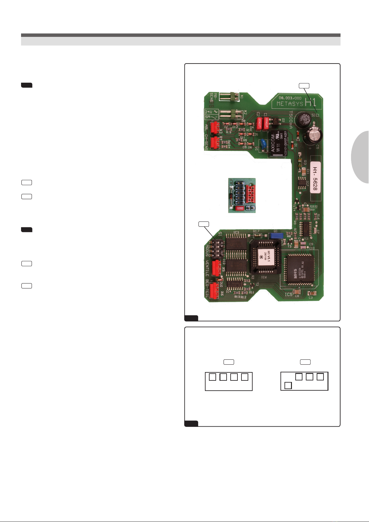
13. Electronic circuit board
31 See illustration
The voltage supply must be provided by a safety transformer that complies
with IEC 601-1 / VDE 0750 part 1 or DIN VDE 0551.
If the output contact X2 should switch electrical connections which are
not of type BF, a cut-off relay that complies with IEC 601-1, section 20.2,
insulation B-a must be used.
This cut-off relay is switched through the output contact X2, whereupon
the operating voltage used must be the same as of the H1 system.
31.1 H1 mode setting
31.2 SIC1. fuse (750m A/T; wired in)
32 H1 mode setting, see illustration
Switch 1:
32.1 Standard
1 - two suction hoses
32.2 3 suction hoses
0 - three suction hoses
Electronic circuit board
Technicians
33
34
35
36
1
4
2
3
Vaseline
PUSH
3
33.2
33.3
33.1
34.1
34.2
EN
14
14. Inspections
We recommend an annual service check of the Hygiene System H1 by an
authorised technician.
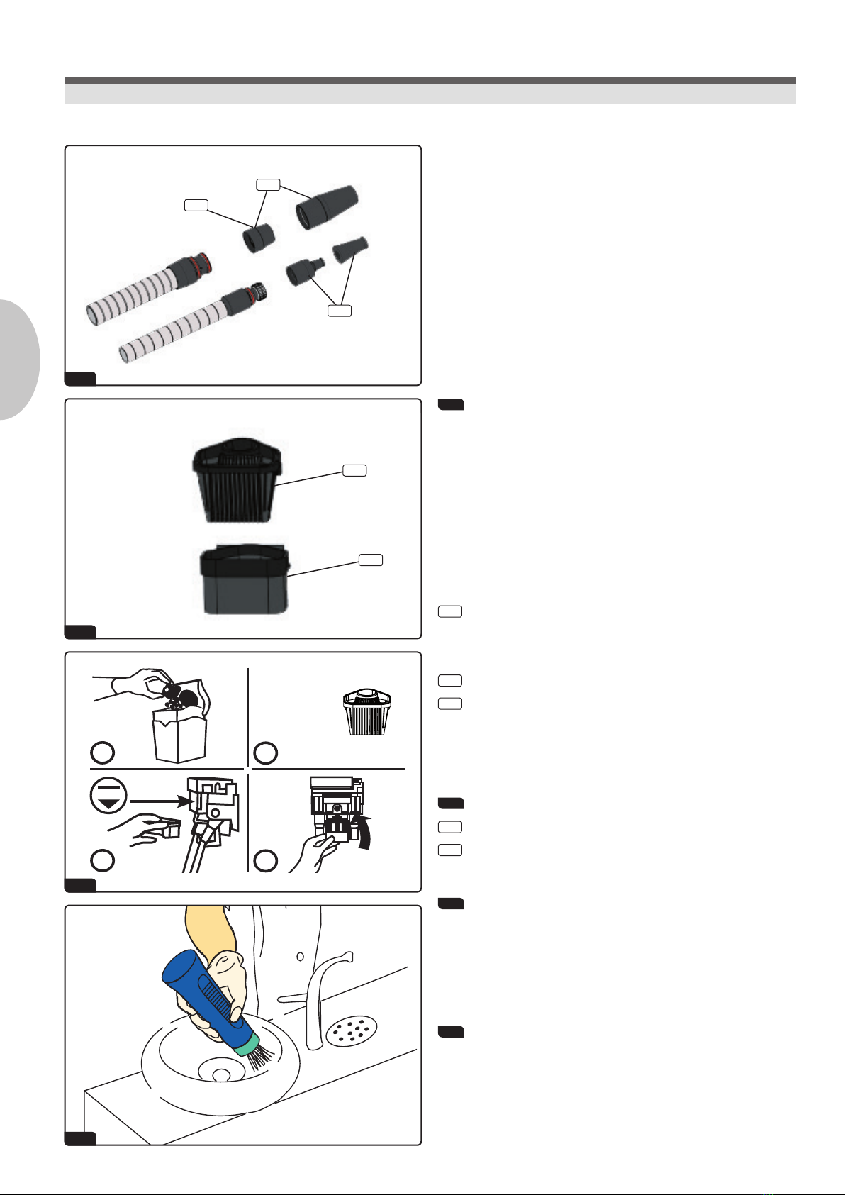
15. Cleaning and disinfection
The below mentioned parts can be cleaned and disinfected as follows:
33 Handpieces, see illustration
(This applies to METASYS handpieces only!)
The handpieces may be disassembled as follows: Switch off the unit and
pull the handpieces from the connecting piece of the tube with a gentle
twist.
Upon reassembly make sure that the O-rings are lubricated and in place,
and slide back the handpieces with a twist.
Small suction tube:
33.1 Handpiece, small - order no: 50010047
Large suction tube:
33.2 Handpiece, large - order no: 50010048
33.3 Distributor, large - Order no: 50010001
Grease the o-rings with vaseline after cleaning!
34 Prelter, see illustration
34.1 Filter rake - order no: 55010001
34.2 Filter cup - order no: 50010008
35 Lubricate the sealing lip with vaseline and place back properly!
The entire suction tubes can be disinfected with alcohol-free surface
disinfectants, such as GREEN&CLEAN MK or GREEN&CLEAN SK (wipe
disinfection). It is also possible to clean the suction tubes under running
water.
36 Cleaning the cuspidor, see illustration
We recommend GREEN&CLEAN MB to clean the cuspidor.
Do not use household cleaners because these can lead to malfunctions of
the suction system!
Inspections Cleaning and disinfection
Practice personnel, technicians

37 38
39
40
META SYS
METASYS
15
EN
16. Relling the H1 cartridge
A rell set is included in the scope of delivery!
37 Open the closure of cartridge
Attach key onto bayonet socket of cartridge.
Turn the key counter-clockwise.
38 Remove cover lid of the cartridge
Remove the cap.
Pull out plunger with cartridge seal.
39 Attach the lling adapter
Open the screw cap of the rell pouch.
Attach the short end of the adapter to the rell pouch.
Attach the long end of the adapter to the cartridge.
40 Rell the cartridge
Fill up the cartridge with GREEN&CLEAN H1 until the maximum level
is reached.
Remove adapter after use and rinse with water.
Close the rell pouch.
Insert plunger with cartridge seal in lling opening.
Attach the bayonet socket and turn the key clockwise.
17. Disposal
When the complete device is de-installed at the end of its service life
it must be returned to the manufacturer or disposed of appropriately in
accordance with the national regulations.
Refilling the H1 cartridge Disposal
Practice personnel, technicians

METASYS Medizintechnik GmbH
Florianistraße 3, 6063 Rum bei Innsbruck, Austria
1+43 512 205420 | 5+43 512 205420 7
METASYS ... makes the difference!
Visit us at:
GERMANY
+49 8823 938 44 33
FRANCE
+33 4 37 90 22 15
ITALY
+39 045 981 4477
2019-05 H1-55.005/01 Druck- und Satzfehler vorbehalten! / Subject to printing and setting errors!
Table of contents
Popular Dental Equipment manuals by other brands


Deldent
Deldent JETPOLISHER 2000 instructions

DentalEZ
DentalEZ StarDental Star Simplicity FX instruction manual

Instrumentarium
Instrumentarium Orthopantomograph OP200 D user manual

Ivoclar Vivadent
Ivoclar Vivadent Programat EP 5010 operating instructions

DENTAURUM
DENTAURUM Herbst IV Instructions for use

Gendex
Gendex Expert DC installation manual

HAGER WERKEN
HAGER WERKEN PRAXIPOL PS II Instructions for use

Renfert
Renfert Waxlectric light I instruction manual

Renfert
Renfert POWER quick start guide

Dentsply Sirona
Dentsply Sirona CEREC Primescan AC Unpacking and installation instructions

Wassermann
Wassermann HSS-99 Replacement manual

Jorvet
Jorvet J0453 user manual