Page 4
CLEANING AND LUBRICATION:
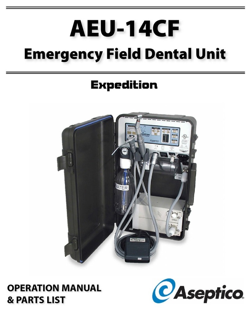
When servicing the AEU-14CF Emergency Field Dental
Unit, the parts of any component disassembled should be
thoroughly cleaned and inspected before reassembly. A hot
detergent solution is an effective cleaner on all non-
electrical parts. Flush all non-electrical parts with clear, hot
water. Abrasive cleaners have the potential to damage
surface finishes and should be avoided. Any wiping should
be done with a soft lint-free cloth.
Electrical parts should be cleaned with an appropriate
electrical parts cleaner or air.
Use a silicone base lubricating grease, such as Dow
Corning No. 103 to lubricate O-rings and seals in the
system. Before performing any reassembly of parts that
contain O-rings or seals, apply a light coat of silicone
grease. This will make installation easier and prevent the
O-rings or seals from being damaged.
ROUTINE MAINTENANCE:
WATER LINES - Disinfect the water lines weekly. Prepare
a 1:10 bleach solution (1 part household bleach to 10 parts
water). Remove water reservoir and discard residual water.
Replace empty water supply tank and air purge all
waterlines. Fill water supply tank with bleach solution. Run
bleach solution through all lines. Allow bleach solution to
stand in lines for 10 minutes. Remove water supply tank
and discard bleach. Flush water supply tank and all lines
thoroughly with clean water. Air purge and leave lines dry
until next clinical use.
ESD PRECAUTIONS:
The following electrostatic controls must be used when
working on this unit:
ESD Training and Standards:
Employees handling electronic sub-assemblies and ESD
sensitive components are expected to be trained.
Training should be based on IPC-A-610 or equivalent
ESD standard ANSI/ESD-S-20-20 – Protection of
Electrical and Electronic Parts, Assemblies and
Equipment.
ESD Static Controlled Area:
Areas that are designated for handling and working on
electronic sub-assemblies or their components should be
marked off with signs indicating the area where ESD
controls are to be enforced. These areas are to be kept
clear from persons that are not trained to prevent ESD
damage from occurring.
ESD Environment:
The work area is to be free of all static generating
materials, such as plastic containers, water bottles, plastic
bags, plastic objects, such as plastic pens, heat guns
(unless made for the ESD environment).
ESD Jackets:
Clothing should be non-static generating (cotton).
Static generating clothing (e.g. wool, acrylic, nylon) must
be covered with an ESD jacket that is buttoned closed.
Optional gloves:
Nitrile gloves may be used to cover the hands when
working, but are not required.
Seating:
ESD Chairs should be used in place of static generating
chairs (e.g. modern office seating use static generating
materials).
Storage and packaging:
All circuit boards and components are to be stored on or
in static dissipative or static shielding material, throughout
shipping and storage.
ESD Wrist Strap and Mat Routine Checks:
The wrist strap should be checked daily using an ESD
wrist strap testing station. See chart below.
ESD mats should be checked at least quarterly.
