Nittan EVA-PYH User manual

DW1500274
Rev.K3
Mar 6, 2017
Installation Instructions
Before Installation
Please read these instructions carefully and keep for future
reference.
The information in this document is subject to change without
notice. For updates please refer to our website.
CAUTION
!
・Do not use the products outside the rated power supply voltage
range specified in the Specifications. It may cause a fire or
damage to equipment.
・Do not disassemble, repair, or modify the products. It may cause
a fire or electric shock.
・Make sure to turn the power off before commencing any wiring
work. Otherwise it may cause electric shock or damage to
equipment.
・Do not use any tester other than the one specified for testing. It
may cause damage to equipment.
Note
・Follow the requirements for the installation of the products in
accordance with the Specifications. Otherwise it may cause
malfunction.
・The products should not be installed in the following places, as it
may cause damage to equipment:
- Place with plenty of air flow (close to a ventilation fan, air
conditioner, or place with drafts)
- Place close to heating appliance
- Place with a constantly high temperature or humidity
- Place with lots of dust or insects
- Place with exhaust gas such as garage
- Place where oil, dust, iron powder, chemicals, or hydrogen
sulphide may occur or affect the products
These instructions explain how to install and test UL Listed Nittan
detectors and bases.
For the details of each product, please refer to “Instruction Manual”
on the website: http://www.nittan.com
Table 1: UL Listed Product Instruction Manual
CAUTION
!
Install the detectors/bases in accordance with these instructions,
applicable NFPA standards, local codes, and the authorities
having jurisdiction. Failure to follow these instructions may result
in failure of detectors to initiate an alarm condition. Nittan is not
responsible for detectors and bases that have been improperly
installed, tested, or maintained.
Table 2: Electrical box for base
BASE Model
Applicable electrical box
3-1/2” Oct
4” Oct
4” Square
EVA-UB4
✓
-
-
EVA-UB4-6
✓
✓
✓
EVA-S6 Base
✓
✓
✓
EVA-STB-RL
✓
-
-
EVA-STB-RL
with
STBA-ADP
-
✓
✓
EVA-STB-SCI
✓
-
-
EVA-STB-SCI
with
STBA-ADP
-
✓
✓
Connect wiring to the detectors/bases as shown in the Section2.
Detectors and bases may be mixed on the same initiating loop as
long as the number of two-wire powered detectors does not
exceed the specifications of the control panel. For the
specifications of detectors/bases, see Table 3.
Product category
Model number
Manual part
number
Version
Control Panel
NFU-7000 series
LT-894NIT
Rev 2.1
Detector
EVA-PY
DW1401832
Rev.K1
EVA-PYH
DW1401831
Rev.K1
EVA-H2
DW1401833
Rev.K1
EVA-H2-H
EVA-DPH
DW1401834
Rev.K1
EVCA-P(-Z)
DW1500110
Rev.K2
Base
EVA-UB4
DW1401959
Rev.K1
EVA-UB4-6
EVA-STB-RL
DW1401853
Rev.K1
EVA-STB-SCI
DW1401852
Rev.K1
EVA-S6 Base
DW1401960
Rev.K1
Module
EVA-DIP-SCI
DW1401989
Rev.K1
EVA-DOP-SCI
DW1401991
Rev.K1
EVA-DOP
-AC240V-SCI
DW1401992
Rev.K1
EVA-SCI
DW1401994
Rev.K1
EVA-SCM-SCI
DW1401995
Rev.K1
EVA-MiniIP
DW1401993
Rev.K1
EVA-ZMU-SCI
DW1401990
Rev.K1
End of line
PCE
DW1401961
Rev.K1
Adapter Mounting
Plate
STBA-ADP
DW1402124
Rev.K1
NITTAN COMPANY, LIMITED
1-54-5 SASAZUKA, SHIBUYA-KU, TOKYO 151-8535, JAPAN
http://www.nittan.com

DW1500274
Rev.K3
Mar 6, 2017
1. Specifications
Detector
EVA-PYH
EVA-PY
EVA-DPH
Detector Element
Smoke : LED (Peak wavelength: 630 nm)
PD (High-output, high-speed silicon photodiode)
Heat: Thermistor (Negative temperature coefficient)
LED (Peak wavelength: 630 nm)
PD (High-output, high-speed silicon
photodiode)
Smoke : Blue LED (Peak wavelength: 465 nm)
Particle : IR LED (Peak wavelength: 940 nm)
PD (High sensitivity, Low dark current photodiode)
Heat: Thermistor (Negative temperature coefficient)
LED Visual Indicator
Stand-by - Flashing green LED
Alarm - Solid red LED with flashing green
Alarm - Solid red LED with flashing
green
Alarm - Solid red LED with flashing green
Operating Voltage Range
20 VDC to 38 VDC Peak
20VDC to 38VDC Peak
20 VDC to 38 VDC Peak
System Voltage
35VDC
35VDC
35VDC
Stand-by Current
200 µA
200 µA
200 µA
Alarm Current (with red LED)
5 mA
5 mA
5 mA
Sensitivity (Only for smoke Detector)
0.66 %/Ft. to 3.49 %/Ft.
0.69 %/Ft. to 2.86 %/Ft.
0.5 %/Ft. to 0.96 %/Ft.
Fixed Heat Alarm Temperature
57⁰C (135°F)
―
57⁰C (135°F)
Rate of Rise Detection
Responds to greater than 8.3°C (15°F)/min.
―
Responds to greater than 8.3°C (15°F)/min.
UL Ambient Installation Temperature
0⁰C to +38⁰C (32°F to 100°F)
Operating Temperature
-10⁰C to +55⁰C (14°F to 131°F)
-10⁰C to +55⁰C (14°F to 131°F )
-10⁰C to +55⁰C (14°F to 131°F)
Storage Temperature
-20⁰C to +60⁰C (-4°F to 140°F)
-20⁰C to +60⁰C (-4°F to 140°F )
-20⁰C to +60⁰C (-4°F to 140°F)
Relative Humidity
≦RH95% non-condensing
Address
1-254 (decimal)
1-254 (decimal)
1-254 (decimal)
Maximum quantity per loop
254 units *1
254 units *1
254 units *1
Standard
UL268 and UL521
UL268
UL268 and UL521
EVA-H2,H2-H
Sensing Element
Thermistor (Negative temperature coefficient)
LED Visual Indicator
Stand-by - Flashing green LED
Alarm - Solid red LED with flashing green
Operating Voltage Range
20 VDC to 38 VDC Peak
System Voltage
35 VDC
Stand-by Current
200 µA
Alarm Current (with red LED)
5 mA
Fixed Alarm Temperature (Model - EVA-H2)
57°C (135°F)
Rate of Rise Detection (Model –EVA-H2)
Responds to greater than 8.3°C (15°F)/min.
Fixed Alarm Temperature (Model - EVA-H2-H)
83°C (181.4°F)
UL Ambient Installation Temperature (Model-
EVA-H2)
0°C to 38°C (32°F to 100°F)
UL Ambient Installation Temperature (Model
-EVA-H2-H)
0°C to 65.6°C (32°F to 150°F)
Operating Temperature (Model- EVA-H2)
-10°C to +55°C (14°F to 131°F)
Operating Temperature (Model - EVA-H2-H)
-10°C to +65.6°C (14°F to 150°F)
Storage Temperature
-20°C to +60°C (-4°F to 140°F)
Charging Time
1 minute
Relative Humidity
≦RH95% non-condensing
Address
1-254 (decimal)
Maximum quantity per loop
254 units *1
Standard
UL521
EVCA-P(-Z)*2
Detector Type
Photoelectric Smoke Detector
LED Visual Indicator
Alarm - Solid red LED
Operating Voltage Range
12VDC to 32VD Peak
System Voltage
24VDC
stand-by Current
30μA ave. at 24VDC
Alarm Current
EVCA-P
68mA max.
47.5mA at 24VDC
EVCA-P-Z
68mA max.
When connected to EVA-ZMU-SCI:
20.5mA
Voltage Ripple
20% maximum
Sensitivity
1.78 %/Ft. to 3.60 %/Ft.
Alarm Characteristics
EVCA-P
6VDC in series with 375R between
+ (Terminal 3) and –(Terminal 1, 6) at 25°C
EVCA-P-Z
6VDC between
+ (Terminal 3) and –(Terminal 1, 6) at 25°C
UL Ambient Installation
Temperature
0⁰C to +49⁰C (32°F to 120°F)
Operating Temperature
-10⁰C to +55⁰C (14°F to 131°F)
Storage Temperature
-20⁰C to +60⁰C (-4°F to 140°F)
Relative Humidity
≦RH95% non-condensing
Maximum quantity per Module
20 units *1
Start-up Time
20 seconds
Standard
UL 268
*1 Refer to the Installation and Operation Manual of control panel
NFU-7000 series to determine correct loop load and maximum
loop resistance for devices connected to each loop.
*2 EVCA-P(-Z) can be connected with the analog addressable
module EVA-ZMU-SCI only.
EVA-STB-RL
SLC Applied Voltage
Rated Range 20 VDC to 38VDC
SLC Current Consumption
Standby 24μA Alarm/Activated 110μA
SLC Line impedance
Up to 50ohms, 2km (1.24mile)*1
RELAY
Switching capacity DC 30V/1A resistive
UL Ambient Installation Temperature
0oC(32oF) to 38oC(100oF)
Operating Temperature
-10oC(14oF) to 55oC(131oF)
Storage Temperature
-20oC(-4oF) to 60oC(140oF)
Max Relative Humidity
UP to 95% RH, non-condensing
Environment
Indoor dry use only
Terminal
Terminal for SLC: AWG 12 to 20
Terminal for Relay: AWG 14 to 22
Standard
UL268 and UL521
EVA-STB-SCI
SLC Applied Voltage
Rated Range 20 VDC to 38VDC
SLC Current Consumption
Standby 100μA Activated(SCI Isolation)
22mA
SLC Line impedance
Up to 50ohms, 2km (1.24mile)*1
SCI On Resistance
0.2ohms (max)
SCI Fault Detection Voltage
10V (min)
Visual Indicator (Status LED)
SCI LED (yellow)
UL Ambient Installation Temperature
0oC(32oF) to 38oC(100oF)
Operating Temperature
-10oC(14oF) to 55oC(131oF)
Storage Temperature
-20oC(-4oF) to 60oC(140oF)
Max Relative Humidity
UP to 95% RH, non-condensing
Environment
Indoor dry use only
Terminal
Terminal for SLC: AWG 12 to 20
Standard
UL268 and UL521
EVA-S6 Base
SLC Applied Voltage
Rated Range 20VDC to 38VDC
AUX. Supply Voltage
Rated Range 16VDC to 33VDC
SLC Current Consumption
Standby 0.5mA Alarm 1.4mA
AUX. Current Consumption
Standby 0.5mA Alarm 20mA
SLC Line impedance
UP to 50ohms, 2km (1.24mile) *1
AUX. Supply Line impedance
1.76 ohms@85 bases in alarm
UL Ambient Installation Temperature Range
0oC(32oF) to 38oC(100oF)
Operating Temperature
-10oC(14oF) to 55oC(131oF)
Storage Temperature
-20oC(-4oF) to 60oC(140oF)
Max Relative Humidity
UP to 95% RH, non-condensing
Environment
Indoor dry use only
Address
1-254(dec)
Maximum quantity per loop
127 units *1
Terminal
AWG 12 - 20
Conformity
UL268 and UL464
Detector
Base
EVA-UB4/EVA-UB4-6
UL Ambient Installation
0oC(32oF) to 38oC(100oF)
Temperature Range
Operating Temperature Range
-10oC(14oF) to 83C(181.4oF)
Storage Temperature
-20oC(-4oF) to 60oC(140oF)
Max Relative Humidity
UP to 95% RH, non-condensing
Environment
Indoor dry use only
Terminal
AWG 12-20
Conformity
UL268 and UL521
コメント:分かりやすくしてく
ださい。
(例えば、太字にするとか)
Table 3: Detector/base specifications

DW1500274
Rev.K3
Mar 6, 2017
2.Connections
UL Listed
Control
Panel
NFU-7000
Series
LOOP+
LOOP-
LOOP+
LOOP-
1
EVA-STB-RL
6
3N/O
COM
N/C
1
EVA-STB-RL
6
3N/O
COM
N/C
LOOP+
LOOP-
LOOP+
LOOP-
UL Listed
Control
Panel
NFU-7000
Series EVA-UB4/
EVA-UB4-6
3
561EVA-UB4/
EVA-UB4-6
3
561
EVA-S6 Base
EVA-STB-RL
EVA-UB4/EVA-UB4-6
Connect to UL Listed two wire
detector EVCA-P(-Z) for Class A
wiring.
To UL Listed control
panel NFU-7000 series
To UL Listed control
panel NFU-7000 series
Connect to UL Listed two wire
detector EVCA-P(-Z) for Class B
wiring.
Connect to UL Listed analog detector
EVA-PY, EVA-PYH, EVA-H2, EVA-DPH
or EVA-H2-H.
Optional wiring for Class A
Connect PCE for open
circuit monitoring.
Optional wiring for Class A
Connect to optional equipment
Output (Normal status)
・Close between N/C-COM
・Open between N/O-COM
3
65
1
3
65
1
UL Listed
Module
EVA-ZMU-SCI
A+
A-
B+
B-
L-
L+
EVA-UB4 EVA-UB4-6
3
65
EVA-UB4 EVA-UB4-6
1
3
65
1
UL Listed
Module
EVA-ZMU-SCI
A+
A-
EOL
+
-
10KΩ
L-
L+
UL Listed
Control
Panel
LOOP+
LOOP+
LOOP-
I+
1
6
I+
1
6
PCE
+24V
24VG
A+
L+
AUX. PWR+
LOOP-
AUX. PWR-
EVA-S6 Base EVA-S6 Base EVA-MinilP
L-
A-
A+ A-
I-
I-
NFU-7000
Series
UL Listed
Control
Panel
LOOP+
LOOP+
LOOP-
I+
1
6
I+
1
6
AUX. PWR+
LOOP-
AUX. PWR-
EVA-S6 Base EVA-S6 Base
I-
I-
NFU-7000
Series
EVA-S6 Base
UL Listed
Control
Panel
NFU-7000
Series 1
EVA-STB-SCI
65
1
EVA-STB-SCI
65
LOOP+
LOOP-
LOOP+
LOOP-
EVA-STB-SCI
Optional wiring for Class A
Connect to UL Listed analog detector
EVA-PY, EVA-PYH, EVA-H2 or
EVA-DPH.
Connect to UL Listed analog detector
EVA-PY, EVA-PYH, EVA-H2 or
EVA-DPH.
Connect to UL Listed analog detector
EVA-PY, EVA-PYH, EVA-H2 or
EVA-DPH.
Optional wiring for Class A
Connect to UL Listed analog detector
EVA-PY, EVA-PYH, EVA-H2 or
EVA-DPH.
Class A wiring is also applicable.

DW1500274
Rev.K3
Mar 6, 2017
3. Installation
SLC line impedance is 50Ω at maximum and the maximum length
is 2km.
Please refer to “Terminal”of the Specifications below for cables.
Refer to the control panel and/or module instruction manual to
determine correct maximum loop load and maximum loop
resistance for devices connected to each loop.
3.1 Wiring method
CAUTION
!
・For system monitoring –Do not use looped wire under terminals.
Break wire run to provide monitoring of connections.
・Do not connect different gauge cables at one terminal in order to
prevent loosening.
・Do not connect cables in reverse polarity. Failure to connect the
polarity correctly could result in damage to equipment.
3.2 Tamper Resistance Feature
The EVA-UB series, EVA-S6 Base, and EVA-STB series of
smoke/heat detector mounting bases have a tamper- resist
feature that works in conjunction with the detectors. When this
feature is enabled, the detectors cannot be removed from the
base without the use of a small hexagonal wrench. To avoid
unauthorized removal of the detector, turn the locking screw in
the mounting base counterclockwiseuntil the screw extends out
about 4 mm (3/16”) from the rim of the base, as shown in the FIG
2.
Note: If the detector is installed on a high celling where a tool
(such as a ladder) is needed, it is not recommended to
use the locking screw.
3.3 Use of dust cover
If the dust cover is not used during construction work, the
exposure to a slightly dusty environment can cause false alarms
after installing the detectors.
After the installation is completed, remove and discard the dust
cover.
3.4 Use of detector guard
Smoke detectors are not to be used with detector guards unless
the combination has been evaluated and found suitable for that
purpose.
Notes: • In the event of a false alarm, clean and re-install the
detector.
•If the detector still gives false alarms replace the
detector.
4. Testing
Notes: • Before testing, notify the proper authorities that the
system is undergoing maintenance, and will temporarily
be out of service.
•Disable the system to prevent unwanted alarms.
•All sensors must be tested after installation and
periodically thereafter.
•Testing methods must satisfy the Authority Having
Jurisdiction (AHJ).
•When carrying out site testing of the detector, the
control panel must be set to “One Man Walk Test” mode
prior to the test.
Sensors offer maximum performance when tested and maintained
in compliance with NFPA 72. The sensor may be tested in the
following ways:
Direct Heat Method (Hair dryer of 1000 –1500 watts)
1. From the side of the detector, direct the heat toward the
sensor. Hold the heat source about 15cm (6 inches)
away to prevent damage to the cover during testing.
2. The red LEDs on the detector should light when the
temperature at the heat detector reaches the alarm set
point. If the red LED indicator fails to light, check the
power to the detector and the wiring in the detector
base.
3. Reset the heat detector at the control panel. Detectors
that fail these tests should be cleaned in accordance
with MAINTENANCE Section in the instruction manual
of the detector and retested. If the detectors still fail
these tests they should be returned for repair.
Figure.1: Correct and incorrect wiring
method
Correct wiring
Incorrect wiring
Figure.2: Position of the locking screw
to lock the detector

DW1500274
Rev.K3
Mar 6, 2017
Direct Heat Method
(Heat Calibur HO-HC11 Heat Detector Tester)
1. Turn Master Power switch on and press the Power
button. LCD Display and LED’s should light.
2. Select Test Type by pressing the Test Type ↕ button,
the LED will light to display selected test type:
a. ROR - Rate of Rise Temperature Test
b. FIXED - Fixed Temperature Test
3. Select Test Mode by pressing the Test Mode ↕ button,
the LED will light to display selected test mode:
c. STD - Standard Test Mode
d. MULTI - Multiple Test Mode
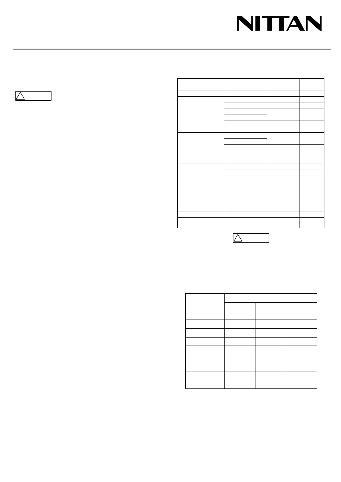
4. Select Temperature Range by pressing the Temp
Range ↕ button, the LED will light to display selected
Temperature Range:
a. HIGH - High Temperature Range
(190°F-210°F) - EVA-H2-H
b. LOW - Low Temperature Range
(100°F-135°F) - EVA-H2, EVA-PYH, EVA-DPH
5. Press and hold Start Test button for 2 seconds until
“Ready” is displayed on LCD.
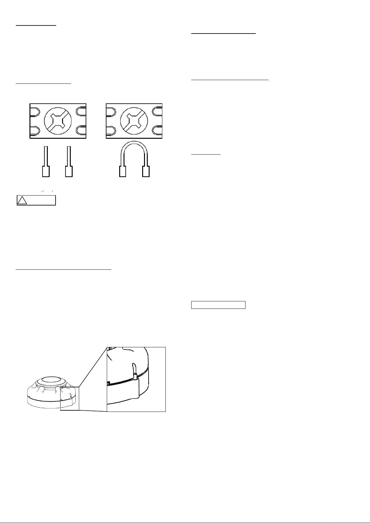
6. Place the Heat Detector Tester over the detector to be
tested to start the test, press the outer ring against the
ceiling to start test.
a. When the test has started a beep will sound, the
test will continue as long as the outer ring makes
contact with the ceiling.
b. Hold the Heat Detector Tester over detector until
the detector alarms.
7. Remove the Heat Detector Tester from the detector to
stop testing. The Heat Detector Tester will beep twice
when test is stopped, the fan will continue to run for 15
seconds to cool unit.
If the unit is not removed before set test length (60-90
seconds), the unit beeps twice and the display flashes
between “Error”, and “Timeout” to reflect that test
stopped before the detector alarmed.
8. If testing is complete, turn the Master Power switch off.
9. The red LEDs on the detector should light with the
green LED flashing when the temperature at the
detector reaches the alarm set point. If the red LED
indicator fails to light, check the power to the detector
and the wiring in the detector base.
10. Reset the heat detector at the control panel. Detectors
that fail these tests should be cleaned in accordance
with MAINTENANCE Section in the instruction manual
of the detector and retested. If the detectors still fail
these tests they should be returned for repair.
!CAUTION
Do not use heat guns used for paint stripping or soldering
pipes as these heat guns generate sufficient heat to
damage heatdetectors.
For the smoke detector testing (Go / No-Go)
1. For EVA-PY and EVA-PYH
To test the optical detector, introduce a certain amount
of aerosol into the detector’s head, using HSI FIRE &
SAFETY Aerosol canned smoke testers “25S” or “30S”.
Please follow the manufacturer’s recommendations on
their use.
For EVA-DPH
Use Smoke Detector Sensitivity Analyzer Model 501-B
(Gemini Scientific Corp.) to test the function of the
EVA-DPH.
Please follow the manufacturer’s recommendations on
their use except aerosol concentration setting.
Set the concentration of the analyzer to 1.0 %/ft. for this
testing.
For EVCA-P(-Z)
To test the optical detector, introduce a certain amount
of aerosol into the detector’s head, using Solo 330
Aerosol Dispenser with Solo A3 Smoke Detector Tester
(No Climb Products Ltd.). Please follow the
manufacturer’s recommendations on their use.
2. For EVA-PY and EVA-PYH
Check that the detector gives an alarm condition within
15 seconds. Check the red LED indicator is on and the
green LED is flashing on the detector. If the red LED
indicator fails to light, check the power to the detector
and the wiring in the detector base.
For EVA-DPH
Check that the detector gives an alarm condition within
40 seconds after the aerosol introduced into the
detector’s head. Check the red LED indicator is on and
the green LED is flashing on the EVA-DPH combination
detector. If the red LED indicator fails to light, check the
power to the detector and the wiring in the detector
base.

DW1500274
Rev.K3
Mar 6, 2017
For EVCA-P(-Z)
Check that the detector gives an alarm condition within
15 seconds. Check the red LED indicator lights on the
EVCA-P(-Z) smoke detector. If the red LED indicator
fails to light, check the power to the detector and the
wiring in the detector base.
3. After the detector has given the alarm condition, the
detector automatically is reset by the control panel. It
may be necessary to allow a short time to elapse
before resetting the detectors, to allow any residual
aerosol from the test to disperse.
4. Detectors that fail these tests should be cleaned in
accordance with MAINTENANCE Section in the
instruction manual of the detector and retested. If the
detectors still fail these tests they should be returned
for repair.
5. Before proceeding to the next detector, ensure that the
detector previously tested does not re-operate due to
the presence of residual aerosol.
For the smoke detector sensitivity
1. For EVA-PY, EVA-PYH and EVA-DPH
Detector sensitivity can be tested using Smoke
Detector Sensitivity Analyzer Model 501-B (Gemini
Scientific Corp.).
Please follow the manufacturer’s recommendations on
their use.
For EVA-PY and EVA-PYH:
Where the sensitivity limits for the Analyzer are 0.6 %/ft.
- 1.3 %/ft.
For EVA-DPH:
Where the sensitivity limits for the Analyzer are 0.3 %/ft.
- 0.5 %/ft.
For EVCA-P(-Z)
Detector sensitivity can be tested using Detector
Sensitivity Tester “Trutest”(No Climb Products Limited).
Please follow the manufacturer’s recommendations on
their use.
Where the sensitivity limits for the tester are 1.78 %/ft. -
3.60 %/ft.
2. For EVA-PY, EVA-PYH and EVA-DPH
Check that the detector gives an alarm condition within
40 seconds after the aerosol of which the concentration
controlled with the Analyzer was introduced into the
detector’s head. Check the red LED indicator is on and
the green LED is flashing on the detector. If the red
LED indicator fails to light, check the power to the
detector and the wiring in the detector base.
For EVCA-P(-Z)
Check the red LED indicator lights on the EVCA-P(-Z)
smoke detector within the sensitivity limits. If the red
LED indicator fails to light in the range, check the power
to the detector and the wiring in the detector base.
3. After the detector has given the alarm condition, the
detector automatically is reset by the control panel. It
may be necessary to allow a short time to elapse
before resetting the detectors, to allow any residual
aerosol from the test to disperse.
4. If the detector has a history of nuisance alarm, check
that the detector doesn’t give an alarm condition within
50 seconds when the aerosol less than low sensitivity
limit was introduced into the detector’s head.
5. Detectors that fail these tests should be cleaned in
accordance with MAINTENANCE Section in the
instruction manual of the detector and retested. If the
detectors still fail these tests they should be returned
for repair.
CAUTION
!
Do not disassemble, repair, or modify the products. It
may cause a fire or electric shock.
6. Before proceeding to the next detector, ensure that the
detector previously tested does not re-operate due to
the presence of residual aerosol.
7. FOR WARRANTY SERVICE, RETURN TO:
OVERSEAS BUSINESS DIVISION
NITTAN COMPANY, LIMITED
1-54-5 SASAZUKA, SHIBUYA-KU, TOKYO
151-8535, JAPAN
http://www.nittan.com
Other manuals for EVA-PYH
1
This manual suits for next models
11
Table of contents
Other Nittan Smoke Alarm manuals

Nittan
Nittan evolution EVC-P User manual

Nittan
Nittan EVA-PYH User manual

Nittan
Nittan Evolution EVC-DP User manual

Nittan
Nittan EVC-P User manual

Nittan
Nittan ST-P-OM User manual

Nittan
Nittan EVC-PY-IS User manual

Nittan
Nittan CKLD-KPT2 User manual

Nittan
Nittan EVCA-P User manual

Nittan
Nittan ST-P-AS User manual

Nittan
Nittan Evolution-Advanced EV-DP User manual