Metasys DH400 User manual

Fire Initiating Devices and Notification Appliances Technical Manual 408
Conventional Products Section
Technical Bulletin
Issue Date 1095
© 1995 Johnson Controls, Inc. 1
Code No. LIT-408160
Introduction Page 3
●
General Description 4
Installation Procedures 9
●
General Information 9
●
Installation 9
●
Mounting 10
●
Wiring Installation Guidelines 15
●
Perform Detector Check 18
Testing and Maintenance Procedures 19
●
Testing Duct Detectors 19
●
Testing Smoke Entry 19
●
Testing Standby, Alarm, and Sensitivity 21
●
Testing Alarms 21
●
Testing Sensitivity 23
●
Maintenance 24
●
Reinstallation 26
●
Detector Test Log 27
●
Sample of Test Log 27
●
Limitations 28
DH400 Conventional Air Duct Smoke Detector

2 Conventional Products—DH400 Conventional Air Duct Smoke Detector

Conventional Products—DH400 Conventional Air Duct Smoke Detector 3
Introduction
This document contains important information about installing,
maintaining, testing, and operating DH400 conventional air duct 2-wire
system powered smoke detectors. These conventional detectors are
manufactured by System Sensor for use with Johnson Controls systems.
If you install this detector for someone else to use, leave a copy of this
document with the user.
Before you install any DH400 air duct smoke detectors, read and be
familiar with:
●the control panel system installation manual
●the requirements of the authority having jurisdiction
●National Fire Protection Association (NFPA) Standards 72-National
Fire Alarm Code and 90A-Installation of Air Conditioning and
Ventilation Systems
●System Sensor Guide for Proper Use of System Smoke Detectors
Technical Bulletin in the Fire Initiating Devices and Notification
Appliances Devices Technical Manual (FAN 408), which provides
detailed information on detector spacing, placement, zoning, wiring,
and special applications
●or, for non-United States installations, applicable codes and standards
specific to country and locality of installation
Failure to follow these directions may result in failure of this device to
report an alarm or trouble condition or respond properly to an alarm
condition. Johnson Controls is not responsible for devices that have been
improperly installed, tested, or maintained by others.
As is the case with all installations under NFPA, Underwriters
Laboratories (UL), Underwriters Laboratories of Canada (ULC), National
Electric Code (NEC), Canadian Electrical Code classification, or any of
the building codes, final written approval of permissible operation and
configuration rests with the authority having jurisdiction.

4 Conventional Products—DH400 Conventional Air Duct Smoke Detector
A Heating, Ventilating, and Air Conditioning (HVAC) system supplies
conditioned air to virtually every area of a building. Smoke introduced
into this air duct system will be distributed to the entire building. Smoke
detectors designed for use in air duct systems are used to sense the
presence of smoke in the duct.
Table 1: Models
Air Duct Smoke Detector Housing Detector Model
DH400 1451DH Ionization Detector Head
2451 Photoelectronic Detector Head
For sampling tubes, see Table 4.
The 1451DH ionization or 2451 photoelectronic conventional smoke
detector head is combined with an efficient DH400 housing design that
samples air passing through a duct by using a single sampling tube
traversing the duct and allows detection of a developing hazardous
condition. When sufficient smoke is sensed, an alarm signal is initiated at
the fire control panel monitoring the detector, and appropriate action can
be taken to shut off fans, blowers, and change over air handling systems.
These actions can facilitate the management of toxic smoke and fire gases
throughout the areas served by the duct system.
DH400 detectors are designed to operate with 12 or 24 Volts Direct
Current (VDC) UL Listed compatible 2-wire control panels. The alarm
current must be limited to 100 mA or less by the control panel. Auxiliary
relay contacts for control purposes are not available for use with the
DH400. Control must initiate from the control panel.
For testing, the alarm can be initiated by a magnet activated test switch,
by insertion of a calibrated test card into the sensing chamber
(photoelectronic version only), or by the optional remote test station
(RTS451). The duct smoke detectors latch into an alarm state when the
alarm occurs. Light Emitting Diodes (LEDs) on each detector illuminate
to provide local alarm indication, and the optional RA400Z accessory
offers remote LED alarm annunciation capability.
The MOD400R is used with your Digital Multimeter (DMM) or voltmeter
to check the detector sensitivity as described in the MOD400R’s manual.
If the detector’s sensitivity limits or the MOD400R limits do not appear on
the back of the detector, the MOD400R is not suitable for field sensitivity
testing of that unit.
The DH400 duct detector must be reset by the control panel.
General
Description

Conventional Products—DH400 Conventional Air Duct Smoke Detector 5
Figure 1: Exploded View of Duct Detector Components
Table 2: Contents of the Duct Detector Kit
Item Quantity
Complete Housing Base and Cover Assembly 1
No. 10 Sheet Metal Mounting Screws 2
Sampling Tube Filters 2
Test Magnet 1
Drilling Template 1
5/16 in. (7.94 mm) O-rings 2
Rubber Tube Bushing Seals 2
No. 6 Self-tapping Mounting Screws for the
Sampling Tube 4
Exhaust Filter Adapter 1
Inlet Tube End Plug 1
No. 10 Speed Nuts 2
The inlet sampling tube must be ordered separately. It must be the correct
length for the width of the duct where it will be installed. To determine
the inlet tube required for different duct widths, read Table 4: Sampling
Inlet Tubes Required for Different Duct Widths in the Mounting, Install
the Sampling Inlet Tube section of this technical bulletin.
Foam
Gasket
Detector Base
Exhaust Filter
Adapter
Conduit Holes
Detector Head
(
Supplied Separatel
y
)
Samplin
g
Tube
Filters
Cover
Screws
Samplin
g
Tube
Mountin
g
Screws
DuctDetector
Cover
(
Clear Plastic
)
Tube End
Plu
g
Duct Detector
Housin
g
Terminal Strip
dh500
j
Test Ma
g
net
Inlet Samplin
g
Tube
(
Supplied Separtel
y
)
O-rin
g
s
Housin
g
Mountin
g
Screws

6 Conventional Products—DH400 Conventional Air Duct Smoke Detector
Table 3: Specifications Summary
Description HVAC air duct mounted ionization or photoelectronic
smoke detector for 2-wire alarm systems
Environmental Limits
Temperature 32 to 120°F (0 to 49°C)
Humidity 10 to 93% Relative Humidity, Non-condensing
Air Velocity 300 to 4000 ft/min.
1.5 to 20.3 m/sec.
Test Features Magnetic Test Switch
MOD400R Test Module
RTS451 Remote Test Station
R59-18-00 Calibrated Test Card
Mechanical
Length 14.5 in. (368.3 mm)
Width 5 in. (127 mm)
Depth (installed) 4 in. (101.6 mm)
Weight 3.5 lb (1600 g)
Terminals Captive universal terminal screws with sems plates accept
wire sizes of 14 gauge or smaller. The screws will
withstand 10 in·lb of tightening torque without damage.
Accessories
M02-04-00 Replacement Test Magnet
RA400Z Remote Annunciator Alarm LED
RTS451 Remote Test Station, Test Switch with Alarm, and
Power LEDs
CRT400 Detector Head Cover Removal Tool (Ion only)
F36-05-00 Replacement Air Filter (two per package)
MOD400R Sensitivity Test Module
P48-21-00 Replacement End Plug for Inlet Sampling Tube
R59-18-00 Replacement Calibrated Test Card (for Photo Units Only)
RS14 Replacement Screen, Ionization Detector Head (1451DH)
RS24 Replacement Screen, Photoelectronic Detector Head
(2451)
A2650-01 Replacement Installation Kit (Mounting Hardware)
Sampling (Inlet) Tubes
Tube Outside Duct Width
ST-1.5 1 to 2 ft (300 to 600 mm)
ST-3 2 to 4 ft (600 to 1200 mm)
ST-5 4 to 8 ft (1200 to 2400 mm)
ST-10 8 to 12 ft (2400 to 3700 mm)
Exhaust Tube Extension
A2440-00 5.75 in. (146 mm) additional
Continued on next page . . .

Conventional Products—DH400 Conventional Air Duct Smoke Detector 7
Table 3 (Cont.): SpecificationsSummary
Electrical Ratings - includes Base and Detector
System Voltage 12/24 VDC
Maximum Ripple Voltage 4 volts Peak-to-Peak
Startup Capacitance 0.02
µ
F Maximum
Standby Ratings 8.5 VDC Minimum
35 VDC Maximum
120
µ
A Maximum
Alarm Ratings 4.2 VDC Minimum at 10 mA
6.6 VDC Maximum at 100 mA
Alarm current must be limited to 100 mA or less by the
control panel. If used, the RA400Z remote lamp operates
within the specified alarm currents.
Reset Voltage 2.50 VDC Minimum
Reset Time 0.3 sec. Maximum
Startup Time 34.0 sec. Maximum

8 Conventional Products—DH400 Conventional Air Duct Smoke Detector

Conventional Products—DH400 Conventional Air Duct Smoke Detector 9
Installation Procedures
This section contains installation information for DH400 air duct smoke
detector. Instructions are given for mounting and wiring the detector, and
basic installation information is provided.
!
CAUTION: Personal injury hazard. This device will not
operate without electrical power. Frequently, fire
situations may cause an interruption of power. The
system safeguards should be discussed with your local
fire protection specialist.
This device will not sense smoke unless the ventilation system is
operating. This detector housing is not a weatherproof device; therefore, it
should not be installed above the building roof line and must be protected
from the elements.
1. Verify duct airflow direction and velocity.
2. Drill the mounting holes.
3. Secure the detector housing to the duct.
4. Install the sampling inlet tube.
5. Complete the field wiring.
6. Install the filters and check the pressure differential.
7. Perform the detector check.
8. Install the cover.
Model DH400 detectors are designed to be used in air handling systems
having air velocities of 300 to 4000 feet per minute. Be sure to check
engineering specifications to ensure that the air velocity in the duct falls
within these parameters. If necessary, an Alnor Model 6000-P velocity
meter or equivalent, may be used to check the air velocity in the duct.
General
Information
Installation
Installation
Sequence
Verify Duct
Airflow Direction
and Velocity
10 Conventional Products—DH400 Conventional Air Duct Smoke Detector
1. Remove the paper backing from the mounting template supplied.
2. Affix the template to the duct at the desired mounting location
oriented on the duct in compliance with the NFPA-72 standards
(Figure 5).
3. Make sure the template lies flat and smooth on the duct.
4. Center punch Holes A and B.
5. Drill the holes as indicated on the template.
6. Slide the two speed nuts over the two small holes (Hole A) next to the
sampling tube bushing holes (Hole B) previously drilled in the duct
(Figure 2).
dhfig2
Hole A
Hole B
Duct Wall
Speed Nut .....
Figure 2: Speed Nut Mounting Location
1. Remove the duct housing cover.
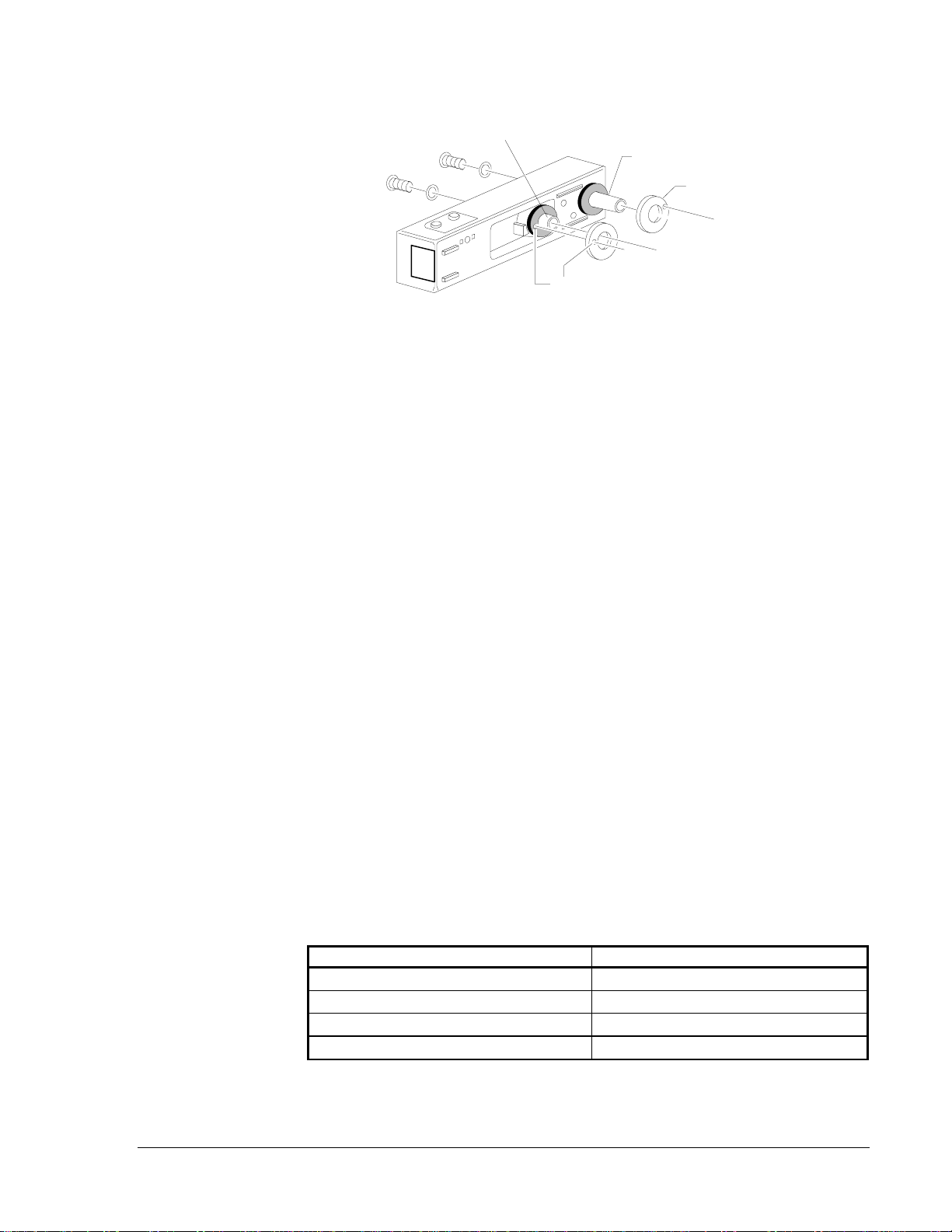
2. Slide the foam gaskets over the tube bushings (Figure 3).
3. Make sure the two small holes in the gaskets line up with the two base
mounting holes.
4. Put one 5/16 inch O-ring over each of the two No. 10 sheet metal
screws.
5. Use the two sheet metal screws to screw the detector housing to the
duct.
6. Do not overtighten the screws.
Mounting
Drill the Mounting
Holes
Secure the
Detector Housing
to the Duct
Conventional Products—DH400 Conventional Air Duct Smoke Detector 11
dhfi
g
2a
Duct Detector
Housin
g
Exhaust Tube
(
Extension Bushin
g
)
Foam Gaskets.....
O-rin
g
s
Mountin
g
Screws
Screw Holes for Attatchin
g
Detector Housin
g
to Duct
Inlet Samplin
g
Tube Bushin
g
Figure 3: Installation of Foam Gaskets over
Sampling Tube Bushings
The sampling inlet tube is identified by a series of air inlet holes on the
tube (Figure 4). This tube must be purchased separately. Order the
correct length for the width of the duct where it will be installed (Table 4).
The exhaust tube is molded onto the base of the duct housing, and the
A2440-00 exhaust tube extension is available as an accessory in those
cases where the molded exhaust port does not extend at least two inches
into the duct.
The inlet tube is always installed in the centermost housing bushing with
the air inlet holes facing into the airflow. The tube is inserted throught the
detector housing and into the duct, until the tube’s mounting flange makes
contact with the housing. See Figures 3 and 8 for two views of the
orientation of the sampling tube in the housing.
To assist proper installation:
●The tube’s mounting flange is marked with arrows.
●Make sure the inlet tube is mounted so that the arrows point into the
airflow.
●The various combinations of tube mounting configurations with
respect to airflow are described (Figure 5).
●Mounting the detector housing in a vertical orientation is acceptable,
provided that the air flows directly into the sampling tube (Figure 5).
Table 4: Sampling Inlet Tubes Required for Different Duct Widths
Outside Duct Width Inlet Tube Required
1 to 2 ft ST-1.5
2 to 4 ft ST-3
4 to 8 ft ST-5
8 to 12 ft ST-10
Install the
Sampling Inlet
Tube

12 Conventional Products—DH400 Conventional Air Duct Smoke Detector
dhfig3a
Airflow Direction
Sample Inlet Holes Inlet
Tube
End Plu
g
.....
Arrows should
face into airflow.
Flan
g
e
Figure 4: Air Duct Detector Inlet Sampling Tube
Airflow
Direction
Duct
Detector
Housin
g
Airflow
Direction
Airflow
Direction
Airflow
Direction
dhfig4
Dots Indicate Position of
Samplin
g
Tube Holes
Inlet
Tube
Exhaust
Tube
Duct
Detector
Housin
g
Duct
Detector
Housin
g
Duct
Detector
Housin
g
Inlet
Tube
Exhaust
Tube
Inlet
Tube
Exhaust
Tube
Figure 5: Tube Mounting Configurations with
Varying Airflow Direction
1. If the tube is longer than the width of the air duct:
Drill a 3/4 inch hole in the duct directly opposite the hole already cut
for the inlet tube.
2. If the tube is shorter than the width of the air duct:
Install the end plug into the inlet tube (Figure 5).
Sampling tubes over three feet long must be supported at the end
opposite the duct detector.
3. Slide the tube into the centermost housing bushing.
4. Position the tube so that the arrows point into the airflow.
Installation for
Ducts Less Than
Eight Feet Wide

Conventional Products—DH400 Conventional Air Duct Smoke Detector 13
5. Secure the tube flange to the housing bushing with two No. 6
self-tapping screws.
6. For tubes longer than the width of the air duct:
The tube should extend out of the opposite side of the duct.
7. If there are more than two holes in the section of the tube extending
out of the duct:
Select a different length (Table 4).
8. Otherwise, trim the end of the tube protruding through the duct so that
one to two inches of the tube extend outside the duct.
9. Plug this end with the end plug.
10. Tape close any holes in the protruding section of the tube.
11. Be sure to seal the duct when the tube protrudes.
Note: In no case should more than two air inlet holes be cut off the tube.
There must be a minimum of ten holes in the tube exposed to the
air stream.
To install inlet tubes in ducts more than eight feet wide, work must be
performed inside the air duct. Sampling of air in ducts wider than eight
feet is accomplished by using the ST-10 inlet sampling tube. If the tube is
shorter than the width of the air duct, install the end plug into the inlet
tube, and support the end opposite the duct detector (Figure 5).
To install the inlet tube:
1. Drill a 3/4 inch hole in the duct directly opposite the hole already
drilled for the inlet tube.
2. Slide the inlet tube with the flange into the centermost housing
bushing.
3. Position the tube so that the arrows point into the airflow.
4. Secure the tube flange to the housing bushing with two No. 6
self-tapping screws.
5. From inside the duct, couple the other section of the inlet tube to the
section already installed using the 1/2 inch conduit fitting supplied.
6. Make sure that the holes on both of the air inlet tubes are lined up and
face into the airflow.
7. Trim the end of the tube protruding through the duct so that
one to two inches of the tube extend outside the duct.
8. Plug this end with the end plug.
9. Tape close any holes in the protruding section of the tube.
10. Be sure to seal the duct when the tube protrudes.
Installation for
Ducts More Than
Eight Feet Wide

14 Conventional Products—DH400 Conventional Air Duct Smoke Detector
An alternate method to using the ST-10 is to use two ST-5 inlet tubes:
1. Remove the flange from one of the tubes, and install as described
above.
2. After the installation, use electrical tape to close off some of the
sampling holes so that there are a total of 10 to 12 holes spaced as
evenly as possible across the width of the duct.
Air currents inside the duct may cause excessive vibration, especially
when the longer sampling tubes are used.
In these cases:
1. Use a 3 inch floor flange (available at most plumbing supply stores) to
fasten the sampling tube to the other side of the duct.
2. When using the flange/connector mounting technique, drill a
1 to 1-1/4 inch hole where the flange will be used.
There may be applications where duct widths are not what is specified for
the installation. In such cases, it is permissible to modify an inlet
sampling tube that is longer than necessary to span the duct width.
1. Use a 0.193 inch diameter (No. 11) drill.
2. Add the appropriate number of holes so that the total number of holes
exposed to the airflow in the duct is 10 to 12.
3. Space the additional holes as evenly as possible over the length of
the tube.
This procedure should only be used in an emergency; it is not intended as
a permanent substitute for ordering the correct length tubes.
Interim
Modifications of
Inlet Sampling
Tubes

Conventional Products—DH400 Conventional Air Duct Smoke Detector 15
All wiring must be installed in compliance with the National Electrical
Code and the local codes having jurisdiction. Proper wire gauges should
be used. The conductors used to connect smoke detectors to control
panels and accessory devices should be color-coded to prevent wiring
mistakes. Improper connections can prevent a system from responding
properly in the event of a fire.
For Initiating Device Circuit (IDC) wiring, (the wiring between
interconnected detectors and the fire alarm control panel), it is usually
recommended that the single conductor wire be no smaller than
18 American Wire Gauge (AWG) (1.0 square mm). The duct detector
terminals accommodate wire sizes up to 14 AWG (2.1 square mm). Wire
sizes up to No. 14 AWG (2.1 square mm) for Terminals 8-14 and
No. 12 AWG (3.3 square mm) for Terminals 1-5 may be used with the
base. For best system performance, the IDC wires should be a twisted pair
and installed in a separate grounded conduit to protect the IDC from other
types of circuits in the system.
The last foot of conduit should be flexible steel conduit (available in
electrical supply houses), which facilitates easier installation and puts less
strain on the conduit holes in the housing. Solid conduit connections may
be used if desired.
Smoke detectors and alarm system control panels have specifications for
maximum allowable IDC resistance and supervision current. Consult the
control panel manufacturer’s specifications for the total IDC resistance
and supervisory current allowed.
Figure 6: System Wiring Diagram for 2-Wire Duct Detectors
(Detectors Powered from the Initiating Circuit)
Wiring
Installation
Guidelines
St
y
le D Optional Wirin
g
(
Class A
)
dhfi
g
15
5
3
4
12
UL Listed
Compatible
2-wire
Control Panel
Initiatin
g
Device
Circuit
In + Out
In Out
Supervisor
y
Switch
First Detector
on IDC DH400
RA400Z
(
Optional
)
Remote Alarm LED
5 mA Maximum
2.8 VDC
Nom in Alarm
5
4
3
12
In Out
In Out
Supervisor
y
Switch
Last Detector
on IDC DH400
RA400Z
(
Optional
)
Remote Alarm LED
5 mA Maximum
2.8 VDC
Nom in Alarm
EOLR
End-of Line
(
EOL
)
resistor
specified b
y
panel
manufacturer.
* Sprin
g
closes when detector head is removed from mountin
g
base. The installed head opens the sprin
g
, but internall
y
provides a short circuit between the two terminals.
Shortin
g
Jumper* Shortin
g
Jumper*

16 Conventional Products—DH400 Conventional Air Duct Smoke Detector
The DH400 detectors are designed for easy wiring. The housing provides
a terminal strip with clamping plates.
To make wiring connections:
1. Strip about 3/8 inch of insulation from the end of the wire. Use the
strip gauge molded into the base for ease of wiring to terminals.
2. Slide the bare end under the plate.
3. Break the wire at each terminal to ensure that the connections are
supervised (Figure 4).
Note: Do not loop the wire over the clamping plate.
4. Tighten the clamping plate screw.
DH400 detectors are designed to operate with 12 or 24 VDC UL Listed
2-wire compatible control panels. Alarm current must be limited by the
control panel to 100 mA or less.
The IDC zone wiring of the detector base should be checked before the
detector heads are installed in them. To make this possible, this base
contains a special spring-type shorting jumper. After a detector base is
properly wired and mounted on an electrical box, make sure that the
jumper is in contact with the base of Terminal 3. This temporary
connection shorts the negative-in and negative-out leads and permits the
wiring of the IDC to be checked for continuity.
Once all the detector bases have been wired and mounted and the IDC,
power, and optional releasing device control wiring has been checked, the
detector heads may be installed in the bases. The shorting jumper in the
base will disengage when the detector head is turned into place.
Note: Terminals 2, 3, and 5 do not use looped wire under terminals.
Break wire run to provide system supervision of connections.
This Not This
wirguide
Figure 7: Electrical Connections
Wiring the DH400
Conventional Products—DH400 Conventional Air Duct Smoke Detector 17
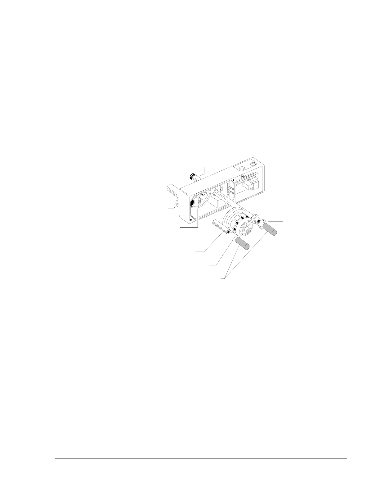
To install the sampling tube filters:
1. Push the filter adapter into the exhaust tube.
2. Push the filter onto the adapter tube on the left (Figure 8).
3. Install the other filter over the end of the inlet sampling tube.
Filters require periodic cleaning or replacement, depending on the amount
of dust and dirt accumulated. Visually inspect the filters at least quarterly.
Inspect them more often if the dust accumulation warrants it as described
in the Testing and Maintenance Procedure section of this technical
bulletin. The exhaust tube/intake tube filter P/N F36-05-00 is an example
of a replacement filter that can be ordered from System Sensor.
Foam
Gasket
Detector Base
Exhaust Filter
Adapter
Detector Head
Sampling Tube
Filters
Sampling Tube
Mounting Screws
dhfig13
Inlet Sampling Tube
Figure 8: Sampling Tube Filter Installation
Install the Filters

18 Conventional Products—DH400 Conventional Air Duct Smoke Detector
1. Perform the Standby and Trouble Tests as described in the Testing
Standby, Alarm, and Sensitivity section of this technical bulletin.
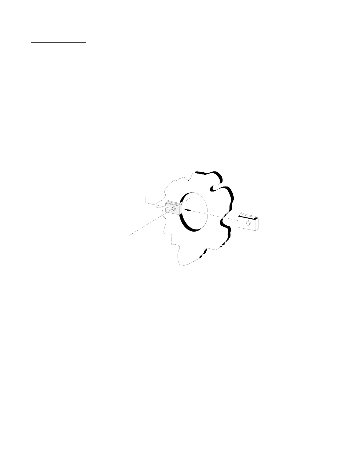
2. Perform the M02-04-00 Magnet Test as described in the Testing
Alarms section of this technical bulletin.
The RTS451 Remote Test Station Test as described in the Testing
Alarms section of this technical bulletin may substitute for this
requirement.
3. Perform the Airflow Test as described in the Testing Smoke Entry
section of this technical bulletin.
4. Perform the Smoke Response Test as described in the Testing Smoke
Entry section of this technical bulletin.
5. Perform the MOD400 or MOD400R Test and R59-18-00
Calibrated Test Card Tests as described in the Testing Sensitivity
section of this technical bulletin.
6. Record all test results in the Detector Test Log section of this
technical bulletin.
1. Install the cover using the four screws that are fixed in the
housing cover.
2. Be certain filters are installed as described in the Install the Filters
section of this technical bulletin.
3. Make sure the cover fits into the base groove and all gaskets are in
their proper positions.
4. Tighten the four cover screws to 10 in·lb.
Perform
Detector Check
Install the Cover

Conventional Products—DH400 Conventional Air Duct Smoke Detector 19
Testing and Maintenance
Procedures
Test and maintain duct detectors as recommended in NFPA 72-National
Fire Alarm Code. The tests contained in this manual were devised to
assist maintenance personnel in verification of proper detector operation.
Before conducting these tests, notify the proper authorities that the smoke
detection system will be temporarily out of service.
After a detector is set into alarm by one of the following test methods, and
the alarm activating device is removed from the detector, the system
should be reset at the control panel before testing any additional detectors.
After all testing is complete, notify the proper authorities that the system is
back in service.
All detectors must be tested after installation and periodically thereafter.
Testing methods must satisfy the authority having jurisdiction. Detectors
offer maximum performance when they are tested and maintained in
compliance with NFPA 72-National Fire Alarm Code.
After conducting these tests, record the appropriate information in the
Sample of Test Log section of this technical bulletin.
To verify sufficient sampling of ducted air, use a manometer to measure
the differential pressure created from airflow across the sampling tubes.
The pressure should measure no less than 0.01 inches of water and no
greater than 1.20 inches of water.
1. Visually identify any obstructions to determine if smoke is capable of
entering the sensing chamber.
2. Plug the exhaust and inlet tube holes to prevent ducted air from
carrying smoke away from the detector head.
3. Blow smoke such as cigarette, cotton wick, or punk directly at the
head to cause an alarm.
4. Remember to remove the plugs after this test, or the detector will not
function properly.
Testing Duct
Detectors
Testing Smoke
Entry
Airflow
Smoke Response
20 Conventional Products—DH400 Conventional Air Duct Smoke Detector
Duct
Housin
g
dhfig7a
Test Ma
g
net
Painted Side
Toward Housin
g
Detector
Head
Test Locator.....
Figure 9: Testing Detector Alarm
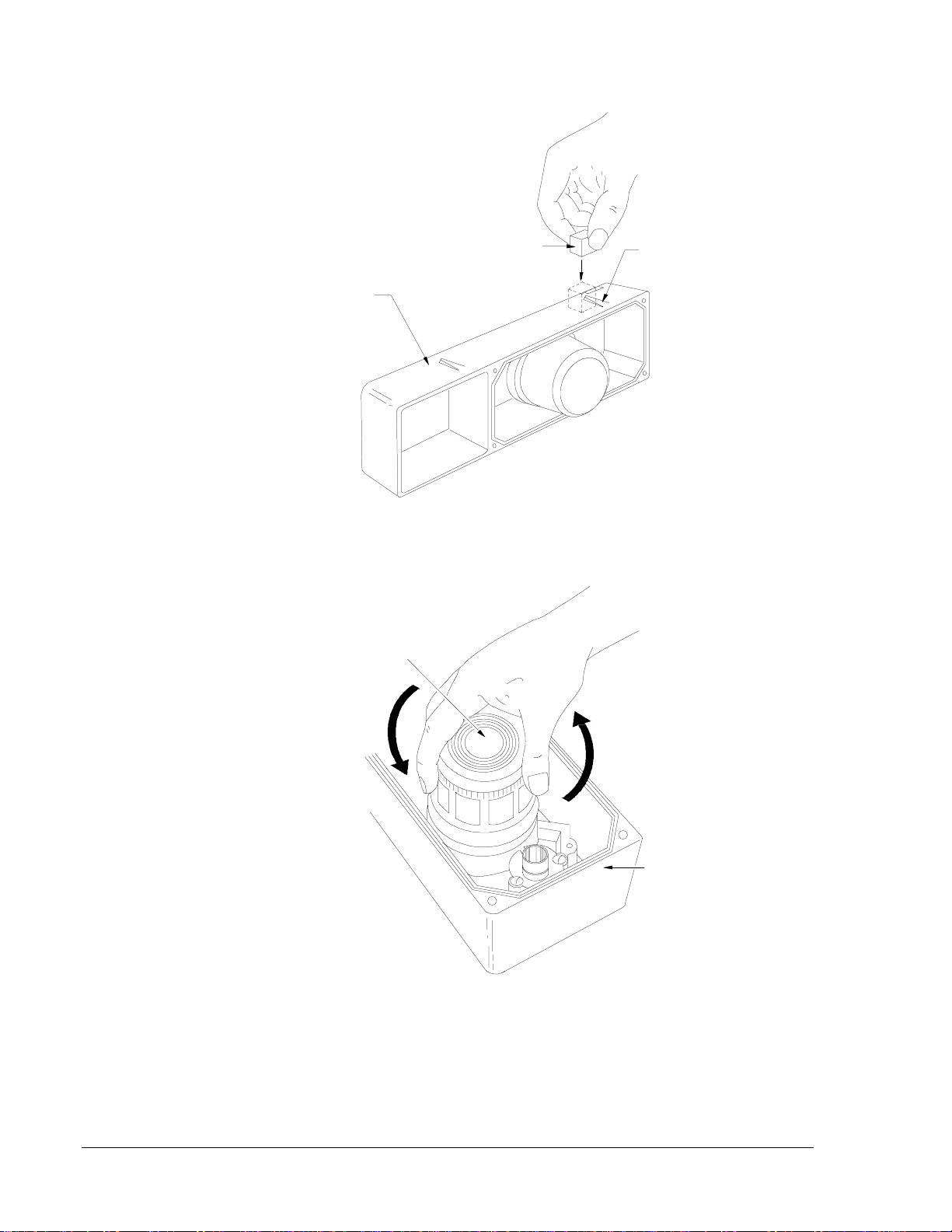
Twist
Counterclockwise
to Remove
Detector
Head
Twist
Clockwise
to Install
Duct
Housin
g
dhfig8a
Figure 10: Detector Head Removal
Table of contents
Other Metasys Smoke Alarm manuals

Metasys
Metasys 2251J User manual

Metasys
Metasys 2400AT Service manual

Metasys
Metasys 2551J User manual

Metasys
Metasys 2412 Series Service manual

Metasys
Metasys 7351J Service manual

Metasys
Metasys 2412AT User manual

Metasys
Metasys 6424 User manual

Metasys
Metasys 1400 User manual

Metasys
Metasys 1551J User manual


