turck TBIL-M1-16DIP User manual

Your Global Automation Partner
Instructions for Use
TBIL-M1-16DIP
I/O-Hub with IO-Link

2Hans Turck GmbH & Co. KG | T +49 208 4952-0 | F +49 208 4952-264 | [email protected] | www.turck.com

V01.00 | 2020/11 3
Table of Contents
1 About These Instructions.................................................................................................................. 5
1.1 Target groups................................................................................................................... 5
1.2 Explanation of symbols used ........................................................................................ 5
1.3 Additional documents.................................................................................................... 5
1.4 Feedback about these instructions.............................................................................. 5
2 Notes on the Product......................................................................................................................... 6
2.1 Product identification..................................................................................................... 6
2.2 Product identification..................................................................................................... 6
2.3 Scope of delivery ............................................................................................................. 6
2.4 Legal requirements.........................................................................................................6
2.5 Manufacturer and service.............................................................................................. 6
3 For Your Safety.................................................................................................................................... 7
3.1 Intended use..................................................................................................................... 7
3.2 General safety notes ....................................................................................................... 7
4 Product Description ........................................................................................................................... 8
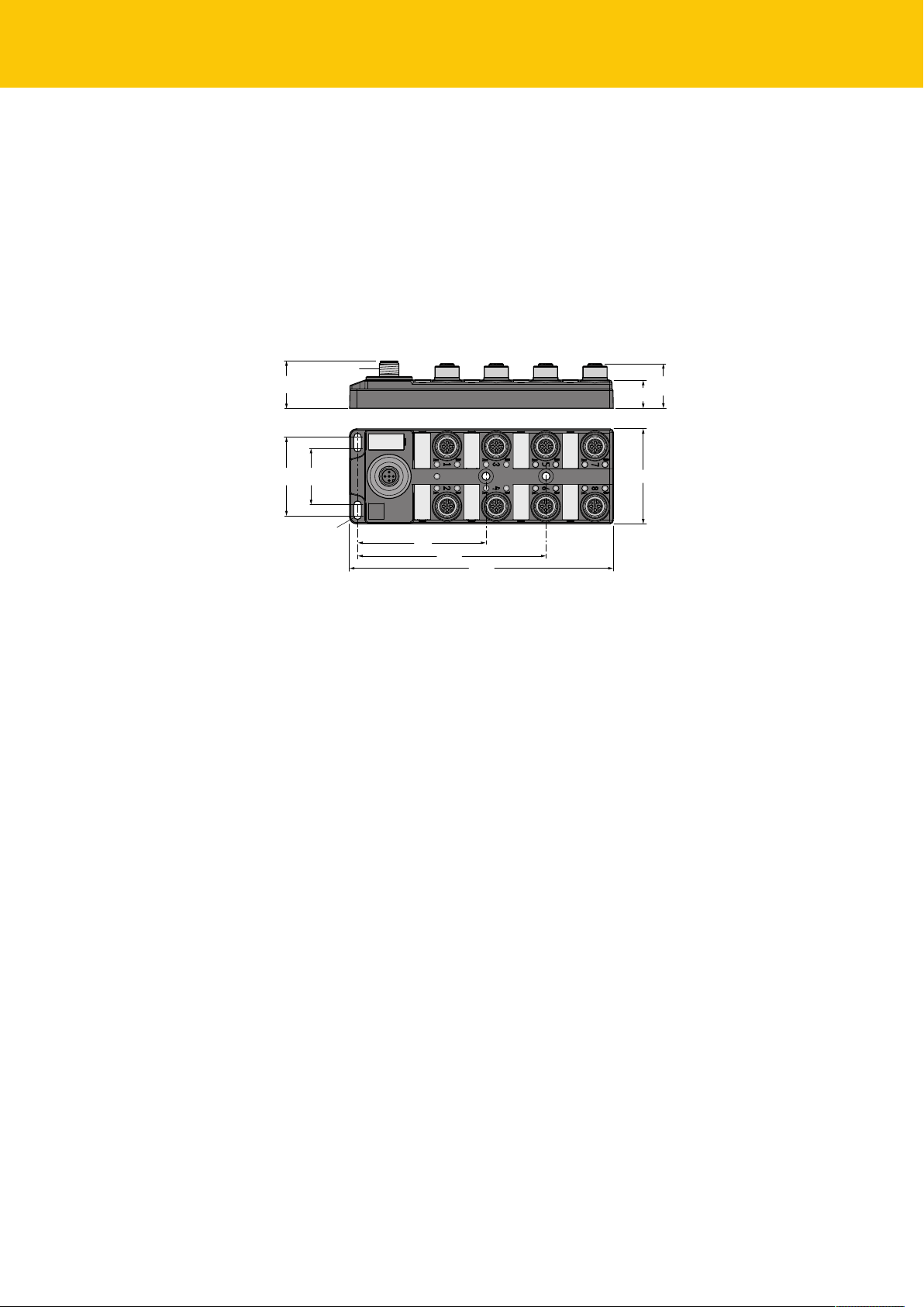
4.1 Device overview .............................................................................................................. 8
4.1.1 Display elements.............................................................................................................................. 8
4.2 Properties and features.................................................................................................. 8
4.3 Functions and operating modes ..................................................................................8
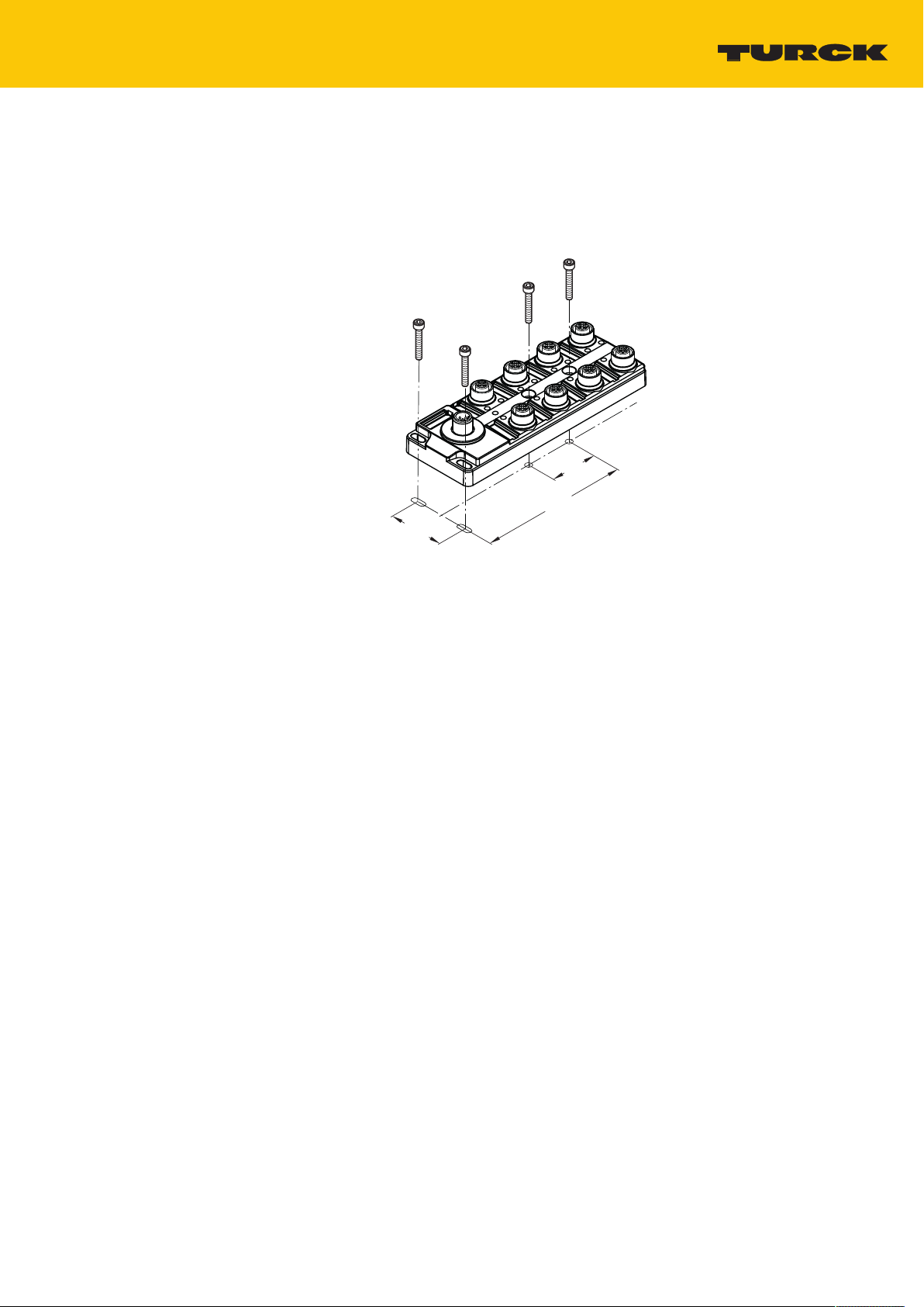
5 Installing............................................................................................................................................... 9
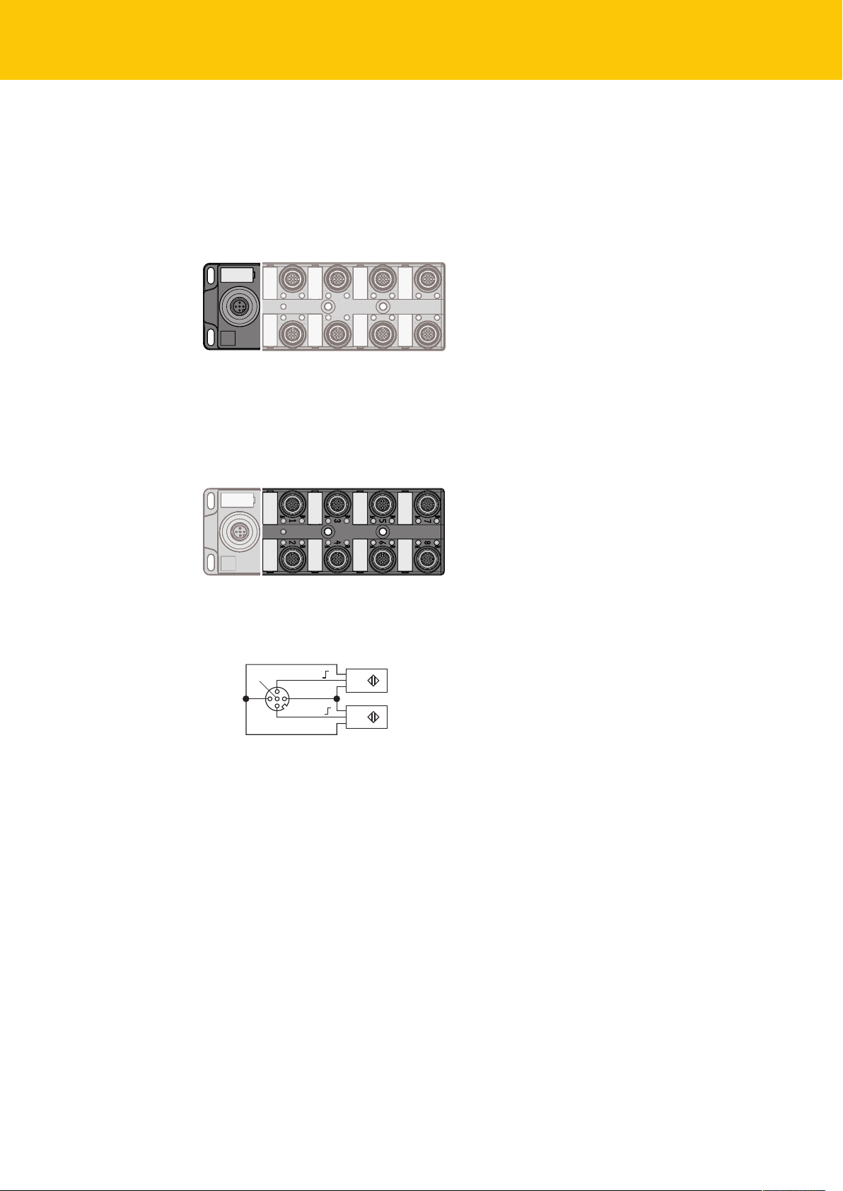
6 Connecting ........................................................................................................................................10
6.1 Connecting the supply voltage and IO-Link ............................................................10
6.2 Connecting digital sensors..........................................................................................10
7 Parameterizing and Configuring...................................................................................................11
7.1 Parameters......................................................................................................................11
7.2 System commands ........................................................................................................12
8 Operating ...........................................................................................................................................13
8.1 LED displays....................................................................................................................13
8.1.1 IO-Link................................................................................................................................................13
8.1.2 Channel-LEDs ..................................................................................................................................13
8.2 IO-Link events ................................................................................................................13
8.3 IO-Link error codes........................................................................................................14
9 Troubleshooting ...............................................................................................................................15
10 Maintenance......................................................................................................................................16
11 Repair..................................................................................................................................................16
11.1 Returning devices..........................................................................................................16
12 Disposal ..............................................................................................................................................16
13 Technical Data...................................................................................................................................17
14 Appendix: EU Declaration of Conformity ....................................................................................19

Table of Contents
4Hans Turck GmbH & Co. KG | T +49 208 4952-0 | F +49 208 4952-264 | [email protected] | www.turck.com

V01.00 | 2020/11 5
1 About These Instructions
These operating instructions describe the structure, functions and the use of the product and
will help you to operate the product as intended. Read these instructions carefully before using
the product. This is to avoid possible damage to persons, property or the device. Retain the in-
structions for future use during the service life of the product. If the product is passed on, pass
on these instructions as well.
1.1 Target groups
These instructions are aimed at qualified personal and must be carefully read by anyone
mounting, commissioning, operating, maintaining, dismantling or disposing of the device.
1.2 Explanation of symbols used
The following symbols are used in these instructions:
DANGER
DANGER indicates a dangerous situation with high risk of death or severe injury if
not avoided.
WARNING
WARNING indicates a dangerous situation with medium risk of death or severe in-
jury if not avoided.
CAUTION
CAUTION indicates a dangerous situation of medium risk which may result in minor
or moderate injury if not avoided.
NOTICE
NOTICE indicates a situation which may lead to property damage if not avoided.
NOTE
NOTE indicates tips, recommendations and useful information on specific actions
and facts. The notes simplify your work and help you to avoid additional work.
uCALL TO ACTION
This symbol denotes actions that the user must carry out.
aRESULTS OF ACTION
This symbol denotes relevant results of actions.
1.3 Additional documents
The following additional documents are available online at www.turck.com
nData sheet
nEU Declaration of Conformity
nCommissioning manual IO-Link devices
1.4 Feedback about these instructions
We make every effort to ensure that these instructions are as informative and as clear as pos-
sible. If you have any suggestions for improving the design or if some information is missing in
the document, please send your suggestions to [email protected].

Notes on the Product
Manufacturer and service
6Hans Turck GmbH & Co. KG | T +49 208 4952-0 | F +49 208 4952-264 | [email protected] | www.turck.com
2 Notes on the Product
2.1 Product identification
This instruction is valid for following devices:
nTBIL-M1-16DIP
2.2 Product identification
2.3 Scope of delivery
The scope of delivery includes:
nI/O hub
nDummy plugs for M12-connectors
nLabel clips
2.4 Legal requirements
The device falls under the following EU directives:
n2014/30/EU (electromagnetic compatibility)
n2011/65/EU (RoHS Directive)
2.5 Manufacturer and service
Hans Turck GmbH & Co. KG
Witzlebenstraße 7
45472 Mülheim an der Ruhr
Germany
Turck supports you with your projects, from initial analysis to the commissioning of your applic-
ation. The Turck product database contains software tools for programming, configuration or
commissioning, data sheets and CAD files in numerous export formats. You can access the
product database at the following address: www.turck.de/products
For further inquiries in Germany contact the Sales and Service Team on:
nSales: +49 208 4952-380
nTechnology: +49 208 4952-390
Outside Germany, please contact your local Turck representative.

V01.00 | 2020/11 7
3 For Your Safety
The product is designed according to state-of-the-art technology. However, residual risks still
exist. Observe the following warnings and safety notices to prevent damage to persons and
property. Turck accepts no liability for damage caused by failure to observe these warning and
safety notices.
3.1 Intended use
These devices are designed solely for use in industrial areas.
The block module TBIL-M1-16DIP is an O-Link device (Class A) and serves as I/O hub between
field devices (sensors) and the IO-Link master. The hub has 16 digital inputs. The device is de-
signed in IP65/IP67/IP69K and can be mounted directly in the field.
The devices may only be used as described in these instructions. Any other use is not in accord-
ance with the intended use. Turck accepts no liability for any resulting damage.
3.2 General safety notes
nThe device may only be assembled, installed, operated, parameterized and maintained by
professionally-trained personnel.
nThe device may only be used in accordance with applicable national and international regu-
lations, standards and laws.
nThe device only meets the EMC requirements for industrial areas and is not suitable for use
in residential areas.

Product Description
Functions and operating modes
8Hans Turck GmbH & Co. KG | T +49 208 4952-0 | F +49 208 4952-264 | [email protected] | www.turck.com
4 Product Description
The I/O hub TBIL-M1-16DIP connects up to 16 digital sensors with one IO-Link master port.
Eight M12 connectors are available for connecting the field devices. The I/O hub is connected
to the IO-Link master via an M12 socket. The devices are designed in a fully encapsulated hous-
ing with degree of protection IP65/IP67/IP69K.
4.1 Device overview
C1 C3
C2 C4
C5
C6
C7
C8
73
107
44,7 32,2
150
16 25,2
ø 4,3
54
M12 x 1
27,4
Fig.1: Dimensions
4.1.1 Display elements
The device has the following LED indicators:
nIO-Link communication
nI/O status
4.2 Properties and features
nFibre-glass reinforced housing
nShock and vibration tested
nFully potted module electronics
nProtection class IP65/IP67/IP69K
nIO-Link diagnostics for short-circuit and supply over- and undervoltage
n2 universal digital channels per connector
nMetal connectors
4.3 Functions and operating modes
The I/O hub TBIL-M1-16DIP connects up to 16 digital sensors with one IO-Link master port.
The device provides diagnostics for power supply and short circuit of the sensors and actuators
on the IO-Link master.

V01.00 | 2020/11 9
5 Installing
The device is mounted via four M4 screws on a flat and pre-drilled mounting surface.
Fasten the module to the mounting surface with 4 M4 screws. The maximum tightening
torque for the screws is 0.5 Nm
107
34
32.2 - 44.7
M4 (4 x)
max. 0.5 Nm
Fig.2: Mounting the device to a mounting plate

Connecting
Connecting digital sensors
10 Hans Turck GmbH & Co. KG | T +49 208 4952-0 | F +49 208 4952-264 | [email protected] | www.turck.com
6 Connecting
6.1 Connecting the supply voltage and IO-Link
The devices provide a 5-pin M12 connector for the connection to IO-Link.
Fig.3: M12 connector for the connection to IO-Link
Connect the device to power supply IO-Link according to the pin assignment below.
6.2 Connecting digital sensors
For connecting digital sensors, 5-pin M12 connectors are available.
Fig.4: M12 connector for connecting digital sensors (C1…C8)
Connect the sensors to the device according to the pin assignment.
5 FE 4 BK
1 BN +
3 BU –
3 BU –
2 WH
v
C1...C8
Fig.5: Pin assignment TBIL-M1-16DIP (C1…C8)
Supply sensors externally
sensors which are supplied externally can also be connected to the TBIL I/O hubs. When sensors
are supplied externally, the following safety regulations have to be observed:
Supply sensors from SELV or PELV power supplies.
Decouple external circuits that are not designed as SELV or PELV systems by opto-
couplers, relays or other measures.

V01.00 | 2020/11 11
7 Parameterizing and Configuring
7.1 Parameters
IO-Link object directory – ISDU device parameters: Direct Parameter Page
ISDU
Index
Hex.
(dec.)
Sub index Object name Access Length
in byte
Meaning/default value
0x00
(0)
Direct Parameter Page 1 Read
only
16
0x07 Vendor ID Read
only
2 ID for Turck:
0x013D
0x08
0x09 Device ID Read
only
3 TBIL-M1-16DIP:
0x1E3003
0x0A
0x0B
IO-Link object directory – ISDU device parameters: Identification
ISDU
Index
Hex.
(dec.)
Object name Access Length
in byte
Meaning/
default value
Comment
0x10
(16)
Vendor
name
Read
only
16 Turck
0x11
(17)
Vendor text Read
only
32 www.turck.com
0x12
(18)
Product
name
Read
only
32 TBIL-M1-16DIP
0x13
(19)
Product ID Read
only
16 Ident-No. of the device
6814100
0x14
(20)
Product text Read
only
32 I/O hub
0x15
(21)
Serial
number
Read
only
16 Sequential
serial number
0x16
(22)
Hardware ID Read/
write
8 Hardware version of
the device, e.g. V1.0
0x17
(23)
Firmware
revision
Read
only
16 Firmware version of
the device, e.g.
0x18
(24)
Application
Specific Tag
Read/
write
32 Default "***" Customer-specific or
application-specific
data can be stored in
this field.

Parameterizing and Configuring
System commands
12 Hans Turck GmbH & Co. KG | T +49 208 4952-0 | F +49 208 4952-264 | [email protected] | www.turck.com
IO-Link object directory – ISDU device parameters: Preferred Index (parameters and
diagnostics of the digital in- and outputs)
ISDU
Index
Hex.
(dec.)
Object name Access Length
in byte
Meaning
0x40
(64)
Parameter ID Read/
write
4 Customer-specific ID, for free use
0x41
(65)
Inverting
input
Read/
write
2 Invert digital input
Invert digital input – 0x41 (65), sub index 0
This parameter inverts the state of the digital input in the process image.
Format Length
Byte 2 byte 1 bit per channel
The default values are written in bold.
Value Meaning
0 No
1 Yes Input signal inverted
Byte 0 Byte 1
Bit offset Bit offset
7 6 5 4 3 2 1 0 15 14 13 12 11 10 9 8
Sub index Sub index
9 10 11 12 13 14 15 16 1 2 3 4 5 6 7 8
C8P2
(B)
C8P4
(A)
C7P2
(B)
C7P4
(A)
C6P2
(B)
C6P4
(A)
C5P2
(B)
C5P4
(A)
C4P2
(B)
C4P4
(A)
C3P2
(B)
C3P4
(A)
C2P2
(B)
C2P4
(A)
C1P2
(B)
C1P4
(A)
7.2 System commands
The device supports the following system commands (System Command).
General system commands (according to IO-Link specification)
Command
128 Device reset, the device is restarted.
130 Reset to factory settings

V01.00 | 2020/11 13
8 Operating
CAUTION
Operating the device outside the specification
Slight injuries and equipment damage possible.
Operate the unit only within the operating temperature specified in the tech-
nical data.
Use only thermally suitable connection cables.
8.1 LED displays
The device has the following LED indicators:
nIO-Link communication
nI/O status
8.1.1 IO-Link
IO-Link LED Meaning
Green flashing
(1 Hz)
IO-Link communication OK, valid process data are sent
Red IO-Link communication error or module error
Red flashing
(1 Hz)
IO-Link communication OK, invalid process data or diagnostic message
Off No voltage supply
8.1.2 Channel-LEDs
LED C1 A/B…C8 A/B Meaning
Green Input active
Off Input inactive
8.2 IO-Link events
Event
Code
Description Event Mode
0x5000 Hardware error 0xF4 (appears)
0xB4 (disappears)
0x5110 Overvoltage 0xF4 (appears) Overvoltage at supply
0xB4 (disappears)
0x5111 Undervoltage 0xF4 (appears) Undervoltage at supply
0xB4 (disappears)
0x7710 Overcurrent 0xF4 (appears) Group event:
Overcurrent of the sensor supply at one of
the connectors (C1…C8)
0xB4 (disappears)

Operating
IO-Link error codes
14 Hans Turck GmbH & Co. KG | T +49 208 4952-0 | F +49 208 4952-264 | [email protected] | www.turck.com
8.3 IO-Link error codes
Error code Description
0x8011 Index not available
0x8012 Sub index not available
0x8023 Accesss denied Index cannot be written
0x8030 Parameter value out of range
0x8033 Parameter length overrun Length of data to be written does not
match the length defined for this para-
meter.
0x8034 Parameter length overrun
0x8035 Function not available Function not available in the device
0x8041 Inconsistent parameter set

V01.00 | 2020/11 15
9 Troubleshooting
If the device does not function as expected, first check whether ambient interference is present.
If there is no ambient interference present, check the connections of the device for faults.
If there are no faults, there is a device malfunction. In this case, decommission the device and
replace it with a new device of the same type.

Maintenance
Returning devices
16 Hans Turck GmbH & Co. KG | T +49 208 4952-0 | F +49 208 4952-264 | [email protected] | www.turck.com
10 Maintenance
Ensure that the plug connections and cables are always in good condition.
The devices are maintenance-free, clean dry if required.
11 Repair
The device must not be repaired by the user. The device must be decommissioned if it is faulty.
Observe our return acceptance conditions when returning the device to Turck.
11.1 Returning devices
Returns to Turck can only be accepted if the device has been equipped with a Decontamination
declaration enclosed. The decontamination declaration can be downloaded from
https://www.turck.de/en/retoure-service-6079.php
and must be completely filled in, and affixed securely and weather-proof to the outside of the
packaging.
12 Disposal
The devices must be disposed of correctly and must not be included in general
household garbage.

V01.00 | 2020/11 17
13 Technical Data
Technical Data
Power supply
Operating/load voltage 24 VDC
Permisible range 20.4…30 VDC
Sensor/actuator supply VAUX Connector C1…C8 from power supply, short-circuit proof,
max. 120mA per connector
Power loss, typical ≤ 3,6 W
Inputs
Number of channels 16 digital pnp inputs (EN 61131-2)
Type of input diagnostics Group diagnostics
Signal voltage, low level -3…5 VDC (EN 61131- 2, type 1 and 3)
Signal voltage, high level 11…30 VDC (EN 61131- 2, type 1 and 3)
Input delay 0.010 ms
Max. input current 15 mA
Potential isolation Inputs to FE, 500 VDC
IO-Link
IO-Link specification Specified according to version 1.1
Parameterization FDT/DTM, IODD
Transmission rate COM 2: 38.4 kbit/s
Transmission physics 3-wire physics (PHY2)
Minimum cycle time 2.3 ms
Connectors
IO-Link M12 × 1, 5-pole
Input/output M12 × 1, 5-pole
Permissible torques
nIO-Link
nI/O channels
nMounting (M4 screws)
0.8 Nm
0.8 Nm
0.5 Nm
Standard/Directive conformity
Vibration test According to EN 60068-2-6
Shock test According to EN 60068-2-27
Drop and topple According to IEC 60068-2-31/IEC 60068-2-32
Electro-magnetic compatibility According to EN 61131-2/-6-4
Approvals CE, cULus
General Information
Dimensions (B × L × H) 54 × 150 × 27.4 mm
Operating temperature -40…+70 °C (for total current up to 4 A)
Storage temperature -40…+85 °C
Protection class IP65
IP67
IP69K
MTTF 139 years
Housing material PA6-GF30

Technical Data
18 Hans Turck GmbH & Co. KG | T +49 208 4952-0 | F +49 208 4952-264 | [email protected] | www.turck.com
Technical Data
Housing color Black
Halogen-free Yes
Mounting 4 mounting holes, Ø 4.3 mm
Approvals CE

V01.00 | 2020/11 19
14 Appendix: EU Declaration of Conformity
EU-Konformitätserklärung Nr.: 5035-4M
EU Declaration of Conformity No.:
Wir/ We:HANS TURCK GMBH & CO KG
WITZLEBENSTR. 7, 45472 MÜLHEIM A.D. RUHR
erklären in alleiniger Verantwortung, dass die Produkte
declare under our sole responsibility that the products
Kompakte I/O Module in IP20/IP67:
Compact I/O modules in
IP20/IP67:
FDN20-*, FNDL-*, FDNP-*,FDP20-*, FGDP,
FGEN-*, FLDP-*, FLIB-*, FXEN-*, TBDP-*,
TBEN-*, TBIL-*, TBEC-*, FEN20-*
auf die sich die Erklärung bezieht, den Anforderungen der folgenden EU-Richtlinien durch Einhaltung der
folgenden Normen genügen:
to which this declaration relates are in conformity with the requirements of the following EU-directives by compliance with the following
standards:
EMV - Richtlinie /EMC Directive 2014 / 30 / EU 26.02.2014
EN 61131-2:2007 (Abschnitte / section 8, 9, 10)
RoHS –Richtlinie /RoHS Directive 2011 / 65 / EU 08.06.2011
EN IEC 63000:2018
Weitere Normen, Bemerkungen:
additional standards, remarks:
Zusätzliche Informationen:
Supplementary infomation:
Mülheim a. d. Ruhr, den 29.09.2020
i.V. Dr. M. Linde, Leiter Zulassungen /Manager Approvals
Ort und Datum der Ausstellung / Name, Funktion und Unterschrift des Befugten /
Place and date of issue Name, function and signature of authorized person

Over 30 subsidiaries and over
60 representations worldwide!
www.turck.com
100024844 | 2020/11
100024844
Table of contents
Other turck Switch manuals

turck
turck IM1-451EX Series User manual

turck
turck TBIL-M1-16DXP User manual

turck
turck TBEN-L-SE-U1 Series User manual

turck
turck TBEN-L SE-M2 Series User manual

turck
turck TBIL-S Series User manual

turck
turck TBIP-L 16DXP-AUX Series User manual

turck
turck FMX-IM-3UP63X User manual

turck
turck TBIL-S Series User manual
Popular Switch manuals by other brands

Planex
Planex SW-2248F user manual

Accton Technology
Accton Technology CheetahSwitch Workgroup-3726M Quick installation guide

Analog way
Analog way Smart Edge FX (STE200) quick start guide

GarrettCom
GarrettCom Magnum ES42 Series Installation and user guide

Weidmuller
Weidmuller IE-SW-PL06M-2TX-4PoE Hardware installation guide

ZyXEL Communications
ZyXEL Communications GS2200 Series manual