METER ES-2 User manual

ES-2
Electrical Conductivity &
Temperature Sensor
Operator’s Manual
METER Group, Inc. USA
13890-01

ES-2
METER Group, Inc. USA
2365 NE Hopkins Court
Pullman WA 99163
Phone: 509-332-5600
Fax: 509-332-5158
Website: www.metergroup.com
sales.environmen[email protected]
Trademarks
c
2018 METER
All Rights Reserved
ii

ES-2 CONTENTS
Contents
1 Introduction 1
1.1 Customer Support . . . . . . . . . . . . . . . . . . . . 1
1.2 About This Manual . . . . . . . . . . . . . . . . . . . 1
1.3 Warranty ......................... 2
1.4 Seller’s Liability . . . . . . . . . . . . . . . . . . . . . . 2
2 About the ES-2 3
2.1 Specifications ....................... 3
3 Measurements 5
3.1 Temperature ....................... 5
3.2 Electrical Conductivity . . . . . . . . . . . . . . . . . . 5
4 Calibration 6
5 Connecting Sensors 7
5.1 Connecting to METER Logger . . . . . . . . . . . . . 7
5.2 Connecting to a Non-METER Logger . . . . . . . . . 8
5.3 Pigtail End Wiring . . . . . . . . . . . . . . . . . . . . 8
6 Installation 11
6.1 Pipe Water Monitoring . . . . . . . . . . . . . . . . . . 11
6.2 Tank Water Monitoring . . . . . . . . . . . . . . . . . 11
6.3 Cleaning Method . . . . . . . . . . . . . . . . . . . . . 12
7 Communication 13
7.1 SerialString........................ 13
7.2 SDI-12 Communication . . . . . . . . . . . . . . . . . 13
7.3 Common SDI-12 Commands . . . . . . . . . . . . . . . 14
7.4 SDI-12 Sensor Bus . . . . . . . . . . . . . . . . . . . . 14
7.5 SDI-12 Address . . . . . . . . . . . . . . . . . . . . . . 14
7.6 Power ........................... 15
7.7 Reading .......................... 15
8 Troubleshooting 16
9 Declaration of Conformity 17
iii

ES-2 1 INTRODUCTION
1 Introduction
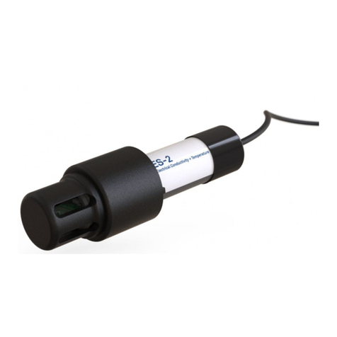
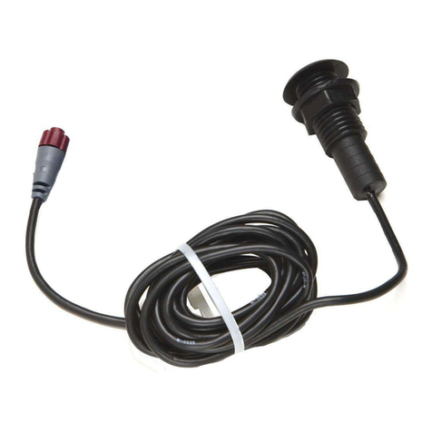
METER designed the ES-2 sensor to measure pipe water, tank water
(when used with protective cap).A thermistor in thermal contact
with the probe provides water temperature, while the screws on the
surface of the sensor form a four-electrode array to measure electrical
conductivity. This manual should help you understand the sensor
features and how to use it successfully.
1.1 Customer Support
There are several ways to contact METER if you ever need assis-
tance with your product, have any questions, or feedback. METER
has Customer Service Representatives available to speak with you
Monday through Friday, between 7am and 5pm Pacific time.
Note: If you purchased your sensor through a distributor, please con-
tact them for assistance.
Email:
sales.environmen[email protected]
Phone:
509-332-5600
Fax:
509-332-5158
If contacting us by email or fax, please include as part of your mes-
sage your instrument serial number, your name, address, phone, fax
number, and a description of your problem or question.
1.2 About This Manual
Please read these instructions before operating your sensor to ensure
that it performs to its full potential.
1

1 INTRODUCTION ES-2
1.3 Warranty
This sensor has a 30-day satisfaction guarantee and a one-year war-
ranty on parts and labor. Your warranty is automatically validated
upon receipt of the instrument.
Note: The one year service plan activates when METER ships the
instrument and not at the time of purchase.
1.4 Seller’s Liability
Seller warrants new equipment of its own manufacture against de-
fective workmanship and materials for a period of one year from the
date of receipt of equipment.
Note: We do not consider the results of ordinary wear and tear,
neglect, misuse, or accident as defects.
The Seller’s liability for defective parts shall in no event exceed the
furnishing of replacement parts “freight on board” the factory where
originally manufactured. Material and equipment covered hereby
which is not manufactured by Seller shall be covered only by the
warranty of its manufacturer. Seller shall not be liable to Buyer for
loss, damage or injuries to persons (including death), or to property
or things of whatsoever kind (including, but not without limitation,
loss of anticipated profits), occasioned by or arising out of the instal-
lation, operation, use, misuse, nonuse, repair, or replacement of said
material and equipment, or out of the use of any method or process
for which the same may be employed. The use of this equipment con-
stitutes Buyer’s acceptance of the terms set forth in this warranty.
There are no understandings, representations, or warranties of any
kind, express, implied, statutory or otherwise (including, but with-
out limitation, the implied warranties of merchantability and fitness
for a particular purpose), not expressly set forth herein.
2

ES-2 2 ABOUT THE ES-2
2 About the ES-2
2.1 Specifications
Temperature
Accuracy: ±1◦C
Resolution: 0.1 ◦C
Range: −40 ◦C to 60 ◦C
Bulk Electrical Conductivity
Accuracy: ±0.01 dS/m or ±10% (whichever is greater)
Resolution: 0.001 dS/m
Range: 0 to 120 dS/m (bulk)
General
Dimensions:
•ES-2: 10.9 x 2.4 cm (4.3 x 0.95 in) with 1/2” NPT
Measurement Time: 300 ms (milliseconds)
Power Requirements: 3.6 to 15 VDC, 0.03 mA quiescent, 0.5 mA
during 300 ms measurement
Output: Serial (TTL), 3.6 voltage levels or SDI-12
Operating Temperature: −40 to 6 0◦C
Note: Sensors can be used at higher temperatures. Please contact
METER for assistance.
Connector types: 3.5 mm (stereo) plug or stripped and tinned lead
wires (Pigtail)
Cable Length: 5 m standard; custom cable length
Data logger Compatibility (not exclusive):
•METER: All METER Loggers cabable of reading digital
sensors
3

2 ABOUT THE ES-2 ES-2
•Campbell Scientific: Loggers with serial I.O includ-
ing CR10X, CR23X, or any CRBasic type logger (CR850,
1000, 3000, etc)
•Other: Any data acquisition system capable of 3.6 to 15
V excitation and serial or SDI-12 communication.
Handheld Reader Compatibility: ProCheck (rev 1.34+)
Software Compatibility: ECH2O Utility (rev 1.64+) and DataTrac
3 (rev 3.4+)
4

ES-2 3 MEASUREMENTS
3 Measurements
3.1 Temperature
A thermistor near the electrical conductivity (EC) sensor senses the
temperature of the water. The sensor uses this temperature to ad-
just the EC measurements to their 25 ◦C value, and provides the
temperature output for the data stream.
3.2 Electrical Conductivity
EC is useful for measuring the concentration of salts in water and
also gives information about dissolved solids. EC is measured by
applying an alternating electrical current to two electrodes, measur-
ing voltage drop with a separate set of electrodes. Then measuring
the current flow through those electrodes and measuring the current
with a separate set of electrodes. The conductance is the ratio of
current to voltage. Conductivity is conductance multiplied by a cell
constant based on common conductivity standards. It is important
to realize that a four electrode sensor gives unpredictable readings in
air because there is no connection between the voltage and current
electrodes.
5

4 CALIBRATION ES-2
4 Calibration
METER calibrates our EC sensors at the factory using KC1 solutions
of known concentration and calibration values are stored internally
in flash memory.
The following table relates EC at 25 ◦C to concentration for vari-
ous concentrations of KC1. Operators can verify ES-2 performance
using these solutions. The ES-2 internally corrects output value to
25 ◦C
Table 1: EC of KC1 solutions for testing ES-2 calibrations.
Electrical Conductivity g KC1 per kg of distilled
(µS/cm) water
100 0.0446
200 0.0930
500 0.2456
1,000 0.5120
2,000 1.0673
5,000 2.8186
10,000 5.8758
20,000 12.2490
6

ES-2 5 CONNECTING SENSORS
5 Connecting Sensors
The ES-2 Sensor was designed to work most efficiently with ME-
TER’s data loggers, or our ProCheck handheld reader. The stan-
dard sensor (with 3.5 mm stereo connector) quickly connects to and
is easily configured within a METER logger or ProCheck.
The ES-2 Sensor incorporates several features that also make it an
excellent sensor for use with third party loggers. The sensor may
be purchased with stripped and tinned wires (pigtail) for terminal
connections. Visit www.metergroup.com and search for the ES-2 In-
tegrator Guide to get extensive directions on integrating the ES-2
sensor into third party loggers.
The ES-2 Sensor comes standard with a five meter cable. Sensors
may be purchased with custom cable lengths for an additional fee
(on a per-meter basis). METER has tested its digital sensors suc-
cessfully with cable lengths up to 1,000 m (3,200 ft). Using a longer
cable eliminates the need for splicing the cable (a possible failure
point).
5.1 Connecting to METER Logger
METER designed the ES-2 to work specifically with METER data
loggers. Simply plug the 3.5 mm “stereo” connector directly into one
of the sensor ports.
Figure 1: 3.5 mm Stereo Plug Wiring
The next step is to configure your logger port for the ES-2 Sen-
sor and set the measurement interval. This may be done using ei-
7

5 CONNECTING SENSORS ES-2
ther ECH2O Utility Mobile (see respective manuals). Please check
your software version to ensure it supports the ES-2 To upgrade
your software to the latest version, please visit METER’s website:
www.metergroup.com.
The following firmware and software supports the ES-2 Sensor:
Em50 Firmware version 2.09 or greater
ECH2O Utility 1.64 or greater
ECH2O DataTrac 3.4 or greater
To download data from the logger to your computer, you need to
use the ECH2O Utility, DataTrac 3 or a terminal program on your
computer.
5.2 Connecting to a Non-METER Logger
The ES-2 Sensor may be purchased for use with non-METER data
loggers. These sensors typically come configured with stripped and
tinned (pigtail) lead wires for use with screw terminals. Refer to
your logger manual for details on wiring. Our Integrator’s Guide
gives detailed instructions on connecting the ES-2 sensor to non-
METER loggers. Please visit www.metergroup.com for the complete
Integrator’s Guide.
5.3 Pigtail End Wiring
Figure 2: Cable Wiring
Connect the wires to the data logger as shown, with the supply wire
(brown) connected to the excitation (3.6 to 15 volts), the digital out
8

ES-2 5 CONNECTING SENSORS
wire (orange) to a digital input, the bare wire (ground) to ground.
NOTE: Some ES-2 sensors may have the older Decagon wiring scheme
where the power supply is white, the digital out is red, and the bare
wire is ground.
Figure 3: Wiring Diagram
Note: The acceptable range of excitation voltages is from 3.6 to 15
VDC. If you wish to read your METER sensor with the Campbell
Scientific Data Loggers, you will need to power the sensors off of the
switched 12V port.
If your ES-2 Sensor is equipped with the standard 3.5 mm plug,
and you wish to connect it to a non-METER data logger, you have
two options. The first option is to clip off the plug on the sensor ca-
ble, strip and tin the wires, and wire it directly into the data logger.
The advantage of this method is that you create a direct connection
with no chance of the sensor becoming un-plugged. However, it then
cannot be easily used in the future with a METER readout unit or
data logger. (Figure 1)
The second option is to obtain an adapter cable from METER. The
3-wire sensor adapter cable has a connector for the sensor jack on one
end, and three wires on the other end for connection to a data logger
9

ES-2 6 INSTALLATION
6 Installation
METER designed the ES-2 sensor for installation in several different
applications. The ES-2 can be installed in line with an irrigation
pipe, in a water body or in a tank.
Note: Do not remove the protective cap from the sensor. This will
change the sensor calibration and result in erroneous data.
6.1 Pipe Water Monitoring
The threaded cap on the ES-2 allows for easy installation into a pipe
for monitoring the EC and temperature of water flowing through a
pipe.
To integrate the ES-2 into an irrigation pipe, begin by ensuring the
white threaded plug is installed on the side of the protective screw
cap. Then screw the end of the ES-2 sensor into a 3/4” NPT Tee
pipe fitting. If necessary, use a pipe converter to convert from the
3/4” NPT thread size to a size more appropriate for your system.
Orient the sensor with the cable end facing down or to the side.
This will allow air to escape from the sensing area.
6.2 Tank Water Monitoring
The ES-2 can be used to monitor water in a storage tank or water
body. When used in a tank or water body, the ES-2 should be used
with the attached protective screw-on cap. It is best to suspend the
sensor in the tank, but if this is not possible, make sure that the
sensor is placed away from the sides of the tank as much as possible.
After the sensor is installed in the correct location, follow the in-
structions in Cleaning Method.
11

6 INSTALLATION ES-2
A four electrode conductivity measurement is less sensitive to sensor
fouling than a two electrode sensor, but contamination of the elec-
trodes can still affect the measurement. The electrodes are stainless
steel.
6.3 Cleaning Method
1. Insert swab into slot on side of sensor housing. Rug the screws
vigorously with swab.
2. Rinse the sensor and screws thoroughly with tap or DI water
Note: Do not touch the screws without gloves or contact them
with any source of oil or other non-conducting residue.
12

ES-2 7 COMMUNICATION
7 Communication
The ES-2 sensor can communicate using two different methods: 1)
Serial String or 2) SDI-12 communication protocol. This section dis-
cusses the specifics of each of these communication methods. Please
visit www.metergroup.com for the complete Integrator’s Guide, which
gives more detailed explanations and instructions.
7.1 Serial String
When you apply excitation voltage to the ES-2 sensor it makes a
measurement. Within about 140 ms of excitation, three measure-
ment values transmit to the data logger as a serial stream of ASCII
characters. The serial out is 1,200 baud asynchronous with 8 data
bits, no parity, and one stop bit. The voltage levels are 0 to 3.6 V and
the logic levels are TTL (active low). The power must be removed
and reapplied for a new set of clues to be transmitted.; The ASCII
stream contains two numbers separated by spaces. The first number
is EC in µS/cm with a resolution of 1 µS/cm and the second num-
ber is temperature in Celsius with a resolution of 0.1 ◦C a carriage
return follows the three numbers, then the character “t,” indicating
that this is a ES-2 sensor, then a checksum character, and finally a
carriage return and line feed.
7.2 SDI-12 Communication
The ES-2 sensor also communicates using SDI-12 protocol, a three-
wire interface where all sensors are powered (brown wire), grounded
(bare wire and black wire), and communicate (orange wire) on shared
nodes ( for more information on the SDI-12 protocol, visit www.sdi-
12.org). Below is a brief description of SDI-12 for communication. If
you plan on using SDI-12 for communication with the ES-2 Sensor,
please see our integrator’s guide at www.metergroup.com for detailed
instruction.
13

7 COMMUNICATION ES-2
7.3 Common SDI-12 Commands
Table 2 shows common SDI-12 commands that the ES-2 Sensor re-
sponds to. The ES-2 can respond to any SDI-12 command under the
SDI-12 specification version 1.3. The sensor addresses shown an ‘a.’
If a ‘?’ is substituted for ‘a’ all addresses respond.
Table 2: SDI-12 Commands
Send
Identification aI! a13DECAGON ES-2 316<CR><LF>
Change Address aAb! b<CR><LF>(b is new address)
Address Query ?! a<CR><LF>
Start
Measurement aM! 00013<CR><LF>
Send Data aD0! a+9+22.2+0<CR><LF>(3 values)
7.4 SDI-12 Sensor Bus
Up to 62 sensors can be connected to the same 12 V supply and
communication port on a data logger. This simplifies wiring because
no multiplexer is necessary. However, a problem with one sensor can
bring down the entire array (though a short circuit or incorrect ad-
dress settings). If you do use a SDI-12 sensor bus, we recommend that
you make an independent junction box with wire harnesses where all
sensor wires attach to lugs so sensors can be disconnected individu-
ally if a problem arises. A single three-wire cable can be run from the
junction box to the data logger. While this method minimizes the
number of data loggers needed, it maximizes the need for personnel
to monitor the set-up.
7.5 SDI-12 Address
The SDI-12 protocol requires that all sensors have a unique sensor
address. ES-2 sensors come from the factory with a SDI-12 address
of 0. To add SDI-12 sensors to a system, the sensor address must
14

ES-2 7 COMMUNICATION
be changed for each additional sensor. Address options include 0...9,
A...Z, a...z. The best and easiest way to change an address is to use
METER’s ProCheck (if this option is not available on your ProCheck,
please upgrade to the latest version of firmware). SDI-12 addressing
can be accessed in the ProCheck CONFIG menu by selecting “SDI-
12 Address.” You may then change addresses may then be changed
by simply pressing the up or down arrows until you see the desired
address and pushing Enter.
The SDI-12 communication protocol is supported by Campbell Sci-
entific data loggers like the CR10X, CR200, CR1000, CR3000, etc.
Direct SDI-12 communication is supported in the “Terminal Emula-
tor” mode under the “Tools” menu on the “Connect” screen.Detailed
information on setting the address using CSI data loggers can be
found on our website at http://www.metergroup.com.
7.6 Power
The ES-2 can be powered using any voltage from 3.6 to 15 VDC,
but 12 V is optimal. Although SDI-12 protocol allows the sensors to
be continuously powered, it is often best to connect the power wire
(brown) to a switched source. This reduces power usage (although
the ES-2 Sensor uses very little power) and reset the sensor from
time to time.
7.7 Reading
Example programs from Edlog and CRBasic can be found in our
software section online at www.metergroup.com. As with the Serial
String, the water depth is the first number output by the sensor
in mm. The second number is temperature in Celsius. The third
number is EC, in µS/cm.
15

8 TROUBLESHOOTING ES-2
8 Troubleshooting
Problems with the ES-2 sensor generally manifest as incorrect or er-
roneous readings. Before contacting METER about the sensor, try
the following:
Data Logger
1. Check to make sure the connections to the data logger are both
correct and secure.
2. Verify that your data logger batteries are not dead or weakened.
3. Check the configuration of your data logger in ECH2O Utility
or DataTrac to make sure you have selected the ES-2 sensor on
the correct port.
4. Verify that you are using the most up to date software and
firmware. You can find the most up to date version of the
software and firmware at www.metergroup.com/contact/.
Sensors
1. Verify that your sensors are installed according to the “Instal-
lation” section of this manual
2. Check sensor cables for nicks or cuts the could cause a mal-
function
3. Check the pressure transducer tube to ensure that it is not
clogged or damaged.
16

ES-2 9 DECLARATION OF CONFORMITY
9 Declaration of Conformity
Application of Council Directive: 2004/108/EC and 2011/65/EU
Standards to which conformity EN61326-1: 2013
is Declared EN50581: 2012
Manufacturer’s Name: METER Group, Inc. USA
2365 NE Hopkins Court
Pullman, WA 99163 USA
Type of Equipment: Water Depth Sensor
Model Number: ES-2
Year of First Manufacture: 2012
This is to certify that the ES-2 manufactured by METER Group,
a corporation based in Pullman, Washington, USA meets or exceed
the standards for CE compliance as per the Council Directives noted
above. All instruments are built at the factory. Pertinent testing
documentation is freely available for verification.
17
Other manuals for ES-2
1
Table of contents
Other METER Temperature Controllers manuals
Popular Temperature Controllers manuals by other brands
RKC INSTRUMENT
RKC INSTRUMENT RB100 Communication quick manual
Auber Instruments
Auber Instruments WS-1211GPH quick guide
La Crosse Technology
La Crosse Technology TX141TH-Bv3 quick start guide
Clas Ohlson
Clas Ohlson WTH450H instruction manual
Elko
Elko iNELS RFTC-150/G manual
Nibe
Nibe ECS 40 Installer manual

