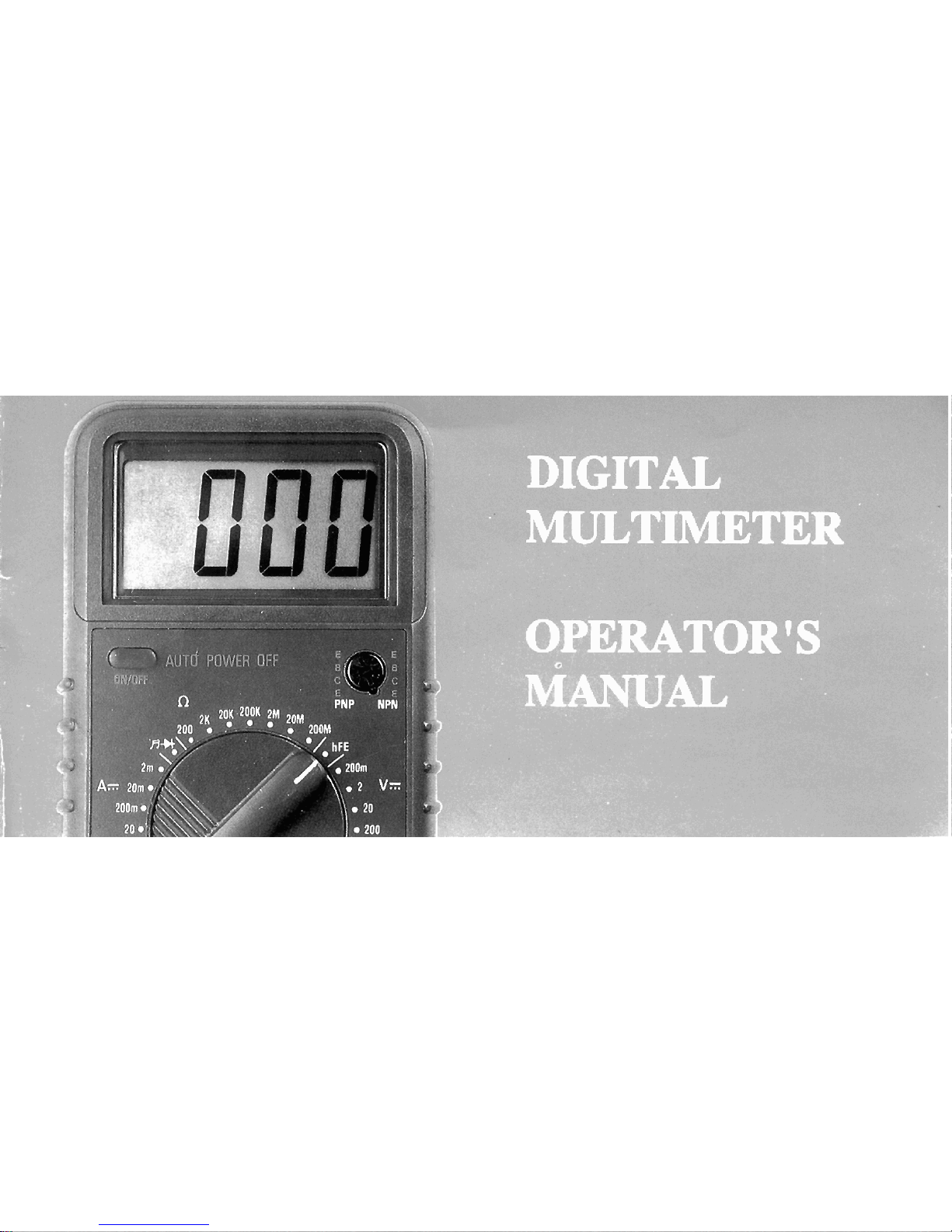
PDi DM62 User manual

CONTENTS PAGE
1
.
Safety Information
1
.
1
Preliminary
1.2 During Use
1.3 Symbols
1.4 Maintenance
2
.
Description
3
.
Operating Instruction
3.1 Measuring Voltage
3.2 Measuring Current
3.3 Measuring Resistance
3.4 Testing Diode

3.5
Testing Transistor
.......................................................................
12
3.6
Continuity Test
.......................................................................
12
4
.
Specifications
.......................................................................
13
5
.
Accessories
.......................................................................
20
5.1
Supplied with the meter
.......................................................................
20
5.2
How to use the holster'
.......................................................................
20
6
.
Battery
&
Fuse Replacement
.......................................................................
22
1.
SAFETY INFORMATION
This multimeter has been designed according to IEC-1010 concerning electronic measuring
instruments with an overvoltage category (CAT
II)
and pollution
2.
Follow all safety and operating instructions to ensure that the meter is used safely and is kept
in good operating condition.
1.1
PRELIMINARY
When using the meter, the user must observe all normal safety rules concerning:
-
Protectionagainst the dangers of electrical current.
-
Protection of the meter against misuse.
Full compliance with safety standards can be guaranteed only if used with test leads
supplied. If necessary, they must be replaced with the same model or same electric ratings.
Measuring leads must be ingood condition.

1.2
DURING USE
Never exceed the protection limit values indicated in specifications for each range of
measuiement.
When the meter is linked to a measurement circuit, do not touch unused terminals.
a
When the value scale to be measured is unknown beforehand, set the range selector at the
highest position.
Before rotating the range selector to change functions, disconnect test leads from the circuit
under test.
When carrying out measurements on
TV
or switching power circuits, always remember that
there may be highamplitude voltages pulses at test points which can damage the meter.
Never perform resistance measurements on live circuits.
Always be careful when working with voltages above
60V
dc or
30V
ac rms. Keep fingers
behind the probe barriers while measuring.

1.3
SYMBOLS
Important safety information, refer to the operating manual.
Dangerous voltage may be present.
8
Earth ground.
Double insulation (Protection class
11).

1.4
MAINTENANCE
Before opening the meter, always disconnect test leads from all sources of electric current.
For continue protection against fire, replace fuse only with the specified voltage and current
ratings:
F1:
F
2Al250V F2:
F
10A1250V
If any faults or abnormalities are observed, the meter can not be used any more and it has
to be checked out.
Never use the meter unless the back cover is in place and fastened fully.
To clean the meter, use a damp cloth and mild detergent only, do not use abrasives or
solvents on it.
2.
DESCRIPTION
This meter is a portable professional measuring instrument with
3%
digit LCD, capable of
performing functions:
-
DC voltage measurement,
5
ranges from 200mV to 1000V
-
AC voltage measurement,
5
ranges from 200mV to 700V
-
DC current measurement,
7
ranges from 20pA to 10A
-
AC current measurement,
6
ranges from 200pA to 10A
-
Resistance measurement,
7
ranges from 200Q to 200MQ
-
Diode test
-
Transistor test
-
Audible continuity test
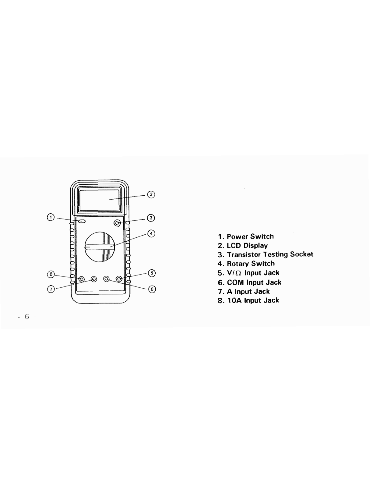
1.
Power Switch
2.
LCD Display
3.
Transistor Testing Socket
4.
Rotary Switch
5.
VlhZ
lnput Jack
6.
COM
lnput Jack
7.
A
lnput Jack
8.
10A
lnput Jack
2.1
FUNCTIONAND RANGE SELECTOR
There are
8
functions and
32
ranges provided. A rotary switch is used to select functions as
well as ranges.
2.2
POWER SWITCH
A
push-push switch isused to turn the meter on or off.
To extend the battery life, Auto Power-Off function is provided(0ptional). The meter will be
turned off automatically within around
40
minutes. To turn on the meter again, push the power
switch to release it and then push it once more.
2.3
INPUT JACKS
This meter has four input jacks that are protected against overload to the limits. During use,
connect the black test lead to the
COM
jack and the red test lead as shown below:

Current ranges are protected
by
fuses
Function
200mV
V:/V-
a
fi*
Ar/A-
10A
Red Lead Connection
V
/
R
via
VIR
V
/
R
A
10A
Input Limits
250V
dc or rms ac
1000V
dc or
700V
rms ac(sine)
250V
dc or rms ac
250V
dc or rms ac
2A
dc or rms ac
10A
dc or rms ac
-
3.
OPERATING INSTRUCTION
3.1
MEASURING VOLTAGE
1. Connect the black test lead to the COM jack and the red test lead to the VIC2 jack.
2.
Set the rotary switch at the desired
V
.I
or
V
-
range position and cormect test leads across
the source or load under measurement.
3.
Read LCD display. The polarity of red connection will be indicated when making a dc
measurement.
4.
When only the figure
"
1"
is displayed,
it
indicates overrange situation and the higher range
has to be selected.
3.2
MEASURING CURRENT
1.
Connect the black test lead to the COM jack and the red test lead to the A jack for a
maximum of
2A.
For a maximum of IOA, move the red lead to the 10Ajack.
2.
Set the rotary switch at desired
A
.:
or
A
-
range position and connect test leads in series
with the load under measurement.
3.
Read LCD display. The polarity of red lead connection will be indicated when making a DC
measurement.
4.
When only the figure
"1"
displayed, it indicates overrange situation and the higher range has
to be selected.
3.3
MEASURING RESISTANCE
1.
Connect the black test lead to the COM jack and the red teas lead to the
Via
jack.
(NOTE:
The polarity of the red lead connection is positive
"
+
")
2.
Set the rotary switch at desired Cl range position and connect test leads across the
resistance under measurement. Read LCD display.
NOTE:
1.
For resistance above
1
MCl, the meter may take a few seconds to stabilize reading.
2.
When the input is not connected, i.e. at open circuit, the figure
"1"
will be displayed for the
overrange condition.
3.
When checking in-circuit resistance, be sure the circuit under test has all power removed
and all capacitors are fully discharged.
4.
At 200MR range display is
1
Ocounts when test leads are shorted. These counts have to be
subtracted from measuring results. For example, when measuring 100M
R
resistance, the
reading will be
101
.O and the correct measuring result should be 101.O-1.0
=
1
0O.OMR.
3.4
TESTING
DIODE
1.
Connect the black test lead to the COM jack and the red test lead to the VIR jack. (NOTE:
The polarity of red lead connection is positive
"
+
")
2.
Set the rotary switch atuposition and connect the red lead to the anode, the black lead to
the cathode of the diode under testing. The meter will show the approx. forward voltage
drop of the diode. If the lead connection is reversed, only figure "1" will be displayed.

3.5
TESTING TRANSISTOR
1.
Set the function switch at hFE position.
2. Identify whether the transistor is NPN or PNP type and locate emitter, base and collector
lead. Insert leads of the transistor to be tested into proper holes of the testing socket on the
front panel.
3.
LCD
display will show the approximate hFE value at the test condition of base current
10pA
and Vce 3.2V.
3.6
CONTINUITY TEST
1.
Connect the black test lead to the COM jack and the red test lead to the V/njack.
2. Set the rotary switch at
fi
positionand connect test leads across two points of the circuit
under testing. If continuity exists(i.e., resistance less than about
70
),
built-in buzzer will
sound.
4.
SPECIFICATIONS
Accuracy is specified for a period of one year after calibration and at 18OC to 28OC (64OF to
82OF) with relative humidity to 80%.
4.1
GENERAL
Max. Voltage Between Terminals and Earth
Ground
Fuse Protection
Power Supply
Display
Measuring Method
Overrange lndication
Polarity lndication
Low Battery lndication
Operating Temperature
1000V dc or 700V rms ac (sine)
A:
F 2A1250V 10A: F 10A1250V
9V battery, NEDA 1604or 6F22
LCD,
1999counts max., updates 2-31sec
Dual-slope integration AID converter
"
1
"
displayed only
"
-
"
displayed automatically
"
"
displayed

Storage Temperature
Dimension
Weight
-lO°C to 50°C (lO°F to 122OF)
91
x
189
x
31.5mm
3109 (Including battery)
4.2
DC
VOLTAGE
Input Impedance: 1OMR
-
14
-
Range
200mV
2V
20V
2OOV
1OOOV
Resolution
O.lmV
I
mV
10mV
0.1V
1V
Accuracy
+
0.5% of rdg
+
1 digits
+
0.5% of rdg
+
1 digits
k
0.5% of rdg
+
1 digits
+
0.5% of rdg
k
1 digits
+
0.8%
of
rdg
+
2 digits

4.3
AC
VOLTAGE
Input Impedance: 10Mn
Frequency Range: 40to 400Hz
Response: Average, calibrated in rms of sine wave
Accuracy
+
1.2% of rdg
k
3
digits
+
0.8% of rdg
k
3
digits
k
0.8% of rdg
2
3
digits
2
0.8% of rdg
*
3
digits
+
1.2% of rdg
k
3
digits
Range
200mV
2V
20V
200V
700V
Resolution
0.1mV
I
mV
10mV
0.1V
1V

4.4
DC
CURRENT
Overload Protection:
F
2A fuse for 20pA
to
2A
ranges,
F
10A fuse for 10A range.
-
16
-
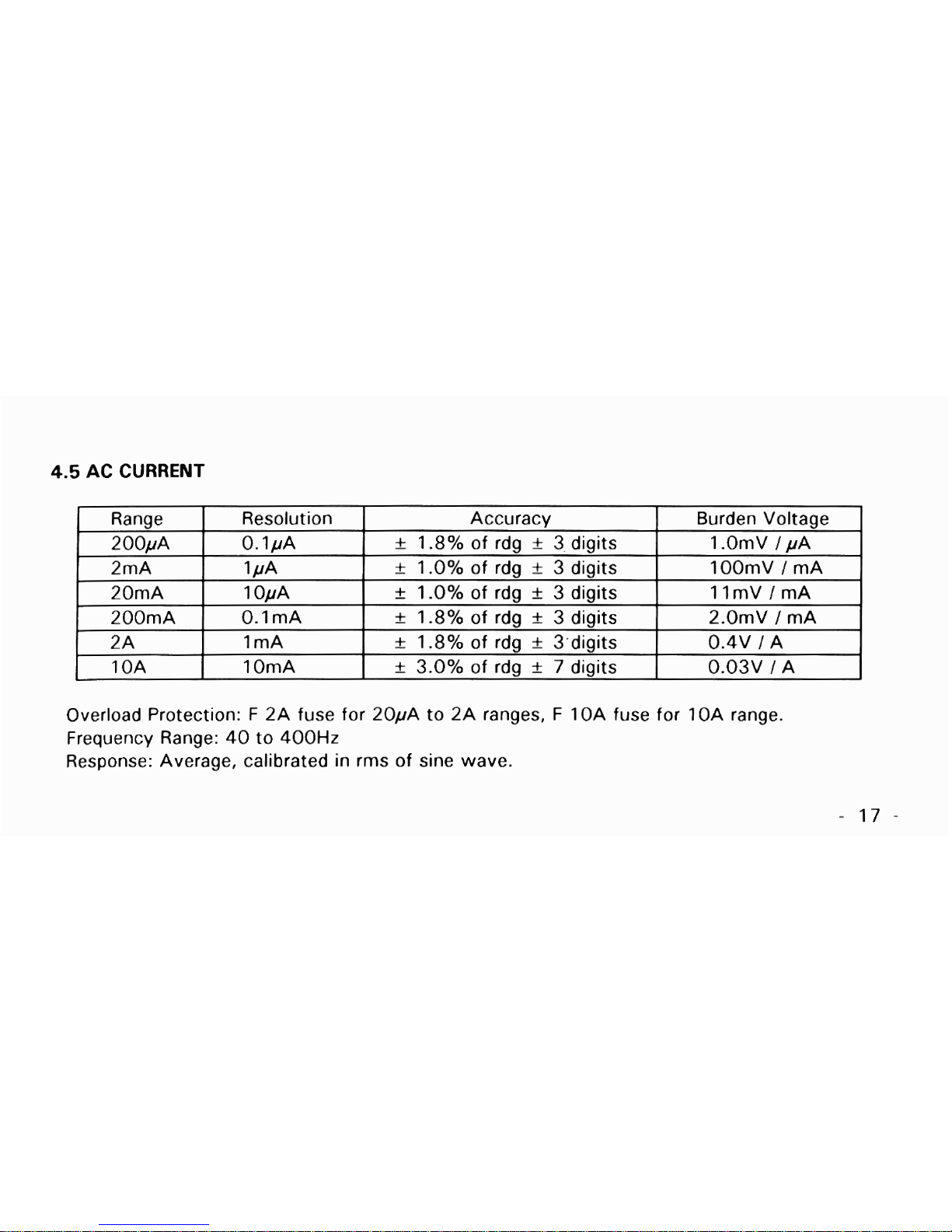
4.5
AC CURRENT
Overload Protection:
F
2A fuse for 20pA to 2A ranges,
F
10Afuse for 10A range.
Frequency Range: 40to 400Hz
Response: Average, calibrated in rms of sine wave.
Range
200pA
2mA
20mA
200mA
2A
10A
Accuracy
+
1.8% of rdg
+
3 digits
+
1.O% of rdg
+
3 digits
+
I
.O% of rdg
+
3
digits
+
1.8% of rdg
+
3
digits
+
1.8% of rdg
*
3,digits
k
3.0% of rdg
+
7
digits
Resolution
0.1pA
1PA
10pA
O.lmA
I
mA
10mA
Burden Voltage
1
.OmV
I
pA
100mV
I
mA
IlmVImA
2.0mV
I
mA
0.4V
I
A
0.03V 1A
Table of contents
Other PDi Multimeter manuals


