METIEC MT1100 Specification sheet

HCLH/SOP-YF-072-115
Data Transceiver and & Power Monitoring Series
MT1100
Operation and Installation Manual

A1-MT1100
1
[Manufacturer]: Wuhan Huchuang Union Technology Co., Ltd.
[Production Address]: No.1 Workshop, 1F, Building B10, Wuhan Hi-Tech Medical Device Park, No. 818 Gaoxin
Avenue, East Lake Hi-Tech Development Zone, Wuhan, Hubei, China
[After-Sales Service Unit]: Wuhan Huchuang Union Technology Co., Ltd.
Date ofApproval and Revision: January 21, 2021

A1-MT1100
2
Contents
1 Overview .................................................................................................................................................................3
1.1 Operation Instructions of Manual.................................................................................................................3
1.2 Overview ......................................................................................................................................................3
1.3 Environmental Requirements .......................................................................................................................3
1.4 Environmental Protection Instructions .........................................................................................................4
2 Structure Features and Equipment Parameters........................................................................................................5
2.1 Structure Features.........................................................................................................................................5
2.2 Equipment Parameters..................................................................................................................................8
3 Basic Operation Instructions....................................................................................................................................9
3.1 Installation Method.......................................................................................................................................9
3.1.1 Laid Flat.............................................................................................................................................9
3.1.2 Wall-Mounting...................................................................................................................................9
3.2 Power-On for Use...................................................................................................................................... 10
3.3 Main Interface Instructions........................................................................................................................ 10
3.4 System Information ................................................................................................................................... 11
3.5 Parameter Setting....................................................................................................................................... 12
3.5.1 Enter Setting Interface.................................................................................................................... 12
3.5.2 "1.SET DATE TIME"..................................................................................................................... 13
3.5.3 "2.SET IP/PORT" ........................................................................................................................... 13
3.5.4 "3.SET WIFI" ................................................................................................................................. 14
3.5.5 "4.SETAPN".................................................................................................................................. 15
4 Precautions............................................................................................................................................................ 16
5 FCC Statement................................................................................................................................................... 17

A1-MT1100
3
1Overview
1.1 Operation Instructions of Manual
1.1.1 It is not allowed to print or disclose any content of this Manual, including pictures and audio
products, under any name without the consent of Huchuang Union;
1.1.2 The equipment operator may copy some sections of this Operation Manual for internal use only,
such as for instructing the user how to deal with emergencies. These sections are clearly listed in
the catalogue of this manual;
1.1.3 Wuhan Huchuang Union Technology Co., Ltd. reserves the copyright of the Manual. The manual
contains the information protected by copyright laws. No part of the Manual is allowed to be
copied and sent to the users without the prior written permission of the copyright holder;
1.1.4 The contents of the Manual are subject to change without prior notice.
1.2 Overview
As a data transmitter and transmitter host monitored by the laboratory, MT1100 can receive local
wireless data and transmit the data to the cloud server via 4G. In addition, MT1100 also has WIFI function,
and can transmit the received wireless data to the local server through WIFI after being connected to the
specified WIFI, and is suitable for local networking. Besides, MT1100 can be connected to MT500 devices,
eight MT500 devices at most;
MT1100 is equipped with a rechargeable lithium battery and can give power failure alarm and
continue to run for more than 8 hours after the adapter is disconnected with the power supply.
1.3 Environmental Requirements
1.3.1 Only for indoor use, no high temperature, moisture, water or dust;
1.3.2 Atmospheric pressure: 70kPa~105kPa; Working ambient temperature: 0℃~+50℃;

A1-MT1100
4
1.3.3 Storage ambient temperature: 0℃~+50℃; relative humidity in the working environment: ≤80%
(non-condensing);
1.3.4 Power adapter (input:AC100V ~ 240V, 50/60Hz; output: 5V, 2.1A, 10.5W);
1.4 Environmental Protection Instructions
1.4.1 MT1100 device contains reusable materials, and its components can be recycled after being cleaned
and sterilized.
1.4.2 During recycling and handling MT1100 device, it is recommended that the company's technical
personnel dismantle it and recycle it according to different waste groups;
1.4.3 According to national regulations, the compositions of the main raw materials of MT1100
equipment shall be are shown in (Table 1).
Table 1 Compositions of Main Raw Materials of MT1100
Name
Composition
Casing
ABS+PC
Baseplate
Sheet metal
Battery
Lithium battery
PCB
Including electrical components

A1-MT1100
5
2Structure Features and Equipment Parameters
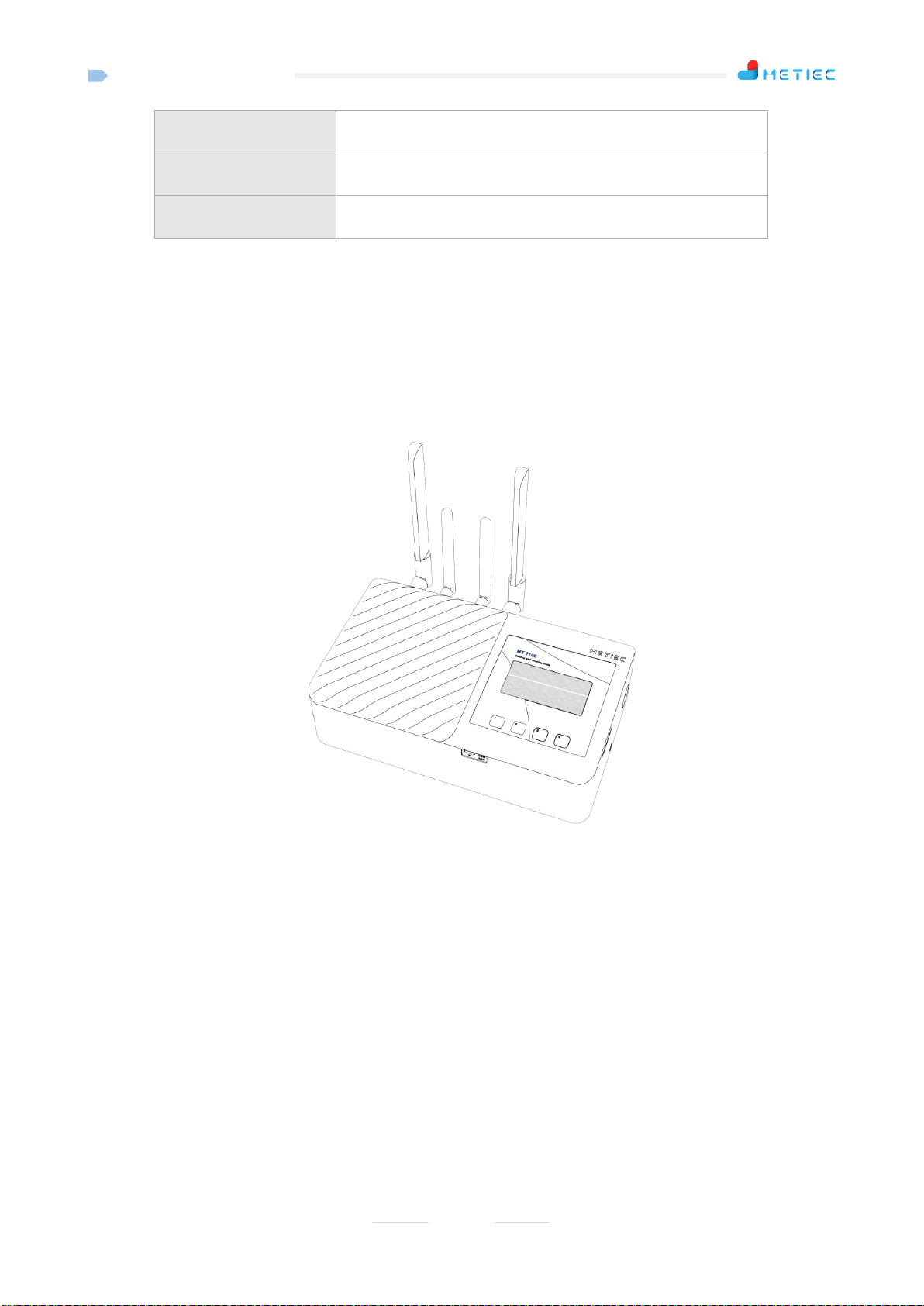
2.1 Structure Features
a) Data Display Screen:
Displays the current states and the current received data of the device.
b) Keys:
Push-type buttons; set or modify the equipment parameters through button operations.
a
b

A1-MT1100
6
c
d
e
f
g
i
j
k
h
l

A1-MT1100
7
c) Upgrade Debugging Port:
Micro USB interface; it has 2 functions: Firstly, it can be used for program upgrade: The special USB
cable customized by the company is used for upgrading program; secondly, it is used to modify
parameters: The special USB cable customized by the company shall be used for modifying
parameters; it needs to work with the modification software of " Huchuang Union Wireless Slaver
Debugging Platform.exe".
d) Reset Button (Pin-socket type).
Press this button to forcibly restart the equipment (the factory setting shall not be reset) when the
equipment breaks down.
e) Power toggle switch:
The device can be powered ON normally only when the toggle switch is turned to ON position.
f) Charging port:
Connected with a 5V/2Apower adapter.
g) Ethernet port:
The device can be directly connected with MT500 through the crossover network cable; if the device
is connected with multiple MT500 devices, then it must be connected with a switch.
h) SIM card holder:
Applicable for standard SIM cards of China Mobile, China Unicom and China Telecom.
i) 4G antenna interface:
Connected with external antenna of 4G Total Communication.
j) 433MHz antenna interface:
Connected with 433 MHz external antenna.

A1-MT1100
8
k) 433MHz antenna interface:
Connected with 433 MHz external antenna.
l) WIFI antenna interface:
Connected with WIFI external antenna.
2.2 Equipment Parameters
Table 2 MT1100 Parameters
Item
Parameter
Overall dimensions
205mm*126mm*55.6mm
Weight
820g
Power supply mode
DC5V/2A
Battery specification
Two 3.7V 18650 batteries in parallel, 5000mAh
Battery life
3~5 years
Data upload frequency
Real-time
Adapter power failure
detection
Uploads the power failure status at once
Local alarm mode
Audible and visual alarm
Display screen
2.42 inches OLED
Battery endurance
> 8 hours (the power supply is cut off after the batter is fully
charged)
SIM card
Standard SIM card
WIFI work frequency
2.4G
WIFI transmission
method
TCP/ IP client
Local WIFI work
frequency
433Mhz
Local wireless
transmission distance
1200 m in open area, 1000 m in streets, about 300 m inside
buildings under the transmission rate of 10Kbps
TCP/IP transmission
interface
RJ45 (supports 8 clients at most)
Storage temperature
0℃~+50℃
A1-MT1100
9
Operating temperature
+0℃~+50℃
Humidity
≤80% (Non-condensing)
Accessories
DC5V adapter, SIM card
3Basic Operation Instructions
3.1 Installation Method
3.1.1 Laid Flat
Choose a fairly empty space and keep it laid flat on the desktop of 20cm away from the human body (the
default installation method).As shown in the following figure.
Note: Try to keep the antenna away from metal objects; otherwise the transmission of wireless signals
will be affected.
3.1.2 Wall-Mounting
Select a relatively open smooth wall, paste 4 pieces of MT1100 special magic tapes on the wall, and
then paste another 4 pieces of MT1100 special magic tapes on the baseplate of MT1100, and then stick
magic tapes together.
Note: Try to keep the antenna away from metal objects; otherwise the transmission of wireless signals
will be affected.

A1-MT1100
10
3.2 Power-On for Use
Step 1: Turn the power toggle switch to "ON" position, at the moment, the equipment will start up
automatically (with built-in chargeable lithiumbattery, the display screen will be on, and the buzzer will
give a short beep; Step 2: Connect the device with the external 5V adapter.
Note: If the device needs to be connected with MT500, the IP address of the device shall be set in
advance, and then it shall be connected with MT500 through a crossover network cable.
3.3 Main Interface Instructions
Key 1: UP key
Key 2: DOWN key
Key 3: OK key
Key 4: Menu button
Interface:
The main interface will pop up after the device is started up. As shown in the following figure:
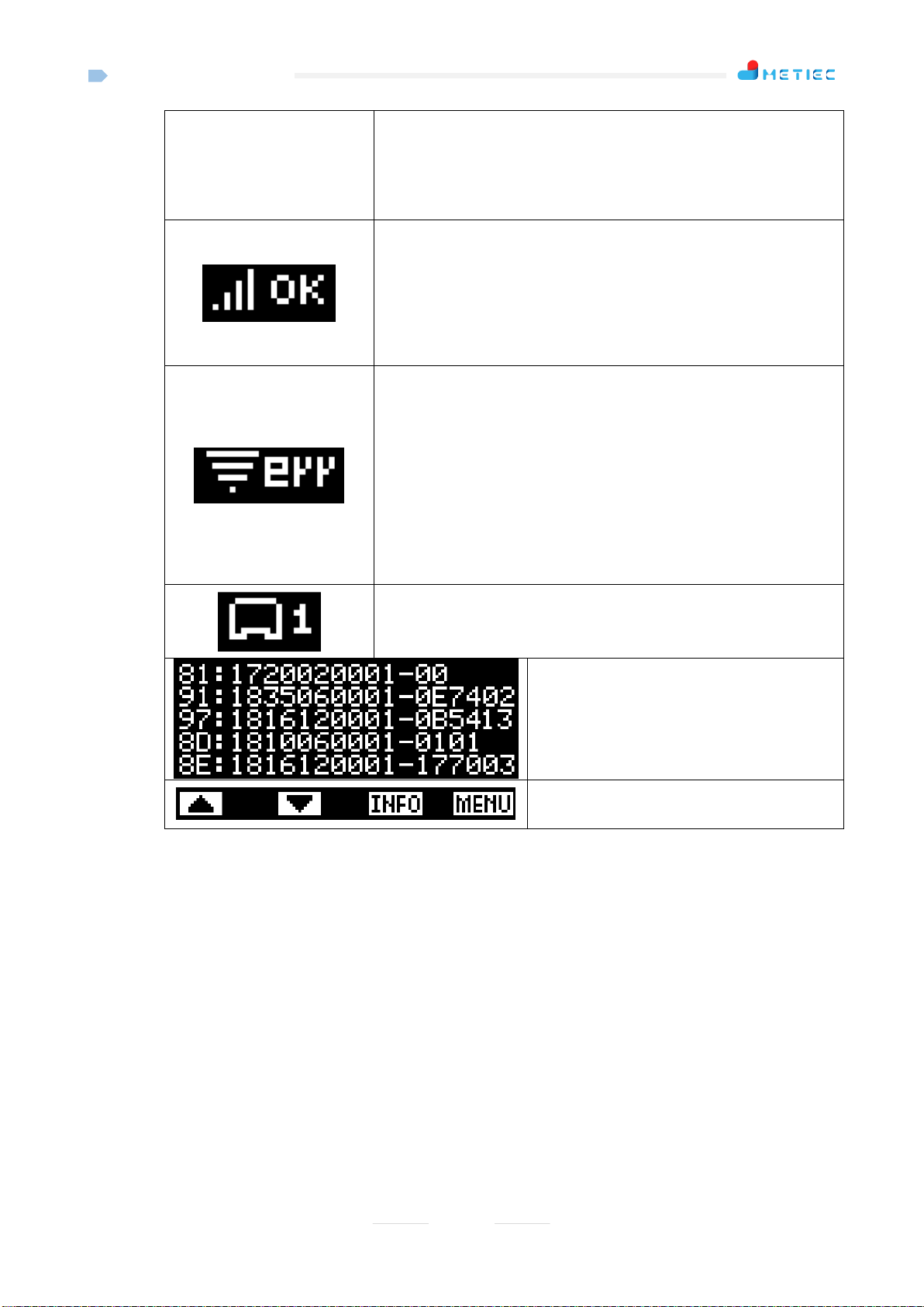
Display Instructions:
Current time: hour: minute
The power supply status of the adapter is shown as follows: "OK"
indicates that the power supply of the adapter is normal; "ERR"
Key 1
Key 2
Key 3
Key 4
A1-MT1100
11
indicates that the power supply of the adapter is abnormal, and there is
an audible and optical alarm (sound: The buzzer beeps; light: the icon
blinks);
4G network signal strength and connection status, strength of full
grids (4 grids) signal; "OK" means that the device is normally
connected to the cloud server; "err" means that the device is connected
to the cloud server abnormally;
WIFI signal strength and connection status, strength of full grids (4
grids) signal; "OFF" indicates that the WIFI function is disabled;
"OK" means that the device is connected to the local server normally;
"link" indicates that the device is connected to the WIFI successfully;
"err" means that the device is connected to the local server
abnormally;
Number of TCP clients successfully connected (number of MT500
devices), 8 at most;
Dynamically refresh the wireless data
received;
Button prompt;
Operation Instructions of Buttons:
Key 1: "▲" key: No function (disabled);
Key 2: "▼" key: No function (disabled);
Key 3: "INFO" key: Press this key to enter "System information interface" to view the relevant
information on the equipment;
Key 4: "MENU" key: Press this key to enter "Setting interface" to set the equipment parameters;
3.4 System Information
After the equipment is normally started up and enters the main interface, you can press the "INFO"
button (Key 3) on the main interface to enter the "System information interface", as shown in the picture
below:

A1-MT1100
12
Display Instructions:
"Model" in Row 1
Equipment model;
"SN" in Row 2
Unique serial number of equipment;
"APN" in Row 3
4G network connectedAPP of equipment;
"MAC" in Row 4
MAC address of Ethernet for equipment;
"WIFI" in Row 5
Local server address and port of WIFI connection;
"Version" in Row 6 and 7
Software/ hardware version of equipment;
Operation Instructions of Buttons:
Key 1: The system returns to the main interface when the key is pressed;
Key 2: The system returns to the main interface when the key is pressed;
Key 3: The system returns to the main interface when the key is pressed;
Key 4: The system returns to the main interface when the key is pressed;
3.5 Parameter Setting
3.5.1 Enter Setting Interface
After the equipment is normally started up and enters the main interface, you can press the "MENU"
button (Key 4) on the main interface to enter the "Setting interface" which include 4 items. As shown in
the following figure:
A1-MT1100
13
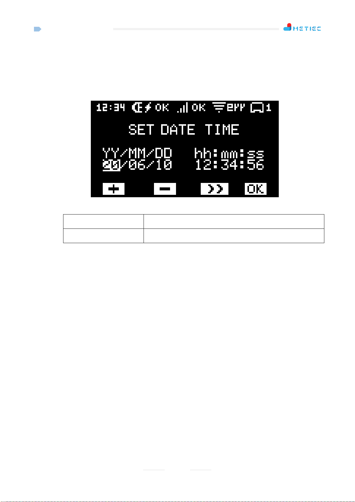
3.5.2 "1.SET DATE TIME"
Note: This option is used for setting the current operating date and time of the equipment;
Select "1.SET DATE TIME" on the setting menu, and then press the "OK" button (Key 3) to enter
the setting interface.As shown in the following figure:
Parameter Description:
“YY/MM/DD”
Set date (year, month, day);
“hh:mm:ss”
Set time (hour: minute: second);
Operation Instructions of Buttons:
Key 1- "+" key: Press this button to add the current set value by 1;
Key 2- "-" key: Press this button to reduce the current set value by 1;
Key 3- ">>" key: When you press the button, the cursor will move to the next set value;
Key 4- "OK" key: When you press the button, the system will automatically save parameters and return to
the setting interface.
3.5.3 "2.SET IP/PORT"
Note: This option is used to set the parameters of the device, including the default gateway, subnet
mask, IP address, port and other parameters of the local Ethernet;
Select "2.SET IP/PORT" on the setting menu, and then press the "OK" button (Key 3) to enter the
setting interface.As shown in the following figure:

A1-MT1100
14
Parameter Description:
"Defa" in Row 1
Default gateway of equipment;
"Mask" in Row 2
Subnet mask of equipment;
"IP" in Row 3
Local IP address of equipment; (if it is connected with MT500, the
MT500 needs to point at the IP address)
"Port" in Row 4
Local port of equipment;
Operation Instructions of Buttons:
Key 1- "+" key: Press this button to add the current set value by 1; besides, the key can be pressed and
held;
Key 2- "-" key: Press this button to reduce the current set value by 1; the key can be pressed and held;
Key 3- ">>" key: When you press the button, the cursor will move to the next set value;
Key 4- "OK" key: When you press the button, the system will automatically save parameters and return to
the setting interface.
3.5.4 "3.SET WIFI"
Note: This option is to set the parameters related to the WIFI function: WIFI function ON/ OFF, IP
port of WIFI connection server, WIFI connection name, WIFI connection password;
Select "3.SETWIFI" on the setting menu, and then press the "OK" button (Key 3) to enter the setting
interface.As shown in the following figure:

A1-MT1100
15
Parameter Description:
"WIFI" in Row 1
WIFI function enable/ disable: "ON" indicates that the WIFI function
is enabled, and "OFF" indicates that the WIFI function is disabled;
"IP" in Row 2
Local server IP address and port of WIFI connection;
"SSID" in Row 3
Indicates the name of the WIFI connection; the device will
automatically scan the 10 WIFI devices with the strongest signal;
"PWM" in Row 4
Indicates the password for WIFI connection, containing only digits
and letters, 14 bits at most; insufficient ones replaced by "*";
Operation Instructions of Buttons:
Key 1- "+" key: Press this button to add the set value;
Key 2- "-" key: Press this button to reduce the set value;
Key 3- ">>" key: When you press the button, the cursor will move to the next set value;
Key 4- "OK" key: When you press the button, the system will automatically save parameters and return to
the setting interface.
3.5.5 "4.SETAPN"
Note: This option is to set the APN of 4G network, and select the corresponding APN according to
the SIM carrier type;
Select "4.SETAPN" on the setting menu, and then press the "OK" button (Key 3) to enter the setting
interface.As shown in the following figure:

A1-MT1100
16
Parameter Description:
"CM" in Row 1
Indicates the APN used for the SIM card of China Mobile
Communication Corporation;
"CU" in Row 2
Indicates the APN used for the SIM card of China Unicom;
"CT" in Row 3
Indicates the APN used for the SIM card of China Telecom.
Operation Instructions of Buttons:
Key 1: "▲" key: Press this button to select the previous option;
Key 2: "▼" key: Press this button to select the next option;
Key 3: "OK" key: When you press the button, the system will automatically save parameters and return to
the setting interface;
Key 4: "EXIT" key: When you press the button, the system does not save parameters but directly returns
to the setting interface.
4Precautions
The local wireless transmission distance of MT1100 is limited and should generally not exceed 3 rooms. If
the walls of the rooms are made of metal materials, it is better to install one device in each room.
MT1100 is not waterproof, so the equipment shall not directly contact with liquid water.
MT1100 is equipped with polymeric battery and shall be not allowed to contact the high temperature
environment to prevent battery damage;
MT1100 is directly connected with MT500 through crossover network cables;
Metal affects wireless signals, therefore, the antenna shall be not blocked by metal objects around during
installation;
Lithium batteries have a certain service life and it is recommended to replace the batteries once every 3
years;

A1-MT1100
17
5FCC Statement
15.19 Labeling requirements.
This device complies with part 15 of the FCC Rules. Operation is subject to the following two conditions: (1)
This device may not cause harmful interference, and (2) this device must accept any interference received,
including interference that may cause undesired operation.
15.21 Information to user.
Any Changes or modifications not expressly approved by the party responsible for compliance could void the
user's authority to operate the equipment.
15.105 Information to user.
This equipment has been tested and found to comply with the limits for a Class B digital device, pursuant to
Part 15 of the FCC Rules. These limits are designed to provide reasonable protection against harmful
interference in a residential installation. This equipment generates uses and can radiate radio frequency
energy and, if not installed and used in accordance with the instructions, may cause harmful interference to
radio communications. However, there is no guarantee that interference will not occur in a particular
installation. If this equipment does cause harmful interference to radio or television reception, which can be
determined by turning the equipment off and on, the user is encouraged to try to correct the interference by
one or more of the following measures:
-- Reorient or relocate the receiving antenna.
-- Increase the separation between the equipment and receiver.
-- Connect the equipment into an outlet on a circuit different from that to which the receiver is connected.
-- Consult the dealer or an experienced radio/TV technician for help.

A1-MT1100
18
Specific Absorption Rate (SAR) information:
This product meets the government's requirements for exposure to radio waves. The guidelines are based on
standards that were developed by independent scientific organizations through periodic and thorough
evaluation of scientific studies. The standards include a substantial safety margin designed to assure the safety
of all persons regardless of age or health.
FCC RF Exposure Information and Statement The SAR limit of USA (FCC) is 1.6 W/kg averaged over one
gram of tissue. This device was tested for typical body-worn operations with the back of the handset kept
10mm from the body. To maintain compliance with FCC RF exposure requirements, use accessories that
maintain a 10mm separation distance between the user's body and the back of the handset. The use of belt
clips, holsters and similar accessories should not contain metallic components in its assembly. The use of
accessories that do not satisfy these requirements may not comply with FCC RF exposure requirements, and
should be avoided.
Body-worn Operation
This device was tested for typical body-worn operations. To comply with RF exposure requirements, a
minimum separation distance of 10mm for body worn must be maintained between the user’s body, including
the antenna. Third-party belt-clips, holsters, and similar accessories used by this device should not contain
any metallic components. Body-worn accessories that do not meet these requirements may not comply with
RF exposure requirements and should be avoided. Use only the supplied or an approved antenna.

A1-MT1100
19
Wuhan Huchuang United Technology Co., Ltd.
Address: No.1 Workshop, 1F, Building B10, Wuhan Hi-Tech Medical Device Park, No. 818 Gaoxin
Avenue, East Lake Hi-Tech Development Zone, Wuhan, Hubei, China
Table of contents


