Yaesu FT-250R User manual

OPERATING MANUAL
FT-250R
VERTEX STANDARD CO., LTD.
4-8-8 Nakameguro, Meguro-Ku, Tokyo 153-8644, Japan
VERTEX STANDARD
US Headquarters
10900 Walker Street, Cypress, CA 90630, U.S.A.
YAESU UK LTD.
Unit 12, Sun Valley Business Park, Winnall Close
Winchester, Hampshire, SO23 0LB, U.K.
VERTEX STANDARD HK LTD.
Unit 1306-1308, 13F., Millennium City 2, 378 Kwun Tong Road,
Kwun Tong, Kowloon, Hong Kong
VERTEX STANDARD (AUSTRALIA)PTY., LTD.
Tally Ho Business Park, 10 Wesley Court, East Burwood, VIC, 3151

Introduction .......................................... 1
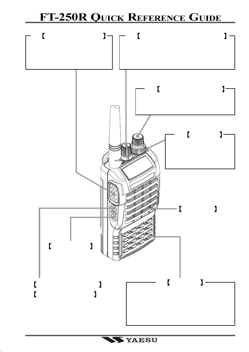
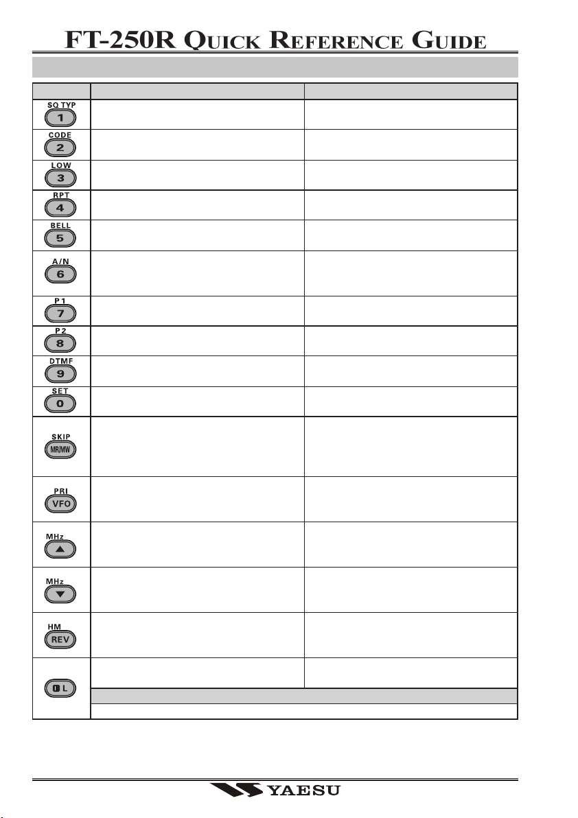
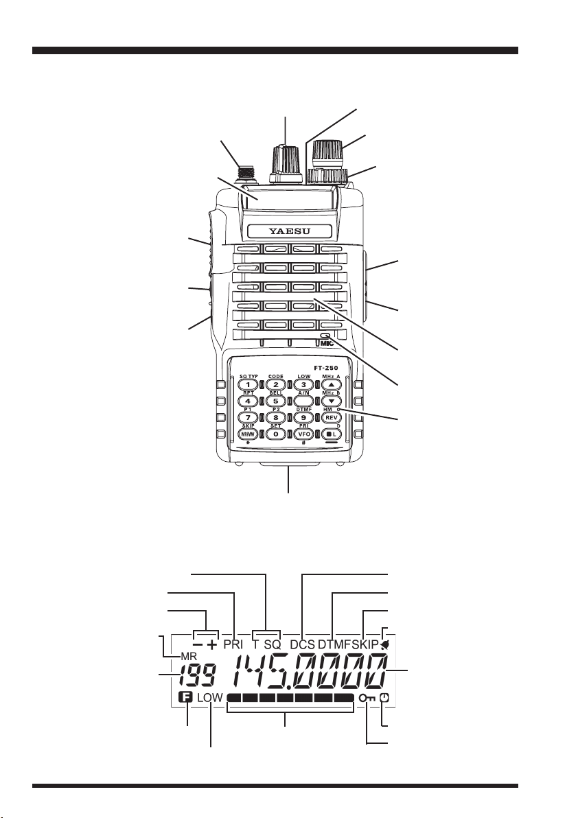
Controls & Connectors ........................ 2
Accessories & Options .......................... 3
Basic Operation .................................... 4
Battery Pack Installation and Removal ...... 4
Battery Charging ......................................... 4
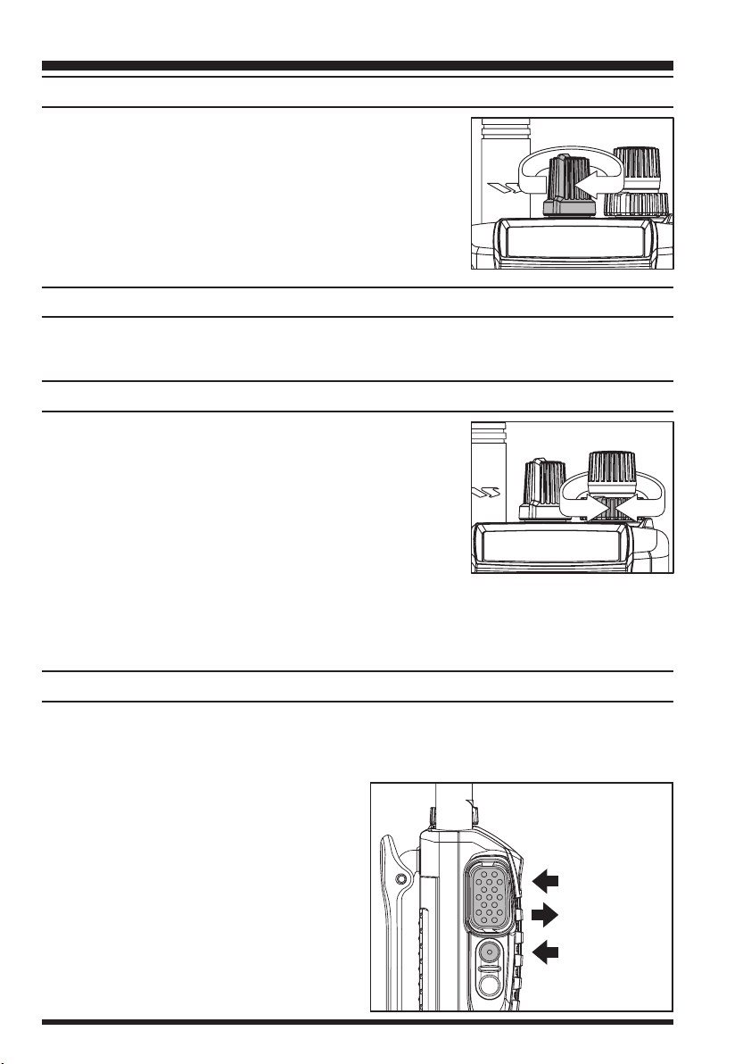
Antenna Installation .................................... 5
Switching Power ON and OFF ................... 6
Adjusting the Volume Level ....................... 6
Squelch Setup ............................................. 6
Transmitting ................................................ 6
Frequency Navigation ................................. 7
Changing the Transmitter Power Level ...... 7
Changing the Channel Steps ....................... 7
Repeater Operation ..................................... 8
Automatic Repeater Shift (ARS) ............ 8
Manual Repeater Shift Activation .......... 8
Setting Repeater Tx Offset ..................... 9
Checking the Repeater
Uplink (Input) Frequency ... 9
Keyboard Locking ...................................... 9
Advanced Operation .......................... 10
VFO Split Mode ....................................... 10
Receive Battery Saver Setup .................... 10
Tx Battery Saver ....................................... 11
Keypad/LCD Illumination ........................ 11
Automatic Power-Off (APO) Feature ....... 12
Checking the Battery Voltage ................... 12
Disabling the BUSY/TX LED .................. 12
Busy Channel Lock-Out (BCLO) ............. 12
Disabling the Key pad Beeper .................. 13
Programming the Key Functions .............. 13
Transmitter Time-Out Timer (TOT) ......... 13
Tone Calling (1750 Hz) ............................ 14
ANI Operation (Automatic
Number Identification) ... 14
CTCSS Operation ..................................... 15
DCS Operation ......................................... 16
Tone Search Scanning .............................. 17
To scan for the tone in use .................... 17
CTCSS/DCS Bell Operation .................... 17
Contents
Memory Operation ............................. 18
Memory Storage ....................................... 18
Storing Independent Trasmit
Frequencies (“Odd Splits”) .... 18
Memory Recall ......................................... 18
Memory Offset Tuning ............................. 19
HOME Channel Memory ......................... 19
Labeling Memories ................................... 19
Masking Memories ................................... 20
Memory Only Mode ................................. 20
Scanning .............................................. 21
Setting the Scan Resume Technique ..... 21
To set the Scan-Resume mode .............. 21
VFO Scanning .......................................... 21
Memory Scanning ..................................... 22
How to Skip (Omit) a Channel
During Memory Scan Operatin ... 22
Programmable (Band Limit)
Memory Scan (PMS) .... 22
Automatic Lamp Illumination
on Scan Stop .... 23
Band Edge Beeper .................................... 23
Smart Search Operation ............................ 23
Setting the Smart Search Mode ............ 24
Storing Smart Search Memories ........... 24
Priority Channel Scanning
(Dual Watch) .... 24
DTMF Operation ................................ 26
Manual DTMF Tone Generation .............. 26
DTMF Autodialer ..................................... 26
To send the telephone number .............. 26
ARTS Operation ................................. 27
Basic ARTS Setup and Operation ............ 27
ARTS Polling Time Options .................... 28
ARTS Alert Beep Options ........................ 28
CW Identifier Setup .................................. 28
To activate the CW identifier ................ 29
Interface of Packet TNCs ................... 30
Reset ..................................................... 30
Cloning................................................. 31
Set Mode .............................................. 32
Specifications ...................................... 39

LOCK KEY
Press and hold in the [F/L] key for
one second to lock all key functions
except the VOL, SQL Knobs, PTT,
T.CALL, and LAMP Switchs.
POWER SWITCH AND VOL KNOB
Rotate the VOL/PWR knob to turn the
radio on and adjust the Audio Volume
Level.
MICROPHONE
TRANSMISSION SWITCH
Speak into the microphone
in a normal voice level while
pressing the PTT switch.
FREQUENCY DIAL KNOB
Rotate the DIAL Knob to select the
operating frequency.
LAMP SWITCH
MONITOR SWITCH (USA)
T.CALL SWITCH (EXP)
SQL KNOB
Adjusts to the point
where the background
noise is muted.

KEY OVERVIEW
Press [F/L]+ Key
Activates the CTCSS or DCS Operation.
Selects the CTCSS tone or DCS code
number.
Selects the desired transmit power out-
put level.
Selects the direction of the uplink fre-
quency shift during repeater operation.
Selects the CTCSS/DCS Bell ringer rep-
etitions.
Toggles the display indication between
“frequency” and the channel’s “Alpha/
Numeric Tag”.
Activates the ARTS feature.
Activates the Smart Search feature.
Selects the DTMF Mode.
Engages the Set (Menu) Mode.
Selects the Memory Scan “Skip” chan-
nel-selection mode.
Activates the Priority (Dual Watch) func-
tion.
Tunes the VFO frequency upward in 1
MHz steps.
Tunes the VFO frequency downward in
1 MHz steps.
Switches to the “Home” (favorite fre-
quency) Channel.
Disables the “Alternate” key function.
Press & Hold Key
Activates the Key Lockout feature.
Press Key
Frequency entry digit “1.”
Frequency entry digit “2.”
Frequency entry digit “3.”
Frequency entry digit “4.”
Frequency entry digit “5.”
Frequency entry digit “6.”
Frequency entry digit “7.”
Frequency entry digit “8.”
Frequency entry digit “9.”
Frequency entry digit “0.”
Sets the frequency control to the
Memory Recall mode.
Activates the “Memory “Tune” mode
while in the Memory Recall mode.
Sets frequency control to the VFO mode.
Toggles the VFO between “VFO A” and
“VFO B” while in the VFO mode.
Increasser the VFO frequency by one
step or moves the memory channel to the
next-highest channel.
Decreases the VFO frequency by one
step or moves the memory channel to the
next-lowest channel.
Reverses the transmit and receive fre-
quencies while working through a re-
peater.
Activates the “Alternate” key function.

FT-250R OPERATING MANUAL 1
The FT-250R is an ultra compact FM hand-held providing up to five watts of RF power
and a wealth of convenient features for the 2m amateur band. The FT-250R has rubber
gasket seals around all external controls and connectors to help keep out dust and rain or
spray, assuring years of reliable operation even in harsh environments.
Sixteen multi-function keys provide the ultimate in programmability, with 199 freely tun-
able memories and two VFOs. All memories store repeater shifts or separate tx/rx fre-
quencies, CTCSS (Continuous Tone Controlled Squelch System) or DCS status. You also
get one instant-recall “Home” channel memory and ten special purpose memories for
limited subband tuning/scanning. Busy channel band or selective memory scanning is
provided along with priority channel monitoring; 1 MHz up/down stepping; ARS (auto-
matic repeater shift) when tuned to repeater subbands; plus a top panel rotary dial for
memory and frequency selection. The keypad serves as a DTMF encoder during transmis-
sion, and up to 9 DTMF memories can store 16 digits each for quick playback of com-
monly used numbers.
The liquid crystal display shows seven frequency digits, memory selection, CTCSS tone
frequency, and includes a bargraph S/PO meter. Yaesu’s power saver system can be set by
the operator for optimum sampling/standby ratio, or can be turned off for packet opera-
tion. And our new APO (Automatic Power Off) system shuts off the transceiver to avoid
dead batteries if you doze off or are called away unexpectedly.
Operation under difficult conditions is simplified by a lamp button illuminating the dis-
play and backlit translucent keypad, diatonically assigned function-dependent keypad beeps.
Please read this manual carefully to gain a full understanding of the features of the
FT-250R.
Introduction

FT-250R OPERATING MANUAL2
Controls & Connectors
Keypad
Microphone
Speaker
EXT DC Jack
MIC/SP Jack
Battery Pack Latch
PTT Button
BUSY/TX Indicator Lamp
SQL Control
DIAL Rotary Selector
Monitor (T.CALL) Button
LAMP Button
LCD (Liquid Crystal Display)
VOL/PWR Knob
ANTENNA Jack
S- and TX Power Meter Auto Power OFF Active
LOCK Feature Active
LOW Power
Alt Key Active
Memory Number
or
VFO Selection
Tone Encoder/Squelch Enabled Digital Coded Squelch
DTMF Memory Mode
Memory Skip
BELL
Priority Channel Scanning
Repeater Shift
Memory Mode
Frequency

FT-250R OPERATING MANUAL 3
ACCESSORIES SUPPLIED WITH THE FT-250R
FNB-83 Ni-MH Battery Pack (7.2 V, 1400 mAh)
PA-38 AC Adapter
CD-30 Desktop Charger
Belt Clip
Antenna
Operating Manual
Warranty Card
AVAILABLE OPTIONS FOR YOUR FT-250R
FNB-83 7.2 V, 1400 mAh Ni-MH Battery Pack
FBA-25A Compact Dry Cell Battery Case for 6 AA-size cells
PA-38 AC Adapter
CD-30 Desktop Charger
MH-34B4B Speaker/Microphone
MH-37A4B Earpiece/Microphone
VC-25 VOX Headset
CT-27 Cloning Cable
E-DC-5B DC Cable w/Noise Filter
E-DC-6 DC Cable; plug and wire only
CN-3 BNC-to-SMA Adapter
CT-44 Microphone Adapter
CSC-77 Soft Case
Availability of accessories may vary: some accessories are supplied as standard per local
regulations and requirements, others may be unavailable in some regions. Check with
your Yaesu dealer for additions to the above list.
Accessories & Options

FT-250R OPERATING MANUAL4
Basic Operation
BATTERY PACK INSTALLATION AND REMOVAL
To install the battery, hold the transceiver with your left hand, so your palm is over the
speaker and your thumb is on the top of the belt clip. Insert the battery pack into the
battery compartment on the back of the radio while tilting the Belt Clip outward, then
close the Battery Pack Latch until it locks in place with a “Click.” To remove the battery,
turn the radio off and remove any protective cases. Open the Battery Pack Latch on the
bottom of the radio, then slide
the battery downward and out
from the radio while unfold-
ing the Belt Clip.
Do not attempt to open any of
the rechargeable Ni-MH
packs, as they could explode
if accidentally short-circuited.
BATTERY CHARGING
If the battery has never been used, or its charge is depleted, it may be charged by connect-
ing the PA-38/CD-30 Desktop Charger.
cInsert the DC plug from the PA-38 AC Adapter into the DC
jack on the bottom side of the CD-30 Desktop Charger, then
plug the PA-38 AC Adapter into the AC line outlet.
dInsert the battery pack into the CD-30 Desktop Charger while
aligning the slots of the battery pack with the guides in the nest
of the CD-30; refer to the illustration below for details on proper
positioning of the pack. If charging with the transceiver at-
tached, turn the transceiver off, and the antenna jack should be
at the left side when viewing the charger from the front.
eIf the battery pack is inserted correctly, the LED indicator will
glow red (Charging).
A fully-discharged pack will be charged completely in
approximately 3 hours.
fWhen charging is completed, the red LED indicator will
change to green (Fully Charged). Disconnect the pack
from the CD-30 Desktop Charger, and unplug the PA-
38 AC Adapter from the AC line outlet.
Tilt the Belt Clip Insert the Battery Pack
Close the
Battery Pack Latch
Align the slots of the battery pack
with the guides in the nest of the
CD-30 Desktop Charger.

FT-250R OPERATING MANUAL 5
Important Notes!
Do not connect an improper AC Adapter. Use only the supplied PA-38 AC Adapter.
Do not charge an improper battery (one not specifically designed for use in the
PA-38/CD-30).
Disconnect the pack from the CD-30 Desktop Charger, and unplug the PA-38 AC
Adapter from the AC line outlet, when charging is completed.
The PA-38 AC Adapter and/or CD-30 Desktop Charger will generate a moderate
amount of heat during the charging process. This is a normal condition.
The PA-38/CD-30 is designed for charging only, and is not designed for operation
(transmission/reception) of the transceiver.
Periodically wipe the charging terminals in the nest in the charger stand, using a dry
cloth, to ensure good connections between the charger and battery.
Caution!!
When charging a battery pack alone (not attached to the transceiver), do not allow any
metal object to short the terminals on top of the pack.
Do not allow any metal objects to short the terminals in the nest of the charger stand,
as a short-circuit could cause overheating of the charger circuitry.
ANTENNA INSTALLATION
The supplied antenna provides good results over the entire frequency range of the trans-
ceiver. However, for enhanced coverage in remote areas, an external mobile or base sta-
tion antenna may prove beneficial.
To install the supplied antenna
Hold the bottom end of the antenna, then screw it onto the
mating connector on the transceiver until it is snug. Do not
over-tighten by use of extreme force.
Notes:
Never transmit without having an antenna connected.
When installing the supplied antenna, never hold the
upper part of the antenna while screwing it onto the
mating connector on the transceiver.
If using an external antenna for transmission, ensure that the SWR presented to the
transceiver is 1.5:1 or lower, to avoid excessive feedline loss.
Basic Operation

FT-250R OPERATING MANUAL6
SWITCHING POWER ONAND OFF
cBe sure the battery pack is installed.
dConnect the antenna to the top panel ANTENNA jack.
eSwitch on the transceiver by rotating the VOL control
clockwise out of the click-stop (a momentary beep will
sound).
ADJUSTING THE VOLUME LEVEL
Rotate the VOL control (immediately to the right of the Antenna) to set the desired audio
level. Clockwise rotation increases the volume level.
SQUELCH SETUP
Set the SQL control fully counterclockwise, rotate the VOL
control out of the click-stop and adjust for a comfortable
volume on the noise or received signal. The BUSY/TX
indicator LED should glow green. If a signal is present,
rotate the DIAL selector on the top panel to a channel where
only noise is heard.
Adjust the SQL control just to the point where the noise is
silenced and the LED is extinguished. If the SQL control is set further clockwise, sensi-
tivity to weak signals will be reduced. Now, whenever a signal reaches the receiver that is
strong enough to open the squelch, the indicator will glow green.
TRANSMITTING
When you wish to transmit, wait until the channel is clear (BUSY/TX lamp off), and
squeeze the PTT switch. During transmission the BUSY/TX indicator glows red, and
relative transmitter power output is indicated graphically along the bottom of the display.
Release the PTT switch to receive.
If using a “B” version (in Europe), press the
T-CALL switch (just below the PTT switch)
to transmit a 1750 Hz tone to access repeat-
ers that require it.
Basic Operation
TX
RX
T-CALL

FT-250R OPERATING MANUAL 7
FREQUENCY NAVIGATION
Press the [VFO(PRI)]button, if necessary, to select the VFO mode. The FT-250R has
two VFOs, labeled “A” and “B,” either of which can be used for all of the procedures
described in this manual. You can change VFOs with the [VFO(PRI)]button at any time.
There are several ways to tune the FT-250R: in selectable channel steps or 1 MHz steps
with the [(MHz)]/ [(MHz)]keys or DIAL knob, and direct keypad frequency entry.
Use the DIAL knob to tune the displayed VFO frequency at the current channel step rate.
You can also press the [(MHz)]/ [(MHz)]keys momentarily to do this.
To change the MHz range of the VFO, you can press the [F/L]key followed by an [(MHz)]
or [(MHz)]key (or turn the DIAL knob). Note the beeps when using the [(MHz)]/
[(MHz)]keys when moving up or down. When done, press [F/L]again, or just wait five
seconds.
You can also enter a frequency directly just by keying in the 10 MHz, 1 MHz and the kHz
digits. Partial entries can be completed using the [VFO(PRI)]key.
Examples:
To enter 146.5200 MHz, press
To enter 146.5000 MHz, press
CHANGING THE TRANSMITTER POWER LEVEL
You can select between a total of three transmitter power levels on your FT-250R. The
exact power output will vary somewhat, depending on the voltage supplied to the trans-
ceiver. With the standard FNB-83 Battery Pack, the power output levels available are:
HIGHHIGH
HIGHHIGH
HIGH: 5 W MIDMID
MIDMID
MID: 2 W LOWLOW
LOWLOW
LOW: 0.5 W
To change the power level:
cPress the [F/L]key, then immediately press the [3(LOW)]key.
dNow rotate the DIAL knob to select “LOWLOW
LOWLOW
LOW”, “MIDMID
MIDMID
MID,” or “HIGHHIGH
HIGHHIGH
HIGH”.
ePress the PTT key to save the new setting and exit to normal operation.
CHANGING THE CHANNEL STEPS
To change a frequency step, follow the procedure below:
cPress the [F/L]key, then immediately press the [0(SET)]key to enter the Set mode.
dRotate the DIAL to select Menu Item #6 (“STEPSTEP
STEPSTEP
STEP”).
ePress the [F/L]key to enable modification of the current setting.
fNow rotate the DIAL knob to select 5, 10, 12.5, 15, 20, 25 or 50 kHz steps.
gPress the PTT key to save the new setting and exit to normal operation.
Basic Operation

FT-250R OPERATING MANUAL8
REPEATER OPERATION
The ARS (Automatic Repeater Shift) feature in the FT-250R provides repeater shift of
the transmit frequency whenever you are tuned to a standard repeater subband (see dia-
gram below). When enabled, a small “–” or “+” will be displayed in the upper left-hand
corner of the display, signifying that repeater shift is active, and closing the push-to-talk
switch changes the display to the (shifted) transmit frequency.
Basic Operation
Automatic Repeater Shift (ARS)
To re-enable ARS:
cPress the [F/L]key, then immediately press the [0(SET)]key to enter the Set mode.
dRotate the DIAL to select Menu Item #2 (“ARSARS
ARSARS
ARS”).
ePress the [F/L]key to enable modification of the current setting.
fNow rotate the DIAL to select “ON” (to enable Automatic Repeater Shift).
gPress the PTT key to save the new setting and exit to normal operation.
Tone Burst
For repeaters using 1750-Hz burst tone access, you can configure the switch below
the PTT to send the access tone when this switch is pressed. See page 14 for details.
Manual Repeater Shift Activation
When a repeater shift is active, either “–” or “+” appears in the display. If neither appears
when tuned to a repeater output frequency, you can activate the shift manually:
cPress the [F/L]key, then immediately press the [0(SET)]key to enter the Set mode.
dRotate the DIAL to select Menu Item #3 (“RPTRPT
RPTRPT
RPT”).
ePress the [F/L]key to enable modification of the current setting.
fRotate the DIAL to select the desired repeater shift direction (-RPT-RPT
-RPT-RPT
-RPT, +RPT+RPT
+RPT+RPT
+RPT or SIMPSIMP
SIMPSIMP
SIMP).
gPress the PTT key to save the new setting and exit to normal operation.

FT-250R OPERATING MANUAL 9
Setting repeater Tx Offset
Although you should keep the repeater offset programmed to that used in your area, you
can change the default repeater offset for special applications:
cPress the [F/L]key, then immediately press the [0(SET)]key to enter the Set mode.
dRotate the DIAL to select Menu Item #4 (“SHIFTSHIFT
SHIFTSHIFT
SHIFT”).
ePress the [F/L]key to enable modification of the current setting.
fRotate the DIAL to select the new shift offset frequency (selectable in 50-kHz incre-
ments only).
gPress the PTT key to save the new setting and exit to normal operation.
Checking the Repeater Uplink (Input) Frequency
It often is helpful to be able to check the uplink (input) frequency of a repeater, to see if the
calling station is within direct (“Simplex”) range.
To do this, just press the [REV(HM)]key momentarily. If Menu Item #20 (“REVREV
REVREV
REV/HMHM
HMHM
HM”)
has been set to “HMHM
HMHM
HM,” you may press the [F/L]key, and then [REV(HM)]key. To return to
the normal uplink/downlink frequency relationship, repeat this step.
KEYBOARD LOCKING
To activate the locking feature, press and hold in the [F/L]key for one second. The “ ”
icon will appear on the LCD. To cancel locking press and hold in the [F/L]key again for
one second.
In order to prevent accidental frequency change or inadvertent transmission, various as-
pects of the FT-250R’s DIAL, keypad and switches may be locked out. You may change
the lockout combinations.
To lock out some or all of the keys:
cPress the [F/L]key, then press the [0(SET)]key to enter the Set mode.
dRotate the DIAL to select Menu Item #32 (“LK MODELK MODE
LK MODELK MODE
LK MODE”).
ePress the [F/L]key to enable setting of the Lock mode (which defines which keys/
functions are to be locked out).
fRotate the DIAL to the desired locking scheme as listed below:
KEYKEY
KEYKEY
KEY: Just the front panel keys are locked out
DIALDIAL
DIALDIAL
DIAL: Just the top panel DIAL is locked out
KK
KK
K+ DD
DD
D (KEYKEY
KEYKEY
KEY + DIALDIAL
DIALDIAL
DIAL) : Both the DIAL and Keys are locked out
PTTPTT
PTTPTT
PTT: The PTT switch is locked (TX not possible)
KK
KK
K+ PP
PP
P (KEYKEY
KEYKEY
KEY + PTTPTT
PTTPTT
PTT) : Both the keys and PTT switch are locked out
DD
DD
D+ PP
PP
P (DIALDIAL
DIALDIAL
DIAL + PTTPTT
PTTPTT
PTT) : Both the DIAL and PTT switch are locked out
ALLALL
ALLALL
ALL: All of the above are locked out
gWhen you have made your selection, press the PTT key momentarily to save the new
setting and resume normal operation.
Basic Operation

FT-250R OPERATING MANUAL10
VFO SPLIT MODE
For working on repeaters with odd splits, or communicating with astronauts on orbiting
space vehicles, it may be necessary to use non-standard splits between the receive and
transmit frequency. If the application is infrequent enough not to warrant the dedication of
a memory channel for this purpose, the “VFO Split” mode may be used. Here is the proce-
dure:
cPress the [VFO(PRI)]key, as needed, to select VFO-A. Set VFO-A for the receiving
frequency (for example, 144.950 MHz).
dNow press the [VFO(PRI)]key, and set VFO-B for the desired transmit frequency
(e.g. 144.750 MHz).
ePress the [VFO(PRI)]key once more to re-establish VFO-A as the “Main” (receive)
VFO.
fPress the [F/L]key, then press the [0(SET)]key, to enter the Set mode.
gRotate the DIAL to select Menu #5 (“V-SPLITV-SPLIT
V-SPLITV-SPLIT
V-SPLIT”).
hPress the [F/L]key, then rotate the DIAL to set this function ON.
iPress the PTT key once to save the new setting and exit to normal operation.
jYou will now be operating in a Split mode. When you press the PTT key to transmit,
you will observe that VFO-A and VFO-B will reverse positions.The VFO selection
indicator “bb
bb
b” will blinks while the transceiver is transmitting, this means that the VFO
Split feature is now activated.
kIf you need to modify the VFO-B (transmit) frequency (for Doppler Shift correction,
etc.), just press the [VFO(PRI)]key, then make the necessary change, then press
[VFO(PRI)]key once more to restore VFO-A to the “receive VFO” position.
lWhen you have finished with Split operation, re-enter the Set mode, and set Menu #5
to OFF.
A split frequency pair set up via the VFO Split feature cannot be stored directly into
memory. You can, however, store odd frequency pairs using a different (slightly simpler)
procedure. See page 18.
RECEIVE BATTERY SAVER SETUP
An important feature of the FT-250R is its Receive Battery Saver, which “puts the radio
to sleep” for a time interval, periodically “waking it up” to check for activity. If somebody
is talking on the channel, the FT-250R will remain in the “active” mode, then resume its
“sleep” cycles. This feature significantly reduces quiescent battery drain, and you may
change the amount of “sleep” time between activity checks using the Menu System:
cPress the [F/L]key, then press the [0(SET)]key to enter the Set mode.
dRotate the DIAL to select Menu Item #9 (“RX SAVERX SAVE
RX SAVERX SAVE
RX SAVE”).
ePress the [F/L]key to enable adjustment of this Menu item.
Advanced Operation

FT-250R OPERATING MANUAL 11
fRotate the DIAL to select the desired “Sleep” duration. The selections available are
200 ms, 300 ms, 500 ms, 1 second, and 2 seconds, or OFF. The default value is 200 ms.
gWhen you have made your selection, press the PTT key to save the new setting and
exit to normal operation.
When you are operating on Packet, switch the Receive Battery Saver OFF, as the sleep
cycle may “collide” with the beginning of an incoming Packet transmission, causing
your TNC not to receive the full data burst. Likewise, during voice operation, part of the
first word of an incoming transmission may be cut off during (normal) Battery Saver
operation.
TX BATTERY SAVER
The FT-250R also includes a useful Transmit Battery Saver, which will automatically
lower the power output level when the last signal received was very strong. With the
Transmit Battery Saver, the automatic selection of Low Power operation conserves bat-
tery drain significantly.
To activate the Transmit Battery Saver:
cPress the [F/L]key, then press the [0(SET)]key to enter the Set mode.
dRotate the DIAL to select Menu Item #10 (“TX SAVETX SAVE
TX SAVETX SAVE
TX SAVE”).
ePress the [F/L]key to enable adjustment of this Menu item.
fRotate the DIAL so as to select ON (thus activating the Transmit Battery Saver).
gWhen you have completed your selection, press the PTT key to save the new setting
and exit to normal operation.
KEYPAD/LCD ILLUMINATION
Your FT-250R includes a reddish illumination lamp which aids in nighttime operation.
Three options for activating the lamp are provided:
KEYKEY
KEYKEY
KEY : Pressing any key (except PTT) causes the lamp to provide illumination for 5
seconds, after which the lamp will automatically shut off.
5SEC5SEC
5SEC5SEC
5SEC : Pressing the LAMP switch momentarily causes the lamp to provide illumina-
tion for 5 seconds, after which the lamp will automatically shut off.
TOGGLETOGGLE
TOGGLETOGGLE
TOGGLE : Pressing the LAMP switch momentarily “Toggles” the lamp on and off. The
lamp will stay illuminated until you press the LAMP switch once more.
Here is the procedure for setting up the Lamp mode:
cPress the [F/L]key, then immediately press the [0(SET)]key to enter the Set mode.
dNow rotate the DIAL to select Menu Item #21 (“LMP MODLMP MOD
LMP MODLMP MOD
LMP MOD”).
ePress the [F/L]key to enable modification of the current setting.
fNext, rotate the DIAL to select one of the three modes described above.
gWhen you have made your choice, press the PTT key to save the new setting for Menu
Item #21. The transceiver will now return to normal operation.
Advanced Operation

FT-250R OPERATING MANUAL12
AUTOMATIC POWER-OFF (APO)FEATURE
The APO feature helps conserve battery life by automatically turning the radio off after a
user-defined period of time within which there has been no dial or key activity. The avail-
able selections for the time before power-off are 0.5/1/3/5/8 hours, as well as APO Off.
The default condition for the APO is OFF, and here is the procedure for activating it:
cPress the [F/L]key, then press the [0(SET)]key to enter the Set mode.
dRotate the DIAL to select Menu Item #11 (“APOAPO
APOAPO
APO”).
ePress the [F/L]key to enable adjustment of this Menu item.
fRotate the DIAL to select the desired time period after which the radio will automati-
cally shut down.
gOnce you have made your selection, press the PTT key to save the new setting and exit
to normal operation.
CHECKING THE BATTERY VOLTAGE
The FT-250R is capable of measuring the current battery voltage.
cPress the [F/L]key, then press the [0(SET)]key to enter the Set mode.
dRotate the DIAL to select Menu Item #37 (“BATTBATT
BATTBATT
BATT”).
ePress the [F/L]key to check the battery voltage.
fTo return to normal operation, press the [F/L]key, then press the PTT.
DISABLING THE BUSY/TX LED
Further battery conservation may be accomplished by disabling the BUSY/TX LED. Use
the following procedure:
cPress the [F/L]key, then press the [0(SET)]key to enter the Set mode.
dRotate the DIAL to select Menu Item #12 (“TRX LEDTRX LED
TRX LEDTRX LED
TRX LED”).
ePress the [F/L]key to enable adjustment of this Menu item.
fRotate the DIAL to set this Menu item to OFF (thus disabling the BUSY/TX LED).
gPress the PTT key to save the new setting and exit to normal operation.
BUSY CHANNEL LOCK-OUT (BCLO)
The BCLO feature prevents the radio’s transmitter from being activated if a signal strong
enough to break through the “Noise” squelch is present. The default setting for the BCLO
is OFF, and here is how to change that setting:
cPress the [F/L]key, then press the [0(SET)]key to enter the Set mode.
dRotate the DIAL to select Menu Item #23 (“BCLOBCLO
BCLOBCLO
BCLO”).
ePress the [F/L]key to enable adjustment of this Menu item.
fRotate the DIAL to set the BCLO feature to the “ON” position.
gPress the PTT key to save the new setting and resume normal operation.
Advanced Operation

FT-250R OPERATING MANUAL 13
DISABLING THE KEYPAD BEEPER
If the keypad’s Beeper creates an inconvenience, it may easily be disabled.
cPress the [F/L]key, then press the [0(SET)]key to enter the Set mode.
dRotate the DIAL to select Menu Item #16 (“KEY BPKEY BP
KEY BPKEY BP
KEY BP”).
ePress the [F/L]key to enable adjustment of this Menu item.
fRotate the DIAL to change the setting from ON to OFF.
gWhen you have made your selection, press the PTT key to save the new setting and
exit to normal operation.
PROGRAMMING THE KEY FUNCTIONS
Default FT-250R set mode have been assigned (at the factory) to the [7(P1)]and [8(P2)]
keys. These may be changed by the user, if you wish to define another set mode for a keys.
To change the assignment of a key’s set mode:
cPress the [F/L]key, then press the [0(SET)]key, to enter the Set mode.
dRotate the DIAL knob to click through the menu in search of the desired function.
ePress and hold in the [F/L]key for one second, then press the [7(P1)] or [8(P2)] key
to be assigned.
fPress the PTT key to save the new setting and exit to the set mode.
TRANSMITTER TIME-OUT TIMER (TOT)
The TOT feature provides a safety switch which limits transmission to a pre-programmed
maximum duration. This will promote battery conservation by not allowing you to make
excessively-long transmissions, and in the event of a stuck PTT switch (perhaps if the
radio or a Speaker/Mic is wedged between car seats) it can prevent interference to other
users as well as battery depletion. As configured at the factory the TOT feature is set to
OFF, and here is the procedure for activating it:
cPress the [F/L]key, then press the [0(SET)]key to enter the Set mode.
dRotate the DIAL to select Menu Item #22 (“TOTTOT
TOTTOT
TOT”).
ePress the [F/L]key to enable adjustment of this Menu item.
fRotate the DIAL to set the Time-Out Timer to the desired “Maximum TX” time (1
minute, 2.5 minutes, 5 minutes, or 10 minutes).
gOnce you’ve made the selection you wish to use, press the PTT key to save the new
setting and exit to normal operation.
Advanced Operation

FT-250R OPERATING MANUAL14
TONE CALLING (1750 Hz)
If the repeaters in your country require a 1750-Hz burst tone for access (typically in Eu-
rope), you can set the MONI key to serve as a “TONE CALL” switch instead. To change the
configuration of this switch, we again use the Menu to help us.
cPress the [F/L]key, then press the [0(SET)]key to enter the Set mode.
dRotate the DIAL to select Menu Item #19 (“MONMON
MONMON
MON/TCLTCL
TCLTCL
TCL”).
ePress the [F/L]key to enable adjustment of this Menu item.
fRotate the DIAL to select “T.CALLT.CALL
T.CALLT.CALL
T.CALL” on the display.
gPress the PTT key to save the new setting and exit to normal operation.
ANI OPERATION (AUTOMATIC NUMBER IDENTIFICATION)
When you activate the ANI feature, the DTMF tones stored in ANI memory will automati-
cally be sent whenever you press the PTT button.
Here is the ANI storage procedure:
cPress the [F/L]key, then press the [0(SET)]key, to enter the Set mode.
dRotate the DIAL to select Menu #36 (“ANIANI
ANIANI
ANI”).
ePress the [F/L]key to enable changing of this Menu item.
fPress the [F/L key, then press the [F/L]key again, to begin entry of the letters and
numbers in the ANI code.
gRotate the DIAL to select the first letter or number in the ANI code. When the correct
character has been selected, press the [(MHz)]key to move on to the next character.
hRepeat step gas many times as necessary to complete the ANI code.
iWhen you have completed entry of the ANI code, press the [F/L]key.
jPress the PTT key to save the settings and exit to normal operation.
To activate the ANI identifier:
cPress the [F/L]key, then press the [0(SET)]key, to enter the Set mode.
dRotate the DIAL to select Menu #36 (“ANIANI
ANIANI
ANI”).
ePress the [F/L]key to enable changing of this Menu item.
fRotate the DIAL to set the ANI function ON.
gWhen you have made your selection, press the PTT key to save the new setting and
exit to normal operation.
Advanced Operation

FT-250R OPERATING MANUAL 15
Advanced Operation
CTCSS OPERATION
Many repeater systems require that a very-low-frequency audio tone be superimposed on
your FM carrier in order to activate the repeater. This helps prevent false activation of the
repeater by radar or spurious signals from other transmitters. This tone system, called
“CTCSS” (Continuous Tone Coded Squelch System), is included in your FT-250R, and
is very easy to activate.
CTCSS setup involves two actions: setting the Tone Frequency and then setting of the
Tone Mode. These actions are set up by using the [1(SQ TYP)]and [2(CODE)]keys, or
Menu Items #25 and #26.
cPress the [F/L]key, then immediately press the [1(SQ TYP)]key. This provides a
“Short-cut” to Menu #25 (“SQL TYPSQL TYP
SQL TYPSQL TYP
SQL TYP”).
dRotate the DIAL so that “TT
TT
T” appears on the display; this activates the CTCSS Encoder,
which allows repeater access.
eYou may notice an additional “DCSDCS
DCSDCS
DCS” icon appearing while you rotate the DIAL in this
step. We’ll discuss the Digital Code Squelch system shortly.
fRotation of the DIAL in step dabove will occasionally cause “SQSQ
SQSQ
SQ” to appear adja-
cent to the “TT
TT
T” icon. When “T SQT SQ
T SQT SQ
T SQ” appears, this means that the Tone SQuelch system
is active, which mutes your FT-250R’s receiver until it receives a call from another
radio sending out a matching CTCSS tone. This can help keep your radio quiet until a
specific call is received, which may be helpful while operating in congested areas.
gWhen you have made your selection of the CTCSS tone mode, press the PTT key.
hPress the [F/L]key, then immediately press the [2(CODE)]key. This provides a “Short-
cut” to Menu #26 (“TN SETTN SET
TN SETTN SET
TN SET”).
iThis Menu selection allows setting of the CTCSS tone frequency to be used.
jRotate the DIAL until the display indicates the Tone Frequency you need to be using
(ask the repeater owner/operator if you don’t know the tone frequency).
kPress the [F/L]key to save the new settings and exit to normal operation.
CTCSS TONE FREQUENCY (Hz)
67.0 69.3 71.9 74.4 77.0 79.7
82.5 85.4 88.5 91.5 94.8 97.4
100.0 103.5 107.2 110.9 114.8 118.8
123.0 127.3 131.8 136.5 141.3 146.2
151.4 156.7 162.2 167.9 173.8 179.9
186.2 192.8 203.5 210.7 218.1 225.7
233.6 241.8 250.3 – – –

FT-250R OPERATING MANUAL16
DCS OPERATION
Another form of tone access control is Digital Code Squelch, or DCS. It is a newer, more
advanced tone system which generally provides more immunity from false paging than
does CTCSS. The DCS Encoder/Decoder is built into your FT-250R, and operation is
very similar to that just described for CTCSS. Your repeater system may be configured for
DCS; if not, it is frequently quite useful in Simplex operation if your friend(s) use trans-
ceivers equipped with this advanced feature.
Just as in CTCSS operation, DCS requires that you set the Tone Mode to DCS and that
you select a tone code.
cPress the [F/L]key, then immediately press the [1(SQ TYP)]key. This provides a
“Short-cut” to Menu #25 (“SQL TYPSQL TYP
SQL TYPSQL TYP
SQL TYP”).
dRotate the DIAL until “DCSDCS
DCSDCS
DCS” appears on the display; this activates the DCS Encoder/
Decoder.
eWhen you have made your selection of the DCS mode, press the PTT key.
fPress the [F/L]key, then immediately press the [2(CODE)]key. This provides a “Short-
cut” to Menu #27 (“DCS SETDCS SET
DCS SETDCS SET
DCS SET”).
gRotate the DIAL to select the desired DCS Code (a three-digit number). Ask the re-
peater owner/operator if you don’t know DCS Code; if you are working simplex, just
set up the DCS Code to be the same as that used by your friend(s).
hWhen you have made your selection, press the [F/L]key to save the new settings and
exit to normal operation.
Remember that the DCS is an Encode/Decode system, so your receiver will remain
muted until a matching DCS code is received on an incoming transmission. Switch the
DCS off when you’re just tuning around the band!
Advanced Operation
DCS CODE
023 025 026 031 032 036 043 047 051 053 054 065 071 072 073 074 114 115
116 122 125 131 132 134 143 145 152 155 156 162 165 172 174 205 212 223
225 226 243 244 245 246 251 252 255 261 263 265 266 271 274 306 311 315
325 331 332 343 346 351 356 364 365 371 411 412 413 423 431 432 445 446
452 454 455 462 464 465 466 503 506 516 523 526 532 546 565 606 612 624
627 631 632 654 662 664 703 712 723 731 732 734 743 754 – – – –
Other manuals for FT-250R
2
This manual suits for next models
2
Table of contents
Other Yaesu Transceiver manuals

Yaesu
Yaesu FT-410 User manual

Yaesu
Yaesu FTM-350 - APRS User manual

Yaesu
Yaesu FT-270R User manual

Yaesu
Yaesu FT-911 User manual

Yaesu
Yaesu FTDX101MP Reference guide

Yaesu
Yaesu FT-70DR User manual

Yaesu
Yaesu FT-301 User manual

Yaesu
Yaesu FT-840 User manual

Yaesu
Yaesu FT2DR User manual

Yaesu
Yaesu FTM-7250DR Manual

Yaesu
Yaesu FT-625RD User manual

Yaesu
Yaesu FTDX-9000D User manual

Yaesu
Yaesu FT-990 User manual

Yaesu
Yaesu FT-60 HT User manual

Yaesu
Yaesu FTDX101D User manual

Yaesu
Yaesu FT-950 User manual

Yaesu
Yaesu FT-1500M User manual

Yaesu
Yaesu FT-2400H User manual

Yaesu
Yaesu FT-102 User manual

Yaesu
Yaesu FT-2000 - MENU MODE LIST User manual