Metos OFQE 41 User manual

ELECTRIC FRYER
OFQE 41
OPCE 61
Installation and Operation Manual

10/32 Electric heated fryers 600 series (30363)
INDEX
INSTALLATION INSTRUCTIONS -----------------------------------------------------------------------page ---11
WARNINGS ----------------------------------------------------------------------------------------------------------page ---11
INSTALLATION ------------------------------------------------------------------------------------------------------page ---11
Positioning
Assembly
In line union of the appliances
Electrical connection
Earth and unipotential connections
Important information specifically relating to appliances in the DROP-IN series
START-UP ------------------------------------------------------------------------------------------------------------page ---11
Function check
Nominal heat input check
ANALYSIS OF SEVERAL FAILURES ---------------------------------------------------------------------------------page ---11
Heating elements do not heat up
Difficult or lacking temperature adjustment
REPLACEMENT OF PARTS SUBJECT TO CHANGE -----------------------------------------------------------------page ---12
Temperature regulation thermostat and manually-reset safety thermostat
Well heating elements
USE AND MAINTENANCE ----------------------------------------------------------------------------------page ---12
WARNINGS -----------------------------------------------------------------------------------------------------------page ---12
Safety devices
USE ------------------------------------------------------------------------------------------------------------------page ---12
Filling of well
Operation
Switching off heating
Oil drainage
CLEANING AND MAINTENANCE------------------------------------------------------------------------------------page ---13
LIST OF PARTS SUBJECT TO CHANGE -----------------------------------------------------------------------------page ---13
GB

Electric heated fryers 600 series (30363) 11/32
appliance installed to the terminals, marked by
the symbol (unipotential system).
Important information specifically relating to
appliances in the DROP-IN series
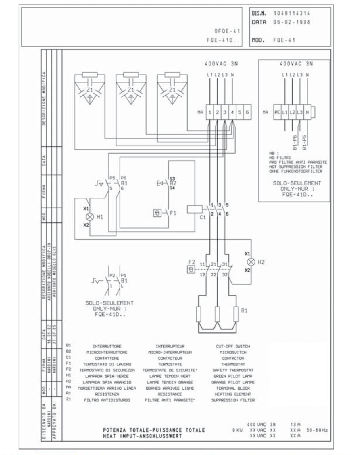
– The appliance must be installed in strict
compliance with the directions given in the
attached drawings.
– Appliances should only be installed on units
made of metal (and not wood and/or other
flammable materials).
– Take particular care with the power lead: the
channelways must be perfectly smooth with no
sharp corners and/or edges. The lead must not, at
any point, be subjected to temperatures of more
than 50°C above normal room temperature.
START-UP
Function check
– Start-uptheappliancefollowingtheinstructions
given; check function regularity and make sure
that the controls and heating elements are in
good working order, testing them with the
various function positions.
– The appliance is equipped with an internal
safety thermostat for each well, which cuts off
the power supply to the heating elements
whenever the main temperature regulator is
faulty.
– If necessary consult paragraph “Analysis of
several failures”.
Nominal heat input check
– After installation and at each maintenance
intervention check the heat input of the
appliance.
– The nominal heat input is stated in the
“Technical data” table.
– The appliance operates at the nominal heat
inputwhenthe electrical power istheone stated
in Table T1.
ATTENTION If the power supply value is not
within the limits indicated in Table T1, interrupt
the operation of the appliance and contact the
electricity delivery body.
ANALYSIS OF SEVERAL FAILURES
Heating elements do not heat up
– Check fuse valves
– Main switch off
– Insufficientpowerorwrongelectricalconnection
– Temperature regulation thermostat faulty
– Safety thermostat activated (because the main
temperature regulator is faulty). To reset the
safetythermostat, remove thescrew sealing the
thermostat access hole on the control panel.
Reset the thermostat, pressing with a pointed
tool (e.g. slender screwdriver).
Diffcult or lacking temperature adjustment
INSTALLATION INSTRUCTIONS
WARNINGS
Installation, adjustments and maintenance of the
appliances must be done by authorized installers,
in accordance with the safety standards in force.
Themanufacturerdeclines any responsibility
if such obligation is not observed.
INSTALLATION
Positioning
– The overall/connection dimensions and the
technical data are stated in the pages in the
appendix.
– Install the appliances only in sufficiently aired
rooms.
– Position appliances at least 10 cm from the
nearby walls. Such distance can be less when
the walls are incombustible or protected by a
thermal insulator.
– The appliances are not suitable for built-in
installation.
Assembly
– Remove the film which protects the external
panels. Any glue remaining on these is to be
removed with a suitable solvent.
In line union of the appliances
– Put the appliances next to eachother and level
them at the same height.
– Unite the appliances using the special union
joint-coverings supplied upon request.
Electrical connections
– The appliances are designed to operate at the
voltage indicated on the rating plate.
– Each appliance must be connected to an
independent mains supply of suitable capacity
(totalpower indicated in “Technicaldata”table)
viaan input terminal boardwithflexible rubber
cable, insulated at a level not below H07RN-F.
– Make sure that the cables lenght allows for the
live wires to disconnect from terminal block
before the yellow/green ground wire, in case of
simultaneous pull.
– Automaticcutoutomnipolarswitchesofsuitable
capacity (with contacts opening to at least 3
mm)andhighly sensitive automatic differential
protective devices must be fitted. These must
ensure that there is no direct or indirect contact
between live components and fault currents
and the ground, in accordance with current
regulations (maximum admissible leakage
current 1 mA/kW).
Earth and unipotential connections
– Appliances must be earthed on terminals
marked with the symbol .
– Connectthemetallicstructureofeveryelectrical

12/32 Electric heated fryers 600 series (30363)
– Temperature regulation thermostat faulty
– Wrong connection or heating elements faulty
(replace faulty element).
REPLACEMENT OF PARTS SUBJECT TO CHANGE
IMPORTANT Beforecarryingout repairs, unplug
appliance from mains disconnecting the main
switch.
Sealed components must not be tampered
with.
Temperatureregulationthermostatandmanually-
reset safety thermostat
– Drain oil from the relevant well, emptying it
completely (see paragraph headed “Oil
drainage”)
– Remove control panel.
– Loosen thermostat bulb to be changed; this is
secured between the heating elements with a
flexible clip.
– Disconnect electrical connections between
thermostat and other devices
– Change component.
Well heating elements
– Drain oil from the relevant well, emptying it
completely (see paragraph headed “Oil
drainage”)
– Remove control panel and cover protecting
harnessing on heating elements.
– Loosen thermostat bulbs which are secured
between the heating elements (to remove them,
loosen screws securing the supporting plates)
– Disconnect heating element.
– Change component.
USE AND MAINTENANCE
WARNINGS
Caution, appliance with hot surfaces!
The appliance is for professional use and must be
used by trained personnel. It is for the cooking of
food. Any other use of the appliance is considered
improper.
IMPORTANT:neverstartup appliance unless
the well contains oil.
The installation and adaptation to other voltages
(if possible) must be done by qualified and
authorized installers.
In case of breakdown diconnect the main switch.
Sealed components must not be tampered with.
For repairs consult only authorized service centres
and ask for original spare parts only.
Themanufacturerdeclinesanyresponsability
if such obligations are not observed.
Carefully read this booklet and keep it in a safe
place. Before using the appliance carefully clean
all the surfaces that will come in contact with food.
Furthermore..
Used oil must always be changed to prevent the
flame point from lowering and thereby creating a
fire risk; in this way, the boiling oil is also less
likely to spatter.
Do not fry pieces of food which are large or have not
been drained, as these may cause the oil to spit.
Do not use the well when the oil has dropped below
the minimum level indicated, as this may cause the
oil to catch fire.
Safety devices
Appliances are equipped with following:
– Additional safety thermostat, which
automatically cuts off the electricity supply to
heatingelementsand stops the heating function
when oil temperature exceeds the maximum
working temperature (operating thermostat
faulty).Ifthis should occur, cut offtheelectricity
supplytotheappliance and contact your nearest
customer service centre.
– Safety oil drainage tap against accidental
openings during work.
USE
Filling well
– Close the drain cock by turning the control lever
to setting .
– Pour the oil or fat blocks into the frying well and
fill up to the notch indicating the minimum level.
–IMPORTANT: Do not heat up the fryer
unless the well contains oil!
Operation
To switch on heating (pilot lamp on) turn the
temperatureregulatorknobonthedesiredworking
position.
0off
60 °Cminimum temperature
intermediate temperatures
180 °Cmaximum temperature
Switching off heating
– Turn temperature regulator knob on position
“0” (pilot lamp off).
Oil drainage
Important: The container used for well drainage
mustbelargeenough andofheatresistantmaterial.
– Insert the extension hose with the bayonet
safety joint (supplied with fryer unit) into the
drainage outlet on the well.
– Move the control lever on the drain cock to
setting (pressing the lever down and
pulling it forward).
CLEANING AND MAINTENANCE
– Before any cleaning operation disconnect the
electrical supply (if present).
– It is necessary to avoid rusty water being in
contact with stainless steel surfaces. Therefore

Electric heated fryers 600 series (30363) 13/32
before filling wells with water open water tap
and let water flow until it is perfectly clear.
– Clean stainless steel surfaces daily with water
and non abrasive common detergents, rinse
well and dry thoroughly.
– Do not use iron scouring pads or chlorate
products.
– Do not use sharp objects which can scratch and
ruin the steel surface.
– Do not use corrosive products to clean the floor
under the appliance.
– Do not wash the appliance with water jets.
– Before a long period of inactivity disconnect the
main switch. Proceed to its thorough cleaning.
– At least twice a year, ask for the intervention of
anauthorizedtechnicianauthorizedfor checking
the appliance. It is advisable in any case to
stipulate a maintenance contract.
LIST OF PARTS SUBJECT TO REPLACEMENT
– Heating elements
– Safety thermostats
– Temperature regulation thermostats
– Temperature regulation thermostat knobs
– Oil drainage cock
– Switch
– Contactor

Kokonaisteho - Totaleffekt - Total power
Behållarens volym max. - Max. capacity
Påfyllnadsmängd max. - Max. storage capacity
TEKNISET TIEDOT - TEKNISKA DATA - TECHNICAL DATA
Ø
MIN
MAX
mm
12 ÷18
12 ÷18
V
3NAC 400V
3NAC 400V
A
13
26
Altaan
tilavuus
MAX
l.
10
10 + 10
Täyttö-
määrä
MAX
kg
1,5
1,5 + 1,5
T1.1 (Mod. OFQE-41.../61...)
MOD.
OFQE-41
OFQE-61
kW
9
18
H 07
RN-F
5 x 1,5
5 x 4

OFQE-41, OFQE-61
ASENNUSKUVA - INSTALLATIONBILD - INSTALLATION DIAGRAM
(Mitat cm - Mått cm - Measurements cm)
MVerkkoliitin - Nätanslutning - El. power connection blocks
PSähkökaapelin vedonpoisto - Dragavlastare - Electric cable stress relief
5,3 60
5,92
11
42,5
6,5
5,11
5,51
M
P
5,2
6,64
3.56
40
94
M
P
6,9
4,1
8,4
PM
3.56
60
5,2
6,64
94
M
P
6,9
4,1
8,4
PM
06
06
1,4
60
3,6 3,6
6,9
8,4
40
3,6 3,6
6,9
8,4
OFQE-61
OFQE-41

KYTKIN
MIKROKYTKIN
KONTAKTORI
TERMOSTAATTI
TURVATERMOSTAATTI
VIHREÄ MERKKILAMPPU
ORANSI MERKKILAMPPU
VERKKOLIITIN
LÄMMITYSVASTUS
VERKKOSUODIN

KYTKIN
MIKROKYTKIN
KONTAKTORI
TERMOSTAATTI
TURVATERMOSTAATTI
VIHREÄ MERKKILAMPPU
ORANSI MERKKILAMPPU
VERKKOLIITIN
LÄMMITYSVASTUS
VERKKOSUODIN
This manual suits for next models
1
Table of contents
Other Metos Fryer manuals