14/45Gas ranges (PCG/CFG/CVG/CFGE/CCG)
indicated on the rating plate (variation of ±10%
is allowed).
– Each appliance must be connected to an
independent mains supply of suitable capacity
(totalpower indicated in“Technical data” table)
viaan input terminalboard with flexible rubber
cable, insulated at a level not below H07RN-F
and protected by a metal or rigid plastic tube.
– Automaticomnipolarcutoutswitchesofsuitable
capacity (with contacts opening to at least 3
mm)and highly sensitive automaticdifferential
protective devices must be fitted. These must
ensure that there is no direct or indirect contact
between live components and fault currents
and the ground, in accordance with current
regulations (max-imum admissible leakage
current 1 mA/kW).
Earth and unipotential connections
– Appliancesmustbe earthedonterminalsmarked
with the symbol .
– Connectthemetallicstructureofeveryelectrical
appliance installed to the terminals, marked by
the symbol , and located next to the earth
terminals (unipotential system).
CONVERSION TO ANOTHER TYPE OF GAS
To adapt appliances to work with other types of
gas carry out all the operations stated below.
Nozzles, minimum adjustment screws and
adhesive labels are in the bag supplied with the
appliance.
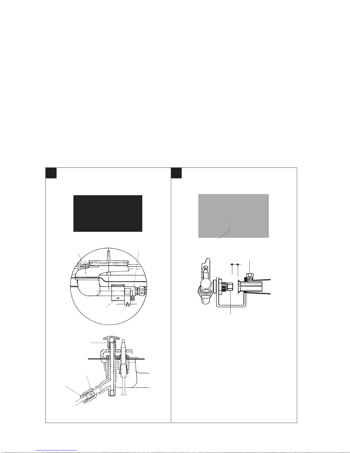
Replacement of nozzle and burner primary air
adjustment (Fig. 1 - 2)
– Remove cooking hob control panel
– Remove the oven floor
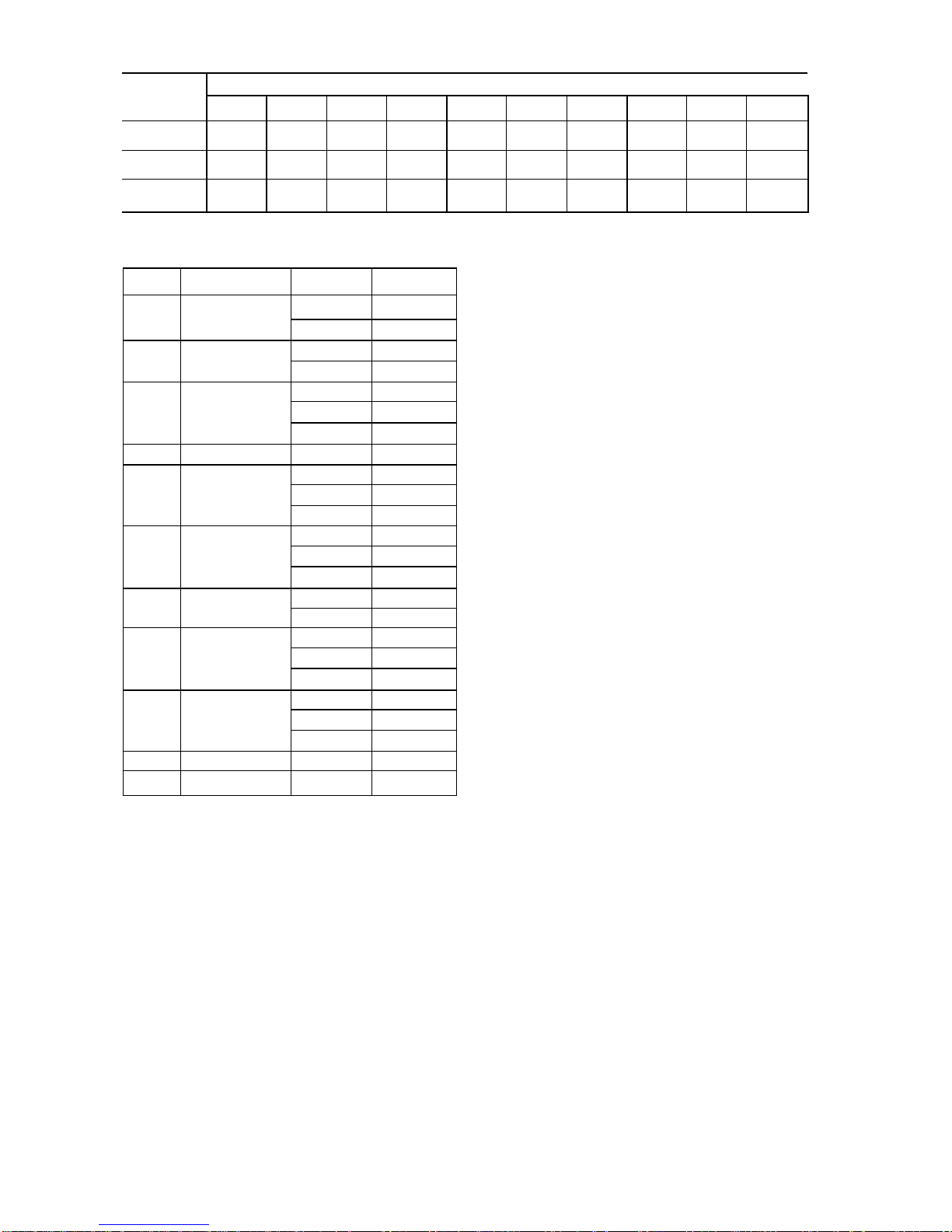
– Unscrew nozzle U and change it with the proper
one according to Table T1.
– LoosefixingscrewVand operating on the shutter
adjust primary air inlet at the distance “A”
indicated on Table T1.
– Screw down fixing screw V and seal it with red
paint.
Replacement of gas cock minimum adjustment
screw (Fig. 1 - 2)
– Remove cooking hob control panel
– Unscrew the minimum screw VM and replace it
with the proper one indicated in table T1.
Replacement of pilot burner nozzle (Fig. 1 - 2)
– Remove cooking hob control panel
– Unscrew pipe fitting R and replace nozzle UP
with the proper one indicated in Table T1.
– Screw down pipe fitting R.
Replacement of gas preset adhesive label
– Applythe correct adhesive labelwhich indicates
the new type of gas for which the appliance is
now set.
INSTALLATION INSTRUCTIONS
WARNINGS
Installation, adjustments and maintenance of the
appliances must be done by authorized installers,
in accordance with the safety standards in force.
The manufacturer declines any responsibility
if such obligation is not observed.
NOTE
Combination ranges (with electric heated oven)
are in accordance with the EEC Directive 89/336
on the radio interference suppression.
Soundlevelduring operationsdoesnotexceed70 dB.
INSTALLATION
Positioning
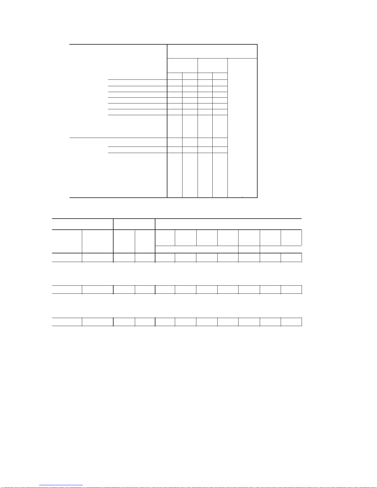
– The overall/connection dimensions and the
technical data are stated in the pages in the
appendix.
– Install the appliances only in sufficiently aired
rooms.
– Cooking ranges are type “A” appliances and for
this reason the rooms must be ventilated in
accordancewiththetechnicalstandardsinforce.
– Position appliances at least 10 cm from the
nearby walls. Such distance can be less when
the walls are incombustible or protected by a
thermal insulator.
– The appliances are not suitable for built-in
installation.
Assembly
– Remove the film which protects the external
panels. Any glue remaining on these is to be
removed with a suitable solvent.
– Level appliance by means of the adjustable feet.
– Assemble the stack extension (if foreseen) by
following the instructions enclosed with the
extension itself.
In line union of the appliances
– Put the appliances next to eachother and level
them at the same height.
– Unite the appliances using the special union
joint-coverings supplied upon request.
Connection to the gas piping
– Before carrying out the connection consult the
gas delivery body.
– Install a fast-closing cut-off cock upstream from
the appliance in an easily accessible place.
– Check for any leaks in the connection points.
– Check if the appliance is set for the type of gas
with which it will be fed. If it is not, read
paragraph “Adaptation to another type of gas”.
Electrical connections (combination ranges)
– The ovens are designed to operate at the voltage