SGM LEKTRA FLOWMETER Guide

FLOWMETER
ultrasonic flow transmitter
technical documentation EN Rev. F

Page 2 of 36
FLOWMETER - contents
CONTENTS
pag. 3
pag. 4
pag. 5
pag. 6
pag. 7
pag. 9
pag. 11
pag. 14
pag. 36
1-WARRANTY
2-PRODUCT
3-PERFORMANCE SPECIFICATIONS
4-DIMENSIONS
5-INSTALLATION
6-ELECTRICAL CONNECTIONS
7-LOCAL OPERATOR INTERFACE (LOI)-VL601
8-SETUP
10-FACTORY TEST AND QUALITY CERTIFICATE

Page 3 of 36
FLOWMETER - warranty
Products supplied by SGM LEKTRA are guaranteed for a period of 12 (twelve) months from delivery date accord-
ing to the conditions specified in our sale conditions document.
SGM LEKTRA can choose to repair or replace the Product.
If the Product is repaired it will maintain the original term of guarantee, whereas if the Product is replaced it will
have 12 (twelve) months of guarantee.
The warranty will be null if the Client modifies, repair or uses the Products for other purposes than the normal
conditions foreseen by instructions or Contract.
In no circumstances shall SGM LEKTRA be liable for direct, indirect or consequential or other loss or damage
whether caused by negligence on the part of the company or its employees or otherwise howsoever arising out
of defective goods
1-WARRANTY
Page 4 of 36
FLOWMETER0F4DS
24Vdc 20÷30Vdc
FR0111600193
2
3
1Mod.
P.S.
S.N.
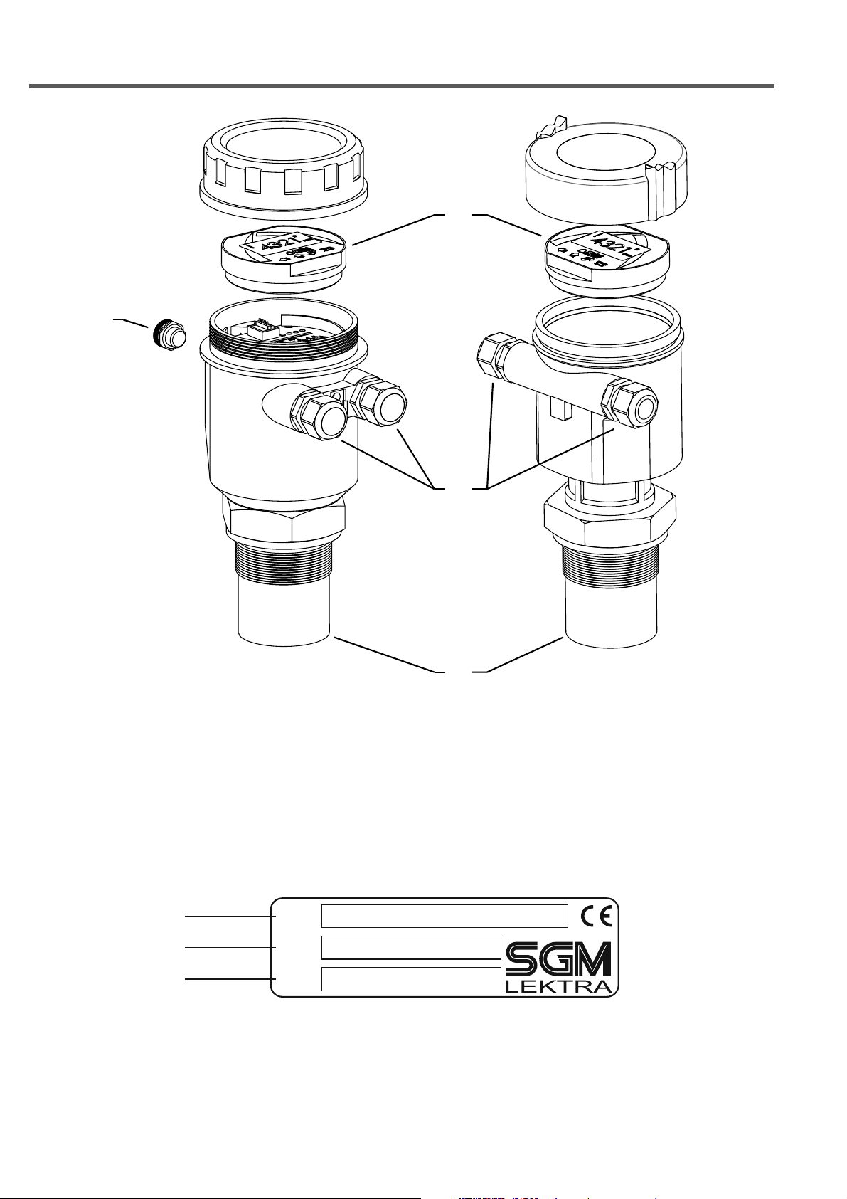
FLOWMETER - features
2- PRODUCT
1. Anticondensation filter
2. M20 skintop
3. VL601 (opt.)
4. Sensor
2.1 IDENTIFICATION
Each meter has an adhesive identification plate on which are the meter main data. The following picture describes the
information and data on the identification plate.
1
2
3
4
1. Product code 3. Serial number2. Power supply

Page 5 of 36
3-FEATURES
FLOWMETER - features
Housing/sensor material
PC or Al / PP or PVDF wetted part
Mechanical installation
2” GAS M (PP flange DN80 opt.)
Protection degree
IP67/IP68 (Sensor)
Electrical connection
Internal push connectors
Working temperature
-20 ÷ +60°C
Pressure
from 0,5 to 1,5 bar (absolute)
Power supply
12Vdc / 24Vdc
Power consumption
1,5W (4-wires)
Analog output
4...20mA, max 750ohm
Relays output
n°2 3A 230Vac (n.o.)
Digital communication
MUDBUS RTU
Max measure range
max 0.25 ÷ 5m
In case of non perfectly reflecting surfaces, the maximum distance value will be reduced
Blind distance
0,25m
Temperature compensation
digital from -30 to 80°C
Accuracy
±0,2% (of the measured distance) not better than ±3mm.
Resolution
1mm.
Calibration
4 buttons or via MODBUS RTU
Warm-up
1 minutes typical
LCD Display
Plug-in display/keyboard 4 buttons matrix LCD

Page 6 of 36
4-DIMENSIONS
FLOWMETER - dimensions
4.1 MECHANICAL DIMENSIONS

Page 7 of 36
5.1 MOUNTING PRECAUTIONS
5.1.1 Mounting position
- Use a protective cover to protect the sensor from weather and direct sunlight (b).
- Do not install the sensor near the load zone (a).
- Make sure that in the sensor emission beam (lobe “ ”) there are no obstacles (c) that can be intercepted as level.
- Make sure that there is not foam presence on the product surface to be measured.
Lobo “α“
FLOWMETER 5mt 10°
Make sure that the FLOWMETER distance from the weir channel point is equal or greater than to the minimum
allowed distance. In the following figure, the example with a Venturi channel (min. dist.4xb0) and a
Palmer-Bowlus channel (min. dist. D/2) prefabricated (available in our catalog)..
Venturi channel Palmer Bowlus
FLOWMETER - installation
5-INSTALLATION

Page 8 of 36
FLOWMETER - installation
5.1.2 Blind distance
During installation is important to remember that in the sensor vicinity there is a blind zone (or BLIND DISTANCE)
of 0.25m where the sensor can not measure.
Blind Distance
0.25mt (5mt)

Page 9 of 36
No
c
No
c
-
+
A
B
RL1
RL2
4÷20mA
MUDBUS
12Vdc / 24Vdc
FLOWMETER - electrical connections
6-ELECTRICAL CONNECTIONS
6.1 WIRING
1) Separate the engine control cables or power cables from the FLOWMETER connection cables
2) Open the cap by unscrewing.
3) Lead the cables into the transmitter through the glands
4) Do not use sleeves terminals, because they might interfere with the VL601 module insertion
5) Close the cap and tighten the cable glands
6.2 HUMIDITY INFILTRATIONS
To avoid the humidity infiltration inside the housing is recommended:
- for electrical connections, use a cable with a 6÷12mm outer diameter and fully tighten the M20 cable gland
- fully tighten the cap
- position the cable so that it forms a downward curve at the M20 output; in this way the condensation and/or rain
water will tend to drip from the curve bottom

Page 10 of 36
1
2
3
USB/RS485
FLOWMETER - electrical connections
6.3 DIGITAL COMMUNICATIONS CONNECTION
7.3.1 MODBUS RTU PC connection
1) FLOWMETER with MODBUS RTU communication protocol
2) USB/RS485 interface module, cod.694A004A
3) MODBUS RTU communication S/W, cod.010F119A, for FLOWMETER transmitter
With this software is possible:
- connect, by selecting the UID address, the FLOWMETER transmitters in MODBUS RTU network
- read on your PC monitor all measures in reading and FLOWMETER operation data
- programming all FLOWMETER configuration parameters
- storing on files, data logger function; FLOWMETER measures in reading and operating states
Other manuals for FLOWMETER
1
Other SGM LEKTRA Transmitter manuals

SGM LEKTRA
SGM LEKTRA RPL81 User manual

SGM LEKTRA
SGM LEKTRA PTU50 User manual

SGM LEKTRA
SGM LEKTRA PTU15 User manual

SGM LEKTRA
SGM LEKTRA RPL81 User manual

SGM LEKTRA
SGM LEKTRA KPT Guide

SGM LEKTRA
SGM LEKTRA METER Series Quick start guide

SGM LEKTRA
SGM LEKTRA RPL75 User manual

SGM LEKTRA
SGM LEKTRA TC26 User manual

SGM LEKTRA
SGM LEKTRA RPL75 User manual

SGM LEKTRA
SGM LEKTRA PTU51 User manual


Popular Transmitter manuals by other brands


Dejero
Dejero EnGo 3x manual

Rosemount
Rosemount 4600 Reference manual

Speaka Professional
Speaka Professional 2342740 operating instructions

trubomat
trubomat GAB 1000 instruction manual

Teledyne Analytical Instruments
Teledyne Analytical Instruments LXT-380 instructions

Rondish
Rondish UT-11 quick start guide


