Metrodata FM4800 User manual
Metrodata Ltd
Fortune House
Crabtree Office Village
Eversley Way
Egham
Surrey TW20 8RY
United Kingdom
tel: +44 (0) 1784 744700
fax:+44 (0) 1784 744730
website: www.metrodata.co.uk
Metrodata FM4800 User Manual
www.metrodata.co.uk
FM4800
User
Manual


Metrodata Ltd
No part of this publication may be reproduced, transmitted, transcribed, stored in a retrieval
system, or translated into any language or computer language, in any form or by any means,
electronic, mechanical, magnetic, optical, chemical, manual or otherwise, without the prior
written permission of
Disclaimer
Metrodata Ltd makes no representations or warranties with respect to the contents hereof
and specifically disclaims any implied warranties or merchantability or fitness for any
particular purpose. Further, Metrodata Ltd reserves the right to revise this publication and to
make changes from time to time in the content hereof without obligation of Metrodata Ltd to
notify any person of such revision or changes.
Trademarks
The Trademarks of other Corporations which may be used in this manual are hereby
acknowledged.
Copyright © 2006 by Metrodata Ltd
All Rights Reserved
Metrodata Ltd,
Fortune House,
Crabtree Office Village,
Eversley Way,
Egham, Surrey, TW20 8RY,
United Kingdom.
Tel: +44 (0) 1784 744700
Fax: +44 (0) 1784 744730
e-mail: [email protected]
www: http://www.metrodata.co.uk
ftp://ftp.metrodata.co.uk


CONTENTS
1 INTRODUCTION 1
1. 1 About The FM4800 1
1. 2 Typical FM4800 Installation 2
1. 3 About This Manual 3
1. 4 Conventions 4
2 STATUTORY INFORMATION 5
2.1 Performance 5
2.2 Safety 5
2.3 Electromagnetic Compatibility 5
2. 4 EN55022 Declaration 5
2. 5 FCC Declaration 5
2.6 Power Supply 6
2.7 On board batteries 6
3 TECHNICAL OVERVIEW 7
3. 1 G.703 Signal Transmission 7
3. 2 Payload 7
4 INTRODUCING THE FM4800 9
4. 1 Front panel 9
4. 2 Rear panel 10
4. 3 Power Supply 10
4. 4 Remote Management port 11
4. 5 Alarm Extension 11
4. 6 Terminal Port 12
4 . 6. 1 Minimum RS232 connection 13
4 . 6. 2 V.24 Terminal Cable 25 Way to 25 Way 13
4 . 6. 3 Connecting to a PC COM port 14
4. 7 X.21 DTE port 15
4. 8 X.21 to EIA-530 Conversion 16
4. 9 X.21 to RS-449 Conversion cable 17
4. 10 Network Connection 18
5 FM4800 INSTALLING & SETTING-UP 19
5. 1 Connections 19
5. 2 Power-Up Sequence 20
5. 3 User Interface 21
5 . 3. 1 TTY terminal 21
5 . 3. 2 VT100/VT220 and ANSI terminals 22
5. 4 Default settings 23
6 CONFIGURING THE FM4800 25
6. 1 Menu Structure 25
6. 2 Main Set-up Menu 26
6 . 2. 1 Alarm extension 26
6 . 2. 2 Clear Alarm Outputs 27
6. 3 General Set-up Menu 28
6 . 3. 1 Time 28
6 . 3. 2 Date 28
6 . 3. 3 Node name 28
6 . 3. 4 Password 29
6 . 3. 5 Telnet Timeout 29

6. 4 WAN (Line) Port Set-up Menu 30
6 . 4. 1 Framing 30
6 . 4. 2 Line coding 30
6 . 4. 3 Timing 30
6 . 4. 4 AIS Detection 31
6. 5 DTE Set-up Menu 32
6 . 5. 1 State 32
6 . 5. 2 Interface type 32
6 . 5. 3 Transmit timing 32
6 . 5. 4 Clock invert 32
6 . 5. 5 I Control 32
6 . 5. 6 C Current state 32
6. 6 V.24 Set-up Menu 33
6 . 6. 1 Terminal type 33
6 . 6. 2 Baud rate 33
6 . 6. 3 Parity 33
6 . 6. 4 Data bits 33
6 . 6. 5 Stop bits 33
6 . 6. 6 Modem support 33
6 . 6. 7 Load new config 34
6. 7 Testing 34
6. 8 Special 35
6 . 8. 1 Software version 35
6 . 8. 2 Hardware version 35
6 . 8. 3 Warm start 35
6 . 8. 4 Cold start (Caution!) 35
6 . 8. 5 Event Logs 36
6. 9 Performance Data 37
6. 10 Unit Set-up Checklist 38
7 ANALYSING PERFORMANCE 39
7. 1 Introduction 39
7. 2 Errors and Alarms 39
7 . 2. 1 Error types 39
7 . 2. 2 DTE Port alarm responses 39
7 . 2. 3 WAN (Line) Port alarm responses 40
7 . 2. 4 Summary of Errors and Alarms by mode 40
7 . 2. 5 Error and Alarm definitions 41
7. 3 Performance menu 42
7 . 3. 1 Interface 42
7 . 3. 2 Display mode 42
7. 4 Physical layer statistics – Reports 43
7 . 4. 1 Full Report 43
7 . 4. 2 Rolling report 44
7. 5 Physical layer statistics - Summaries 45
7 . 5. 1 Screen presentation 45
7 . 5. 2 Presentation display modes 45
7 . 5. 3 Summary style 46
7 . 5. 4 Summary display - COUNTS style 47
7 . 5. 5 Summary display - G.821 style 48
7 . 5. 6 Summary display - Percent G.821 style 49

8 REMOTE MANAGEMENT 51
9 TEST & TROUBLESHOOTING 53
9.1 Testing Menu 53
9 . 1. 1 DTE 53
9 . 1. 2 NI 53
9 . 1. 3 Test pattern 53
9.2 DTE interface 54
9 . 2. 1 DTE Loop 54
9.3 Network Interface (NI) 55
9 . 3. 1 NI Remote Loop 55
9 . 3. 2 NI Local Loop 56
9.4 Test Pattern 56
9.5 Remote management during testing 56
9.6 Troubleshooting 57
10 FM4800 SPECIFICATIONS 59
10. 1 FM4800 Default Settings 60
10. 2 Glossary 61


INTRODUCTION
1 76-02-007F
1 INTRODUCTION
1. 1 About The FM4800
The FM4800 Data Service Unit (DSU) is used to connect high performance bridges and
routers to high speed 8Mbit/s services.
The FM4800 interfaces a E2 service (8.448 Mbit/s) and Data Terminal Equipment presenting
an X.21 interface.
FM4800 DSU’s are used in pairs, one at either end of a Wide Area Network (WAN) link. One
end is called the LOCAL node, and the other the REMOTE node.
The FM4800 also provides extensive performance monitoring facilities. It can monitor
degraded line performance and has extended alarm processing on the connection, giving
the network manager extensive visibility and control of the wide-area link.
A record of all error conditions, including major and minor alarms and bit errors, is kept for
the last 24 hours. Statistics are recorded every 15 minutes and processed into G.821 format.
Ninety-six 15 minute periods are kept, which means that 24-hour coverage is maintained on
a rolling basis.
Diagnostics are provided to localise a fault condition on the line. These are provided by
various types of loopback.
The FM4800 may be managed by connecting a video terminal to the unit, either directly
through a serial interface, or via a multiplexer or modem. With the optional LM1100 SNMP
Enabler the FM4800 can be managed remotely with a Simple Network Management
Protocol (SNMP) management system connected to the LAN. Telnet access can also be
achieved through the LM1100.
Finally, with a video terminal connected to the serial interface port, the FM4800 doubles as
a terminal adapter and connection may be made to remote Telnet-accessible devices via the
LM1100 SNMP Enabler.
INTRODUCTION
76-02-007F 2
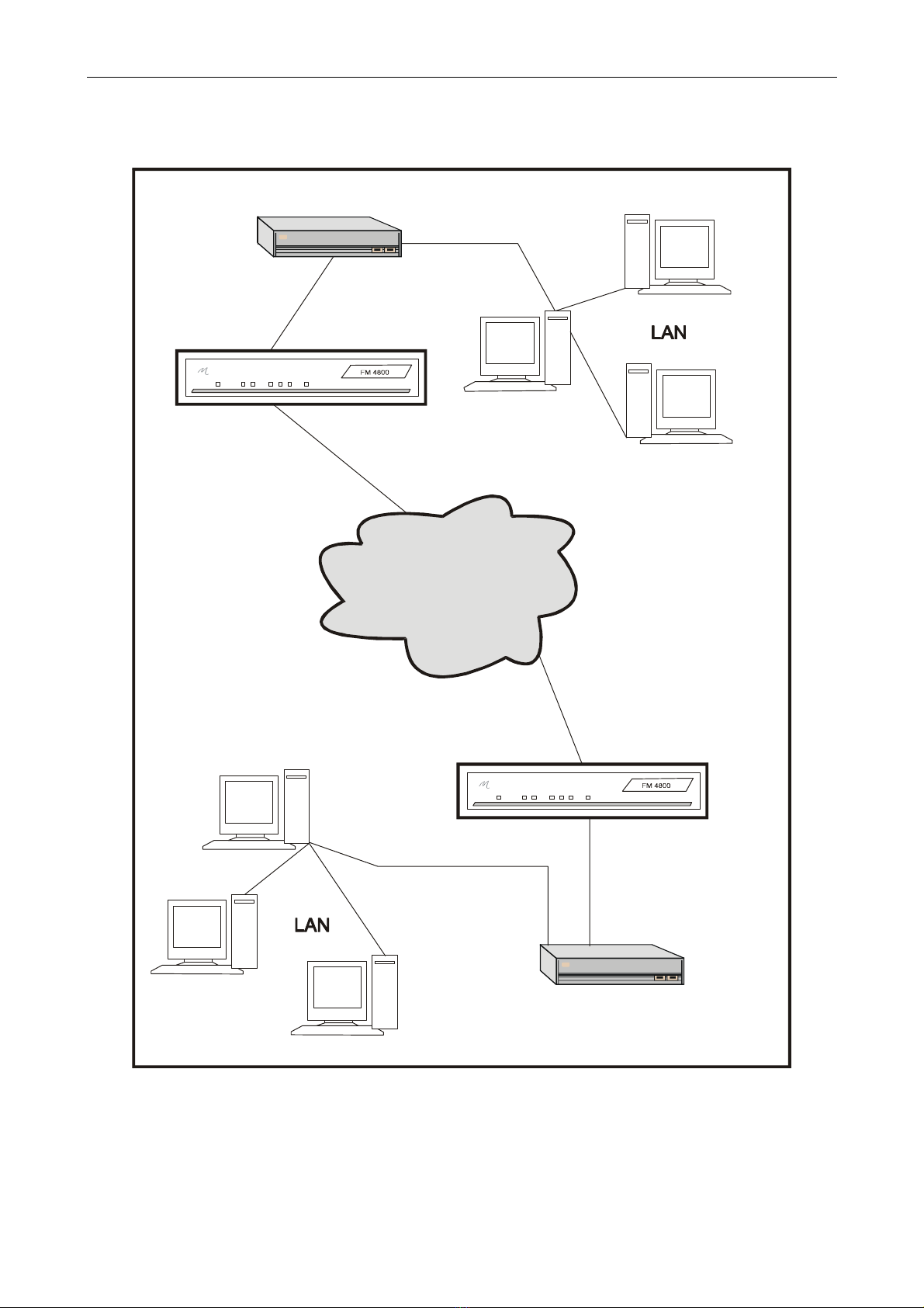
1. 2 Typical FM4800 Installation
Figure 1. 1 FM4800 Deployment
E2 LINK
E2 LINK
FM4800
FM4800
WAN
ROUTER
ROUTER
X.21
X.21

INTRODUCTION
3 76-02-007F
1. 3 About This Manual
This user manual describes the installation, commissioning and operation of the Metrodata
FM4800 Data Service Unit. It describes the operational functions of the unit, as well as the
extensive performance monitoring facilities. A glossary is provided at the rear which explains
the abbreviations introduced by this manual.
It is important that you read and understand the performance and operating limitations in
Section 2 and specifications in Section 10 of the FM4800 before attempting any connections.
Section 3, Technical Overview describes the G.703 standard which is applicable to the
operation of the FM4800.
Section 4, Introducing FM4800, describes the front and rear panels of the FM4800 with
details of connectors, connector layouts and alarm lights. It is worthwhile to study the detail
of Sections 3 and 4 since this helps in installing and testing the unit.
Section 5, Installing & Setting-up, takes you through the basic steps of connecting the
FM4800 to the external devices that you may have.
The structure of the menus is described in Section 6, Configuring the FM4800, as well as
each of the options on every menu. Part of this Section describes a typical commissioning
procedure, and acts as a checklist for both first-time and experienced users of the FM4800.
Section 7, Analysing Performance, shows you how to monitor the E2 link and change the
summary report options for the FM4800.
Section 8 introduces the concept of remote management of the FM4800 using Simple
Network Management Protocol with an LM1100 SNMP Enabler. However, this subject is too
detailed to be described in this manual, and you should refer to the LM1100 SNMP Enabler
User manual.
The extensive diagnostic testing and troubleshooting functions of the FM4800 are described
in Section 9, including testing both local and remote connections. The troubleshooting
subsection is provided to assist with isolating any errors or faults that may occur.
Section 10 lists the various specifications of the FM4800, and at the rear of the manual menu
charts are included as an aid to installing the FM4800.

INTRODUCTION
76-02-007F 4
1. 4 Conventions
Notes are used to provide the reader with either statutory information which must be
observed for safety reasons, or additional information which may increase the FM4800's
effectiveness.
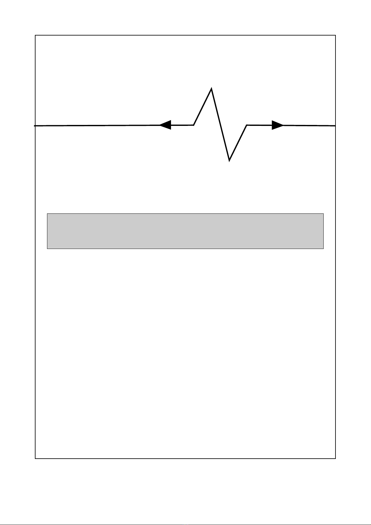
A pair of arrows around a word indicates a key on the keyboard, such as
<space> or <escape>
There are two exceptions to this, which appear on some of the menus:
<display> indicates that selecting the option will lead to data being displayed on the screen.
<menu> indicates that the option leads to another menu, from which further options may be
chosen.
Screen displays that contain variable information, such as the current date or time, show the
variable in italics, surrounded by square brackets, i.e. [time], or “[nodename]”. The
speechmarks indicate that the field contents can be specified by the user.
Where menu items are referred to in the text, these are shown in italics to help the reader to
cross relate to menu information.
Screen examples: the FM4800 allows you to use one of three options for displaying the
menus on a terminal - ANSI, VT100/VT220 or TTY.
The screen examples in this manual use VT100/VT220 and are shaded to allow easy
identification by the reader.

STATUTORY INFORMATION
5 76-02-007F
2 STATUTORY INFORMATION
2.1 Performance
The FM4800 complies with the requirements of G.703 at 8.448 Mbit/s, BS6328 Section 8.2
Clause 5.2. It has a port defined as 5C (Unstructured operation) in the context of Oftel
OTR.001.
These standards permit connection to the public 8.448 Mbit/s network network.
The FM4800 maintains bit integrity between the network port and the DTE port.
The FM4800 should not be connected to cabling which would be required by BS6701 to be
equipped with over-voltage protection.
The worst case delay through the FM4800 is 16 microseconds, and the worst case round
trip delay is 64 microseconds.
2.2 Safety
The following ports are designated SELV (Safety Extra Low Voltage) within the scope of
EN41003:
X.21port (DTE port)
Terminal port
Management port
Alarm extension port
E2 Line Port (WAN port)
These ports should only be connected to SELV ports on other equipment in accordance with
EN60950 clause 2.3.
2.3 Electromagnetic Compatibility
In order to ensure EMC compliance all signal and data cables and connectors must use a
screened connector shell with a screened cable. The cable screen must be terminated to the
screened connector shell and not connected to any pins of the connector. Failure to use the
correct connector may compromise EMC compliance.
2. 4 EN55022 Declaration
The FM4800 is a Class A product. In a domestic environment it may cause radio interference
in which case the user may be required to take adequate measures.
2. 5 FCC Declaration
This equipment has been tested and found to comply with the limits for a Class A digital
device, pursuant to Part 15 of the FCC Rules. These limits are designed to provide
reasonable protection against harmful interference when the equipment is operated in a
commercial environment. This equipment generates, uses, and can radiate radio frequency
energy and, if not installed and used in accordance with the instruction manual, may cause
harmful interference to radio communications. Operation of this equipment in a residential
area is likely to cause harmful interference in which case the user will be required to correct
the interference at its own expense.

STATUTORY INFORMATION
76-02-007F 6
2.6 Power Supply
The FM4800 is powered by a mains power supply with an input voltage range 100-250 VAC/
50-400 Hz. The maximum input current is approximately 0.2A rms. at 240V.
An alternative -48V DC power supply unit is available, the supply definition being minus 36
to minus 72VDC. The maximum input current is 1.0A. The -48V DC power supply provides
cable ends for connection by the user to the main power source. The cable colour codes are:
Figure 2.1 Connection of -48VDC outlet
Safety Notes:
Excessive voltages are present inside the unit. There are no user serviceable parts inside
the unit, and the cover should not be removed by unqualified personnel. The unit must not
be exposed to damp or condensing conditions. The FM4800 must be connected to safety
earth for correct operation.
2.7 On board batteries
The user is reminded that Metrodata motherboards use Lithium/Thionyl Chloride 3.6 volt
battery cells for the maintenance of RAM.
These batteries must be handled with care. There may be a risk of explosion if a battery is
incorrectly replaced. Do not recharge, force open, heat or dispose of by fire. Replace only
with the same type of battery. Disposal must be in accordance with the manufacturer’s
instructions. If in doubt about any aspect of battery replacement or disposal, please call
Metrodata Technical Support Department.
Green/yellow Earth
Blue 48V DC
Black Zero

TECHNICAL OVERVIEW
7 76-02-007F
3 TECHNICAL OVERVIEW
The FM4800 is used on unframed G.703 digital services and a technical overviews of G.703
is provided.
3. 1 G.703 Signal Transmission
The signal is transmitted on 75 Ohm RG59 unbalanced coax. The signal has alternate mark
inversion (AMI) characteristics in accordance with G.703. A mark is transmitted as a 0⋅5 unit
interval (UI) wide pulse of amplitude 2⋅37V. Alternate marks have opposing polarity so that
'111' is transmitted as a positive pulse, a negative one and then another positive one. The
pulses have a duration of 50% so that strings of '1s' can be identified as a series of pulses.
This is because clocking information is derived from the transmitted signal. In addition,
strings of zeros are replaced with high-density binary 3 (HDB3) code words to ensure pulse
density (and therefore clocking information) and an average DC potential of 0V. The
transmission rate is 8⋅448 Mbit/s.
3. 2 Payload
The DTE connected to the FM4800 will be clocked at a line rate of 8⋅448 Mbit/s. Data from
the DTE is carried on the E2 aggregate as unstructured payload.

TECHNICAL OVERVIEW
76-02-007F 8
INTRODUCING THE FM4800
9 76-02-007F
4 INTRODUCING THE FM4800
The FM4800 is supplied in a metal enclosure for tabletop or 19” rack mounting using the
optional rack mounting ears that bolt onto the side of the module.
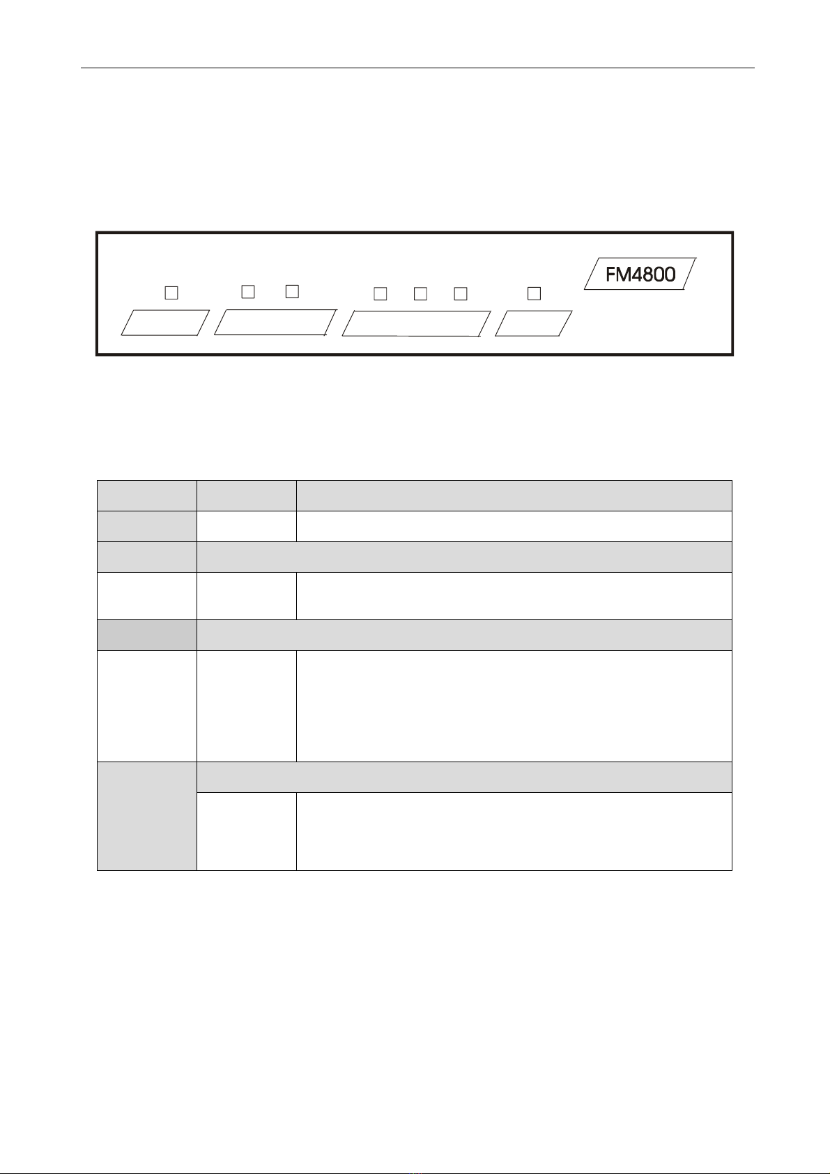
4. 1 Front panel
Figure 4.1 FM4800 Front panel
The FM4800 provides you with essential information through a series of LEDs on the front
panel. The colour of some of these LEDs will depend on the type of data that is being
handled at the time, and these are described in Figure 4.2 below.
Figure 4.2 FM4800 Front panel alarms
LED Colour Meaning
Power Red Mains power is being received.
Line
Major
Minor
Red
Yellow
LOS alarm is present
AIS or PSYN alarm is present.
DTE
Fault Red The TT clock is out of specification or the FM4800 has a
hardware timing fault.
TX Data
and
RX Data
Red
Green
Orange
Data being transmitted or received = 1
Data being transmitted or received = 0
The data is switching rapidly between 0 and 1.
Test
Red The E2 port is looped locally or remotely; or the remote
loop pattern has been sent.
Green The DTE port is looped
POWER TEST
LINE
MAJOR
LINE
MINOR
DTE TX
DATA
DTE RX
DATA FAULT
INTRODUCING THE FM4800
76-02-007F 10
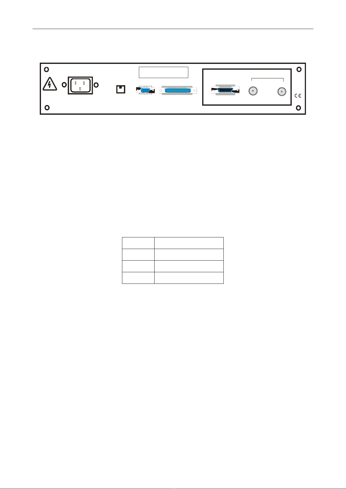
4. 2 Rear panel
Figure 4.3 FM4800 Rear panel
4. 3 Power Supply
The FM4800 is powered by a mains power supply with an input voltage range 100-250 VAC
/ 50-400 Hz. The maximum input current is 0⋅2A rms. at 240V.
An alternative -48VDC powered unit is available. The input voltage and current ranges are -
minus 36 to minus 72 volts DC. A Buccaneer type socket is fitted to the rear panel, and a
plug is provided with the unit for the customer’s own wiring. The connections are labelled on
the rear panel of the unit.
On some units, an additional Ground stud may be located on the rear panel to permit a
separate Ground connection to be made.
Figure 4. 4 -48VDC connections
Note: The FM4800 must be connected to safety earth for correct operation.
Pin no Connection
1-48VDC
2 Ground
30VDC
ALARM EXT. TERMINAL
Metrodata Ltd
MANAGED PDH DSU DTE PORT LINE
RX TX
HAZARD WARNING!
DO NOT OPEN WITH
POWER CONNECTED
MAN.
PORT
100-250VAC/50-400Hz

INTRODUCING THE FM4800
11 76-02-007F
4. 4 Remote Management port
If you have chosen the LM1100 SNMP Enabler option this port will contain an RJ45
connector, otherwise it will contain a blanking plug.
This port is labelled MAN PORT on the rear panel. The LM1100 SNMP Enabler option gives
access to the SNMP network management system via an IEEE 802.3/10BaseT interface on
the rear of the DSU.
Note: The Management port is regarded as a SELV port within the scope of EN 41003.
The layout of this port’s RJ45 connector is shown below:
Figure 4.5 Management port layout
4. 5 Alarm Extension
This port contains either a 6-pin mini-DIN connector or a 9-pin D-type connector, allowing
you to connect the major and minor alarm relay contacts within the FM4800 to a remote
indicator, such as a bell or a lamp. The two types of connectors are described below. The
Major alarm contacts are normally open, so that major alarm indication is given if the mains
power supply to the DSU should fail. The Alarm Relay port is regarded as a SELV port within
the scope of EN41003.
Figure 4.6 6-pin connector layout
Pin Signal
1Tx Data + ve
2Tx Data - ve
3Rx Data + ve
4Not connected
5Not connected
6Rx Data - ve
7Not connected
8Not connected
Pin Function
1Major common
2Minor N/C
3Major N/O
4Minor N/O
5Major N/C
6Minor common

INTRODUCING THE FM4800
76-02-007F 12
Figure 4.7 9-pin D-type connector layout
4. 6 Terminal Port
The terminal port is provided for local management of the FM4000. It is a female 25-pin D-
type connector with a full RS232 layout which is shown below.
Note: The Terminal port is regarded as a SELV port within the scope of EN 41003.
Figure 4.8 Terminal port connector layout
If the MODEM SUPPORT item in the V.24 SET-UP menu is set to its default value ON, then
RTS (pin 4 on the DSU terminal port) needs to be correctly driven, otherwise the user will be
permanently logged out of the DSU. To drive the RTS correctly, a fully configured cable can
be used together with a terminal that supports hardware handshaking. An alternative
approach is to connect the RTS and DSR signals together (pins 4 and 6) at the DSU end of
the cable. Obviously, the loop-backs will not be implemented if the management terminal is
remote, and connected via a modem.
Pin Function
1Shield
2Major common
3Minor N/O
4Minor N/C
5Not connected
6Major N/C
7Major N/O
8Minor common
9Not connected
Pin Function
1DCD
2Transmit
3Receive
4RTS
5CTS
6DSR
7Ground
8DCD
9-25 Not Connected
Table of contents
Other Metrodata Network Hardware manuals


Popular Network Hardware manuals by other brands


Rockwell Automation
Rockwell Automation Allen-Bradley ControlLogix EtherNet/IP user manual

eks
eks DL-485PBR manual

24online
24online SMS 100iX quick start guide

ADC
ADC HiGain HDSL2 manual

Digi
Digi Connect ES 4 SB quick start guide

Positron
Positron Teleline Isolator 751126/1 General description and installation guide