Metrodata ATM CBR DSU User manual
Metrodata Ltd
Fortune House
Crabtree Office Village
Eversley Way
Egham
Surrey TW20 8RY
United Kingdom
tel: +44 (0) 1784 744700
fax:+44 (0) 1784 744730
website: www.metrodata.co.uk
Metrodata ATM CBR (Circuit Emulation)
DSU User Manual
User
Manual
ATM CBR DSU


Metrodata Ltd
No part of this publication may be reproduced, transmitted, transcribed, stored in a retrieval
system, or translated into any language or computer language, in any form or by any means,
electronic, mechanical, magnetic, optical, chemical, manual or otherwise, without the prior
written permission of
Disclaimer
Metrodata Ltd makes no representations or warranties with respect to the contents hereof
and specifically disclaims any implied warranties or merchantability or fitness for any
particular purpose. Further, Metrodata Ltd reserves the right to revise this publication and to
make changes from time to time in the content hereof without obligation of Metrodata Ltd to
notify any person of such revision or changes.
Trademarks
The Trademarks of other Corporations which may be used in this manual are hereby
acknowledged.
Copyright © 2006 by Metrodata Ltd
All Rights Reserved
Metrodata Ltd,
Blenheim House,
Crabtree Office Village,
Eversley Way,
Egham, Surrey, TW20 8RY,
United Kingdom.
Tel: +44 (0) 1784 744700
Fax: +44 (0) 1784 744730
e-mail: [email protected]
www: http://www.metrodata.co.uk
ftp://ftp.metrodata.co.uk


CONTENTS
1 INTRODUCTION 1
1. 1 About the ATM CBR DSU Family 1
1. 2 ATM CBR DSU Typical Installation 3
1. 3 About this manual 4
1. 4 Conventions 5
2 STATUTORY INFORMATION 7
2. 1 Safety 7
2.2 Electromagnetic Compatibility 7
2. 3 EN55022 Declaration 7
2. 4 FCC Declaration 7
2. 5 Power Supply 8
2. 6 On-board batteries 8
2. 7 Laser Technology 9
3 INTRODUCING THE ATM CBR DSU 11
3. 1 Front panel 11
3. 2 ATM UNI and CBR LINE Network port identities 11
3. 3 Rear panels 12
3. 4 Power Supply 12
3. 5 Remote Management Port 13
3. 6 Alarm Extension 13
3. 7 Terminal port 14
3 . 7. 1 V.24 Terminal cable 25 way to 25 way 15
3 . 7. 2 Minimum RS232 connection 15
3 . 7. 3 Connecting to a PC COM port 16
3. 8 ATM UNI Port (Fibre) 17
3. 9 ATM UNI Port (BNC) 17
3. 10 CBR LINE Network Port (BNC) 18
4 INSTALLING & SETTING-UP 19
4. 1 DSU Connections 19
4. 2 Power-up sequence 20
4. 3 Setting-up the local terminal 20
4 . 3. 1 TTY terminal 21
4. 4 VT100/VT220 and ANSI terminals 22
4. 5 Default settings 23
5 CONFIGURING THE ATM CBR DSU 25
5. 1 Main set-up menu 27
5 . 1. 1 Alarm extension 28
5 . 1. 2 Clear alarm outputs 28
5. 2 General set-up menu 31
5 . 2. 1 Time 31
5 . 2. 2 Date 31
5 . 2. 3 Node name 32
5 . 2. 4 Password 32
5 . 2. 5 Telnet timeout 32
5 . 2. 6 Output config (version4.x) 33
5 . 2. 7 Input config (version4.x) 34
5. 3 WAN port set-up menu 35
5. 4 ATM set-up menu 36
5 . 4. 1 ATM definitions 37
5 . 4. 2 ATM masks 37
5. 5 V.24 set-up menu 38
5 . 5. 1 Terminal type 38
5 . 5. 2 Via Modem / Modem support 38
5 . 5. 3 Baud rate 39
5 . 5. 4 Parity 39
5 . 5. 5 Data bits 39

5 . 5. 6 Stop bits 39
5 . 5. 7 Load new config 39
5. 6 Testing menu 39
5. 7 Special menu 40
5 . 7. 1 Software version 40
5 . 7. 2 Hardware version 40
5 . 7. 3 Buffer reset 40
5 . 7. 4 Warm start 40
5 . 7. 5 Cold start (Caution!) 41
5. 8 Event logs 42
5 . 8. 1 Config event log 43
5 . 8. 2 Performance data 43
5. 9 ATM CBR DSU checklist for configuring DSUs 44
6 ANALYSING PERFORMANCE 47
6. 1 Layer definitions 47
6. 2 Physical Layer Errors and Alarms 47
6 . 2. 1 Physical Layer Error & Alarm definitions 49
6. 3 Performance menus 50
6 . 3. 1 Interface 50
6 . 3. 2 Display mode 50
6 . 3. 3 Clear all data 50
6. 4 Report & Summary formats 51
6 . 4. 1 Full report 52
6 . 4. 2 Rolling report 53
6 . 4. 3 Summary presentations 54
6 . 4. 4 Summary style 55
6 . 4. 5 Physical layer summary display - COUNTS style 56
6 . 4. 6 Physical layer summary display - G.821 style 57
6 . 4. 7 Physical layer summary display - Percent G.821 style 58
6. 5 PLCP Layer Errors, Alarms & Statistics 59
6. 6 ATM layer Errors, Alarms & Statistics 62
6. 7 AAL1 Statistics 65
6 . 7. 1 AAL1 Definitions 65
6 . 7. 2 AAL1 displays 66
7 REMOTE MANAGEMENT (SNMP, TELNET) 69
8 TEST & TROUBLESHOOTING 71
8. 1 Test 71
8. 2 Testing Menu 71
8 . 2. 1 CBR Port-Local loop 72
8 . 2. 2 UNI Port-Local loop 72
8 . 2. 3 UNI Port-Outside loop 72
8. 3 Management 72
8. 4 Troubleshooting 74
9 E1 CBR PORT CONFIGURATION 75
9. 1 E1 Physical Interface 75
9. 2 E1 Physical Layer Framing 75
9. 3 E1 WAN Set-up 75
9 . 3. 1 Framing 75
9 . 3. 2 Line Coding 75
9 . 3. 3 Timing 75
9 . 3. 4 AIS Detection 75
9. 4 E1 ATM Set-up 76
9 . 4. 1 VPI 76
9 . 4. 2 VCI 76
9. 5 E1 Physical Layer Alarms 76
9. 6 E1 Alarm Response 77
9. 7 E1 Error Types 77

10 E2 CBR PORT CONFIGURATION 79
10. 1 E2 Physical Interface 79
10. 2 E2 Physical Layer Framing 79
10. 3 E2 WAN Set-up 79
10 . 3. 1 Framing 79
10 . 3. 2 Line Coding 79
10 . 3. 3 Timing 79
10 . 3. 4 AIS Detection 79
10. 4 E2 ATM Set-up 80
10 . 4. 1 VPI 80
10 . 4. 2 VCI 80
10. 5 E2 Physical Layer Alarms 80
10. 6 E2 Alarm Response 81
10. 7 E2 Error Types 81
11 E3 CBR PORT CONFIGURATION 83
11. 1 E3 Physical Interface 83
11. 2 E3 Physical Layer Framing 83
11. 3 E3 WAN Set-up 83
11 . 3. 1 Framing 83
11 . 3. 2 Line Coding 83
11 . 3. 3 Timing 83
11 . 3. 4 AIS Detection 83
11. 4 E3 ATM Set-up 84
11 . 4. 1 VPI 84
11 . 4. 2 VCI 84
11. 5 E3 Physical Layer Alarms 84
11. 6 E3 Alarm Response 85
11. 7 E3 Error Types 85
12 DS3 CBR PORT CONFIGURATION 87
12. 1 DS3 Physical Interface 87
12. 2 DS3 Physical Layer Framing 87
12. 3 DS3 WAN Set-up 87
12 . 3. 1 Framing 87
12 . 3. 2 Line Coding 87
12 . 3. 3 Timing 87
12 . 3. 4 AIS Detection 87
12. 4 DS3 ATM Set-up 88
12 . 4. 1 VPI 88
12 . 4. 2 VCI 88
12. 5 DS3 Physical Layer Alarms 88
12. 6 DS3 Alarm Response 89
12. 7 DS3 Error Types 89
13 E3 UNI PORT CONFIGURATION 91
13. 1 E3 Physical interface 91
13. 2 E3 Framing 91
13. 3 E3 PLCP layer 91
13. 4 E3 ATM layer 91
13. 5 E3 WAN Set-up 91
13 . 5. 1 Framing 91
13 . 5. 2 Line coding 91
13 . 5. 3 Timing 91
13 . 5. 4 AIS forwarding 92
13 . 5. 5 RAI forwarding 92
13. 6 E3 ATM set-up 92
13 . 6. 1 Forward Idle cells 92
13. 7 HCS coset 92
13 . 7. 1 Payload scrambling 93
13 . 7. 2 Idle cell payload 93
13. 8 E3 ATM masks 93

13. 9 E3 Physical layer error types 94
13. 10 E3 Physical layer alarms 94
13. 11 E3 Alarm responses 95
14 DS3 UNI PORT CONFIGURATION 97
14. 1 DS3 Physical interface 97
14. 2 DS3 Framing 97
14. 3 DS3 PLCP layer 97
14. 4 DS3 ATM layer 97
14. 5 DS3 WAN Set-up 97
14 . 5. 1 Framing 97
14 . 5. 2 Line coding 97
14 . 5. 3 Timing 97
14 . 5. 4 AIS forwarding 98
14 . 5. 5 RAI forwarding 98
14. 6 DS3 ATM set-up 99
14 . 6. 1 Forward Idle cells 99
14 . 6. 2 HCS coset 99
14 . 6. 3 Payload scrambling 99
14 . 6. 4 Idle cell payload 99
14. 7 DS3 ATM masks 100
14. 8 DS3 Physical layer error types 100
14. 9 DS3 Physical layer alarms 101
14. 10 DS3 Alarm responses 101
15 TAXI UNI PORT CONFIGURATION 103
15. 1 TAXI Physical Interface 103
15. 2 TAXI Framing 103
15. 3 TAXI PLCP Layer 103
15. 4 TAXI ATM Layer 103
15. 5 TAXI WAN Set-Up 103
15. 6 TAXI ATM Set-Up 103
15 . 6. 1 Forward Idle Cells 103
15 . 6. 2 HEC Coset 103
15 . 6. 3 Idle Cell Payload 103
15. 7 TAXI ATM Masks 104
15. 8 TAXI Alarms 104
15. 9 TAXI Alarm Response 104
15. 10 TAXI Error Types 104
16 SDH/Sonet UNI PORT CONFIGURATION 105
16. 1 SDH/Sonet Physical Interface 105
16. 2 SDH/Sonet Framing 105
16. 3 SDH/Sonet PLCP Layer 105
16. 4 SDH/Sonet ATM Layer 105
16. 5 SDH/Sonet WAN Set-Up 106
16 . 5. 1 Framing 106
16 . 5. 2 Timing 106
16 . 5. 3 AIS Forwarding 106
16 . 5. 4 RAI Forwarding 107
16. 6 SDH/Sonet ATM Set-up 107
16 . 6. 1 Forward Idle Cells 107
16 . 6. 2 HCS Coset 107
16 . 6. 3 Payload Scrambling 107
16 . 6. 4 Idle Cell Payload 107
16. 7 SDH/Sonet ATM Masks 108
16. 8 SDH/Sonet Physical Layer Alarms 108
16. 9 SDH/Sonet Alarm Response 109
16. 10 SDH/Sonet Error Types 109


INTRODUCTION
1 76-02-031E
1 INTRODUCTION
1. 1 About the ATM CBR DSU Family
The ATM CBR DSU products are also known as Circuit Emulation (ATMCE DSUs), but the
term CBR is retained in this manual to correspond with the product menus.
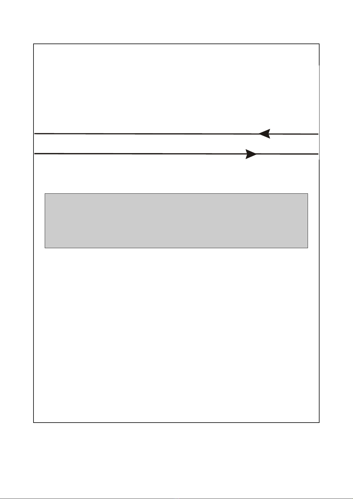
ATM CBR DSUs are used to connect equipment which operates at constant bit rates (CBR),
such as PABXs and Video Codecs, across ATM networks. The DSUs are used in pairs, one
at either side of a Wide Area Network (WAN) link.
Since ATM is a bandwidth independent transmission mechanism, the circuit information is
segmented into ATM cells, passed across the network and then reassembled into the
original bit pattern. The ATM CBR DSU uses AAL1 Segmentation and Re-assembly for
conversion of the CBR stream into a stream of ATM cells, and vice versa.
Note that the ATM WAN links can operate with different interfaces to the CBR source,
providing that sufficient bandwidth is available on the ATM (or WAN) side to service the CBR
stream when the ATM overhead is taken into account. This means that the ATM side of the
DSU must present a higher bandwidth than the CBR side.
Figure 1.1 Bandwidth for CBR to ATM conversion
The table above simply illustrates the raw bandwidth required to convert CBR traffic into
ATM traffic. Note that the payload in each ATM cell is 47 bytes because 1 byte is used for
AAL1 segmentation/re-assembly.
Also, the effect of any ATM framing will increase the required bandwidth on the ATM side by
a further 1.3% for E3 UNI ports and 2% for DS3 UNI ports.
The ATM CBR DSU presents two types of interface:
A CBR interface providing a choice of E1, E2, E3 or DS3 lines connects to the CBR (constant
bit rate) equipment. The DSU front panel indicates this as the LINE port.
A User Network Interface (UNI) connects to the ATM WAN network providing a choice of E3,
DS3, TAXI and SDH/SONET interfaces. The ATM CBR DSU front panel indicates this as the
ATM UNI port.
CBR Link
Type
CBR Speed
Mbits/sec
ATM Cells/sec
Generated
Raw WAN ATM Bandwidth
required Mbits/sec
E1 2⋅048 5447 2.309
E2 8⋅448 22469 9.526
E3 34⋅368 91404 38.755
DS3 44.736 118978 50.446

INTRODUCTION
76-02-031E 2
Metrodata ATM CBR DSUs also provide extensive performance monitoring facilities. They
can monitor degraded line performance and traffic density and have extended alarm
processing on the connection, giving the network manager visibility and control of the wide-
area link.
A record is kept of all error conditions, including major and minor alarms and bit errors, for
the last 24 hours. Statistics are recorded every 15 minutes and processed into G.821 format.
Ninety-six 15-minute periods are kept, which means that 24-hour coverage is maintained on
a rolling basis.
Diagnostics are provided in the form of various loop-backs which can be used to localise a
fault condition on the line.
ATM CBR DSUs can be managed by connecting a video terminal to the DSU, either directly
through a serial interface, or via a multiplexer or modem.
The LM1100 SNMP Enabler option is fitted as standard on all units. This means that ATM
CBR DSUs can be managed remotely with a Simple Network Management Protocol (SNMP)
management system connected to the LAN. Telnet access can also be achieved through the
LM1100 SNMP Enabler.
Finally, with a video terminal connected to the serial interface port, a DSU can double as a
terminal adapter and hence connection may be made to remote Telnet-accessible devices
via the Management port.
INTRODUCTION
3 76-02-031E
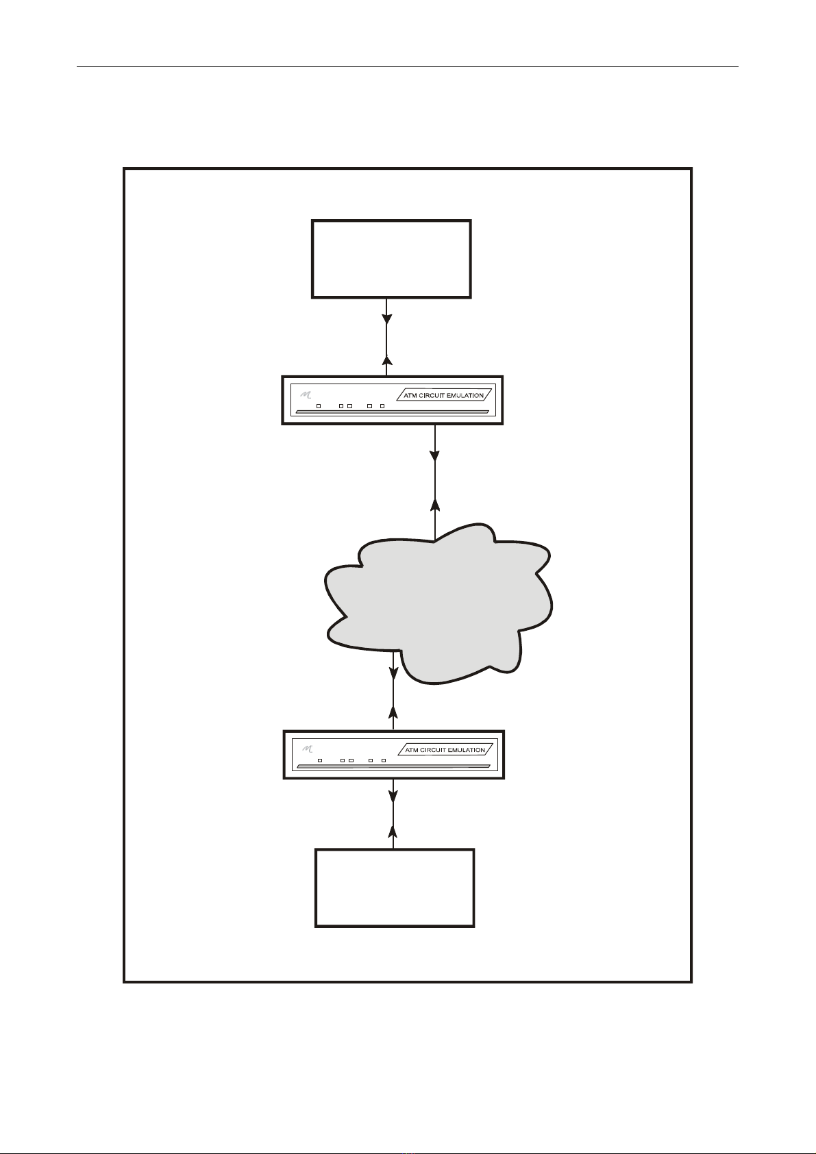
1. 2 ATM CBR DSU Typical Installation
The DSUs are installed in-circuit as shown in the Figure below:
Figure 1.2 ATM CE Deployment
WAN
PABX /
VIDEO CODEC
PABX /
VIDEO CODEC
A
TM CBR DSU
E1 CBR LINK
E3 ATM LINK
A
TM NETWORK
DS3 ATM LINK
E1 CBR LINK
ATM CBR DSU
ATM UNI PORT
LINE PORT
ATM UNI PORT
LINE PORT

INTRODUCTION
76-02-031E 4
1. 3 About this manual
This user manual describes the installation, commissioning and operation of the ATM CBR
DSU family at firmware version 3.9 and version 4.0.
The manual assumes a certain level of knowledge on the part of the reader, such as basic
communications and networking concepts and terminology. However, a glossary is provided
which explains the abbreviations introduced by this manual.
It is important that you read and understand the performance and operating limitations in
Section 2, Statutory Information and the Specifications in Section 16 of the DSU before
attempting any connections.
Section 3, Introducing the ATM CBR DSU provides a technical overview of the ATM CBR
DSU family of products and their fascia panels and interfaces.
Section 4, Installing and Setting-up, takes you through the basic steps of connecting the
DSU to the external devices that you may have.
Section 5, Configuring the ATM CBR DSU, describes the menu-driven user interface. The
end of this Section describes a typical set-up and commissioning procedure, and acts as a
checklist for both first-time and experienced users of the DSU.
Section 6, Analysing Performance shows how to monitor the line performance and change
the summary report options
Section 7 introduces the concept of Remote Management of the DSU using Simple Network
Management Protocol with the LM1100 SNMP Enabler. However this subject is too detailed
to be described in this manual, and you should refer to the LM1100 user manual.
The Testing and diagnostic functions of the DSU are described in Section 8, including testing
the local and remote connections. The troubleshooting section is provided in the form of a
checklist to assist you.
Sections 9 to 12 describe each of the Circuit Emulation (CBR) interfaces available for the
ATM CBR DSU family of products. Sections 13 to 16 inclusive describe the UNI (or WAN)
interfaces.
Finally, Section 17 lists the various Specifications of the DSU interfaces. The data in this
section may be needed to set-up the ATM CBR DSU.

INTRODUCTION
5 76-02-031E
1. 4 Conventions
Notes are used to provide the reader with either statutory information which must be
observed for safety reasons, or additional information which may increase the DSUs
effectiveness.
A pair of arrows around a word indicates a key on the keyboard, such as <space> or
<escape>.
There are two exceptions to this, which appear on some of the menus:
<display> indicates that selecting the option will lead to data being displayed on the screen.
<menu> indicates that the option leads to another menu, from which further options may be
chosen.
Screen displays which contain variable information, such as the current date or time, show
the variable in italics, surrounded by square brackets, i.e. [time], or “[nodename]”. The
inverted commas indicate data inserted by the user. Where menu items are referred to in the
text, they are printed in italics to assist the user to cross relate to screen examples in figures.
Screen examples. The DSUs allow you to use any one of three options for displaying the
menus on a terminal - ANSI, VT100/VT220 or TTY.
The screen examples in this manual use VT100/VT220 and are shaded to allow easy
identification by the reader.

INTRODUCTION
76-02-031E 6

STATUTORY INFORMATION
7 76-02-031E
2 STATUTORY INFORMATION
The ATM CBR DSU family Line Ports comply with the requirements of G.703
at 2⋅048 Mbit/s (E1), 8⋅448 Mbit/s (E2), 34⋅368 Mbit/s (E3) and 44⋅736 Mbit/s (DS3).
ATM CBR DSU family products should not be connected to cabling which would be required
by BS6701 to be equipped with over-voltage protection.
2. 1 Safety
The following ports are designated SELV (Safety Extra Low Voltage) within the scope of
EN41003:
CBR LINE port
ATM UNI port
Terminal port
Management port
Alarm extension port
Users are reminded that these ports should only be connected to SELV ports on other
equipment in accordance with EN60950 clause 2.3.
2.2 Electromagnetic Compatibility
In order to ensure EMC compliance all signal and data cables and connectors must use a
screened connector shell with a screened cable. The cable screen must be terminated to the
screened connector shell and not connected to any pins of the connector. Failure to use the
correct connector may compromise EMC compliance.
2. 3 EN55022 Declaration
The ATM CBR DSU is a Class A product. In a domestic environment it may cause radio
interference in which case the user may be required to take adequate measures.
2. 4 FCC Declaration
This equipment has been tested and found to comply with the limits for a Class A digital
device, pursuant to Part 15 of the FCC Rules. These limits are designed to provide
reasonable protection against harmful interference when the equipment is operated in a
commercial environment. This equipment generates, uses, and can radiate radio frequency
energy and, if not installed and used in accordance with the instruction manual, may cause
harmful interference to radio communications. Operation of this equipment in a residential
area is likely to cause harmful interference in which case the user will be required to correct
the interference at its own expense.

STATUTORY INFORMATION
76-02-031E 8
2. 5 Power Supply
The ATM CBR DSU is powered by a mains supply with an input voltage of 100-250VAC 50-
400Hz and with an input current of 50 mA. The unit is provided ex-factory with a 250mA
internal fuse. Mains power is connected via the IEC inlet on the rear of the unit.
An alternative -48VDC powered unit is available. The input voltage and current ranges are
minus 36 to minus 72 volts DC, 200 - 100mA. A Buccaneer type socket is fitted to the rear
panel, and a plug is provided with the unit for the customer’s own wiring. The connections
are labelled on the rear panel of the LH1000.
On some units, an additional Ground stud may be located on the rear panel to permit a
separate Ground connection to be made.
Figure 2. 1 -48VDC connections
Note: The ATM CBR DSU must be connected to safety earth for correct operation.
Safety notes:
Excessive voltages are present inside the unit. There are no user serviceable parts inside
the unit, and the cover should not be removed by unqualified personnel. The unit must not
be exposed to damp or condensing conditions. The unit must be connected to safety earth
for correct operation.
2. 6 On-board batteries
The user is reminded that DSU motherboards use Lithium/Thionyl Chloride 3.6 volt battery
cells for maintenance of RAM based data when power is removed from the unit
These batteries must be handled with care. There may be a risk of explosion if a battery is
incorrectly replaced. Do not recharge, force open, heat or dispose of by fire. Replace only
with the same type of battery. Disposal must be in accordance with the manufacturer’s
instructions. If in doubt about any aspect of battery replacement or disposal, please call
Metrodata Technical Support department.
Pin no Connection
1-48VDC
2 Ground
30VDC
STATUTORY INFORMATION
9 76-02-031E
2. 7 Laser Technology
The user is reminded that some models of the ATM CBR DSU family employ laser
technology. Care must be taken not to expose the eyes to laser beams or radiation since
tissue damage to the eyes can result. DSUs that use laser technology are the SDH/Sonet
models. The rear panels of all models using laser technology are marked with a label as
shown below:
Figure 2.2

STATUTORY INFORMATION
76-02-031E 10
Table of contents
Other Metrodata Network Hardware manuals


Popular Network Hardware manuals by other brands


Seenergy
Seenergy SVR-632/664 user manual

ATTO Technology
ATTO Technology iSCSI Bridge 2600C Specification sheet

Nvidia
Nvidia BlueField-3 user guide

Gossen MetraWatt
Gossen MetraWatt KONSTANTER SPL Series operating instructions

Media Links
Media Links MD8000 Series Operational manual

Direct IP
Direct IP IDIS DR-1300 Series quick guide


