Table of Contents
© 2019 Valeport Ltd Page 2
Table of Contents
..................................................................................................................................... 41. EU Declaration of Conformity - CE Marking
..................................................................................................................................... 72. Introduction
.................................................................................................................................... 72.1. rapidPro SVT
2.1.1 Sensor Specifications
.................................................................................................................................... 8
2.1.2 Dimensions
.................................................................................................................................... 9
.................................................................................................................................... 102.2. rapidPro CTD and rapidPro CTDplus
2.2.1 Sensor Specifications
.................................................................................................................................... 11
2.2.2 Fluorometers
.................................................................................................................................... 12
2.2.3 Linear Observation Range
.................................................................................................................................... 14
2.2.4 Quenching
.................................................................................................................................... 15
2.2.5 Turbidity
.................................................................................................................................... 16
2.2.6 Dimensions
.................................................................................................................................... 17
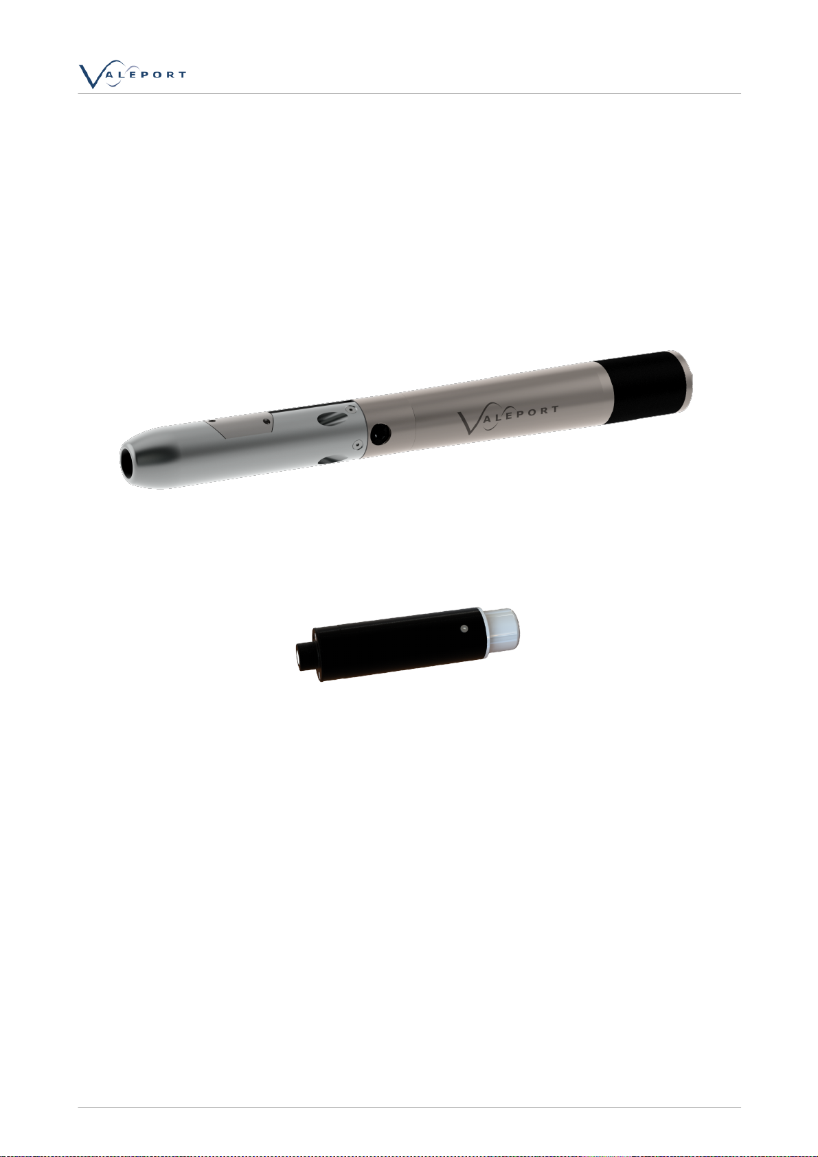
.................................................................................................................................... 182.3. ProLogger
2.3.1 Changing\Charging the ProLogger
.................................................................................................................................... 19
2.3.2 ProLogger Dimensions
.................................................................................................................................... 20
2.3.3 Rechargeable Battery
.................................................................................................................................... 20
..................................................................................................................................... 233. Communication | Memory | Software
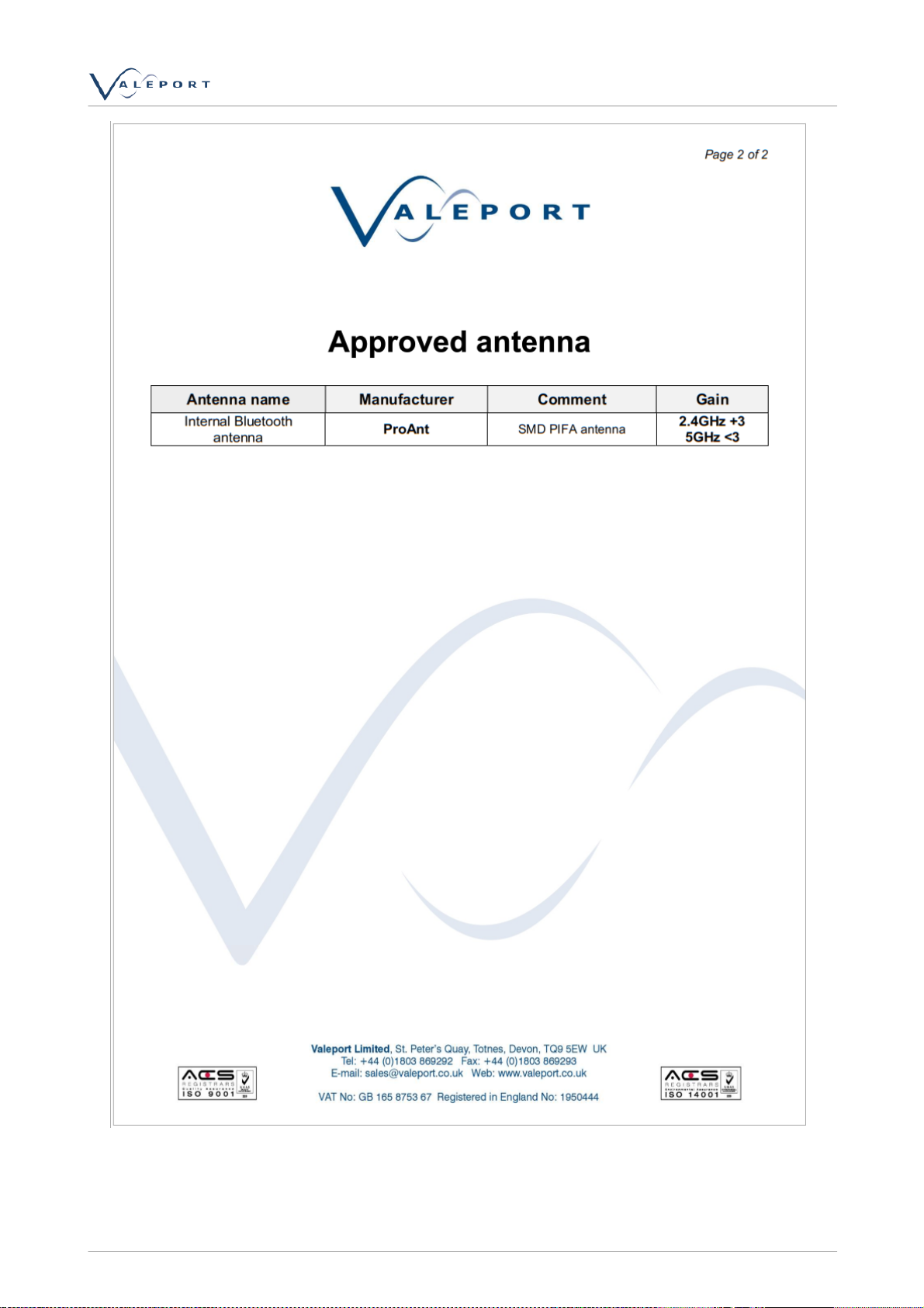
.................................................................................................................................... 233.1. Qualification and Approvals-Bluetooth Module
3.1.1 Compliance with RoHS Directive
.................................................................................................................................... 24
3.1.2 European Union Regulatory Compliance - Bluetooth Module
.................................................................................................................................... 25
3.1.3 Bluetooth Qualification Information
.................................................................................................................................... 26
..................................................................................................................................... 274. Operation
.................................................................................................................................... 274.1. Operating Modes
.................................................................................................................................... 284.2. Switching On/Off
.................................................................................................................................... 294.3. Deployment
.................................................................................................................................... 294.4. Pressure Tare
.................................................................................................................................... 304.5. Data Requests and Output Formats
4.5.1 Stop Command
.................................................................................................................................... 30
4.5.2 Run Commands
.................................................................................................................................... 30
4.5.3 Rapid Profile Settings
.................................................................................................................................... 31
4.5.4 Site information
.................................................................................................................................... 31
4.5.5 Instrument Information
.................................................................................................................................... 31