S+S REGELTECHNIK GMBH |THURN-UND-TAXIS-STR. 22 |D-90411 NÜRNBERG |GERMANY |FON +49 (0) 911 51947- 0 |www.S plusS.de
5
Operating instructions
RYMASKON®600 - BACnet
RYMASKON®600 - Modbus
The
RYMASKON
®
500
/
600
/
700
series of room control units are designed for controlling the climatic
zone in residential, hotel and office rooms and individually regulate the heating/cooling steps of the internal
rooms. A colour touch display with modern icons is used for the visual display and operation at the location.
The product range is characterised by the variety of combination options of the individual components.
The
RYMASKON
®
600
Controller
series regulates through analogue outputs (0–10 V) up to two
heating
or cooling valves
(6-way valves can also be controlled) and the
fan
(EC ventilator).
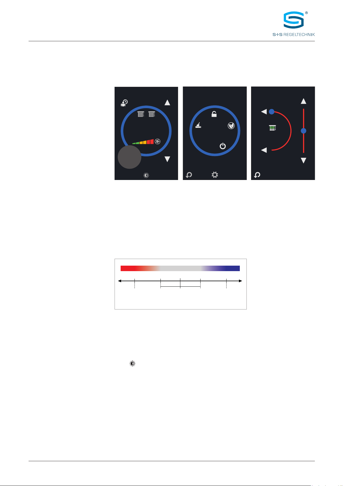
The
sun protection
(blinds, shutters) can be controlled in two zones via the bus. Through the appropriate
symbols, it is possible to control the
light
instead of the sun protection.
In addition to the integrated temperature sensor, two external temperature sensors (NTC10K) or two
analogue sensors (0–10V) can also be connected. Measuring elements for relative humidity and CO2 are
also available. The devices are used in room climate technology, including convector fans, cooling ceilings
and heating/cooling systems. Wall mounting is performed on standard in-wall flush boxes. The devices are
optionally available with a Modbus or BACnet communication interface and in various type versions (see
number key).
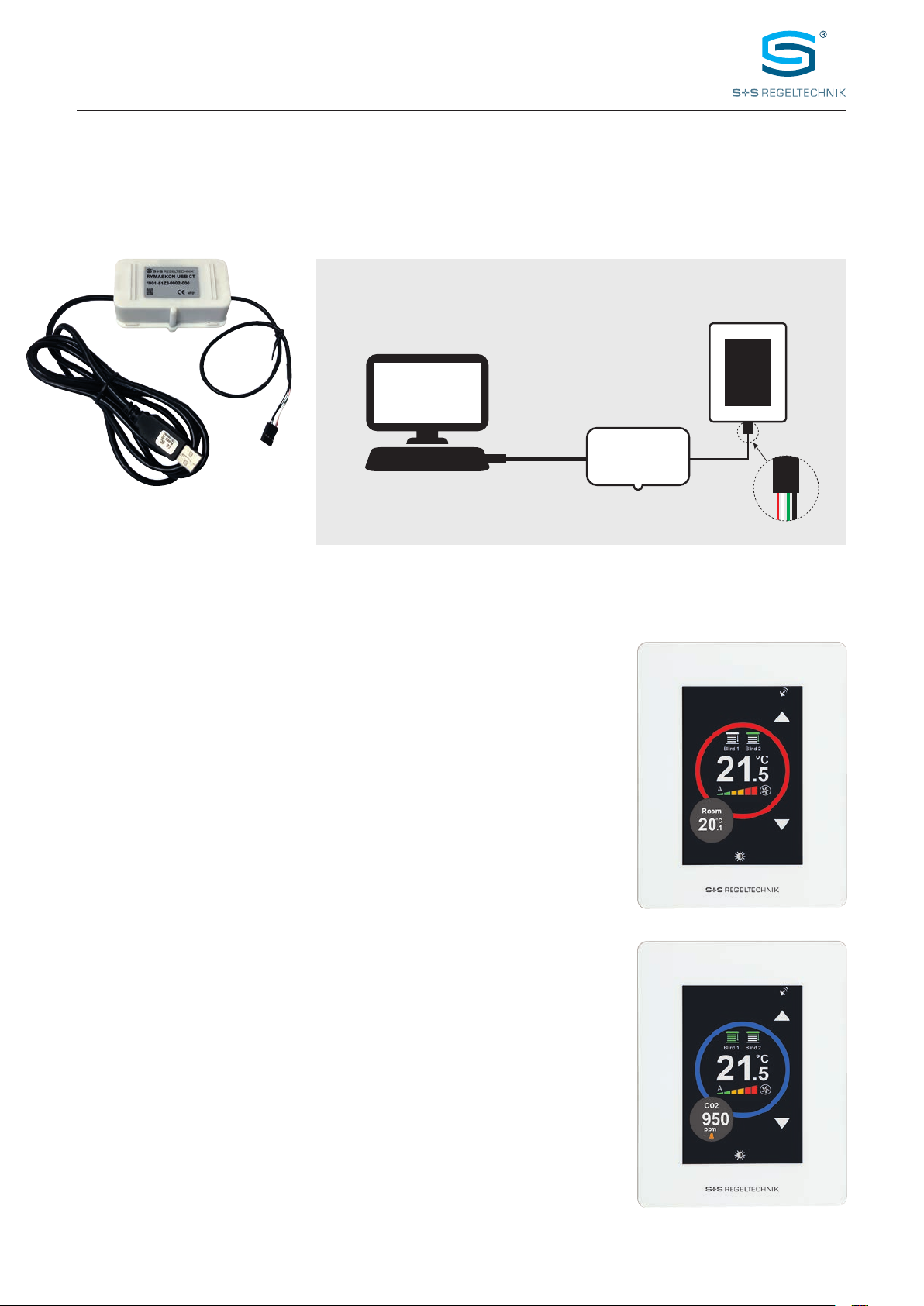
The basic model
RYMASKON
®
610
Controller
with colour touch display (3.5"), in a white housing,
possesses an integrated temperature and humidity sensor (CO2 sensor optional), 2 analogue inputs for
external sensors (0–10 V), 1 digital input, 3 analogue outputs (0–10 V), and optionally with Modbus or
BACnet connection. The room control units are used for controlling temperature, fan, light (1 zone) and
sun protection (2 zones) directly via the analogue outputs or via the bus.
TECHNICAL DATA (Basic model)
Device type: room control unit with controller
Functions: temperature, fan, light (1 zone),
and sun protection (2 zones)
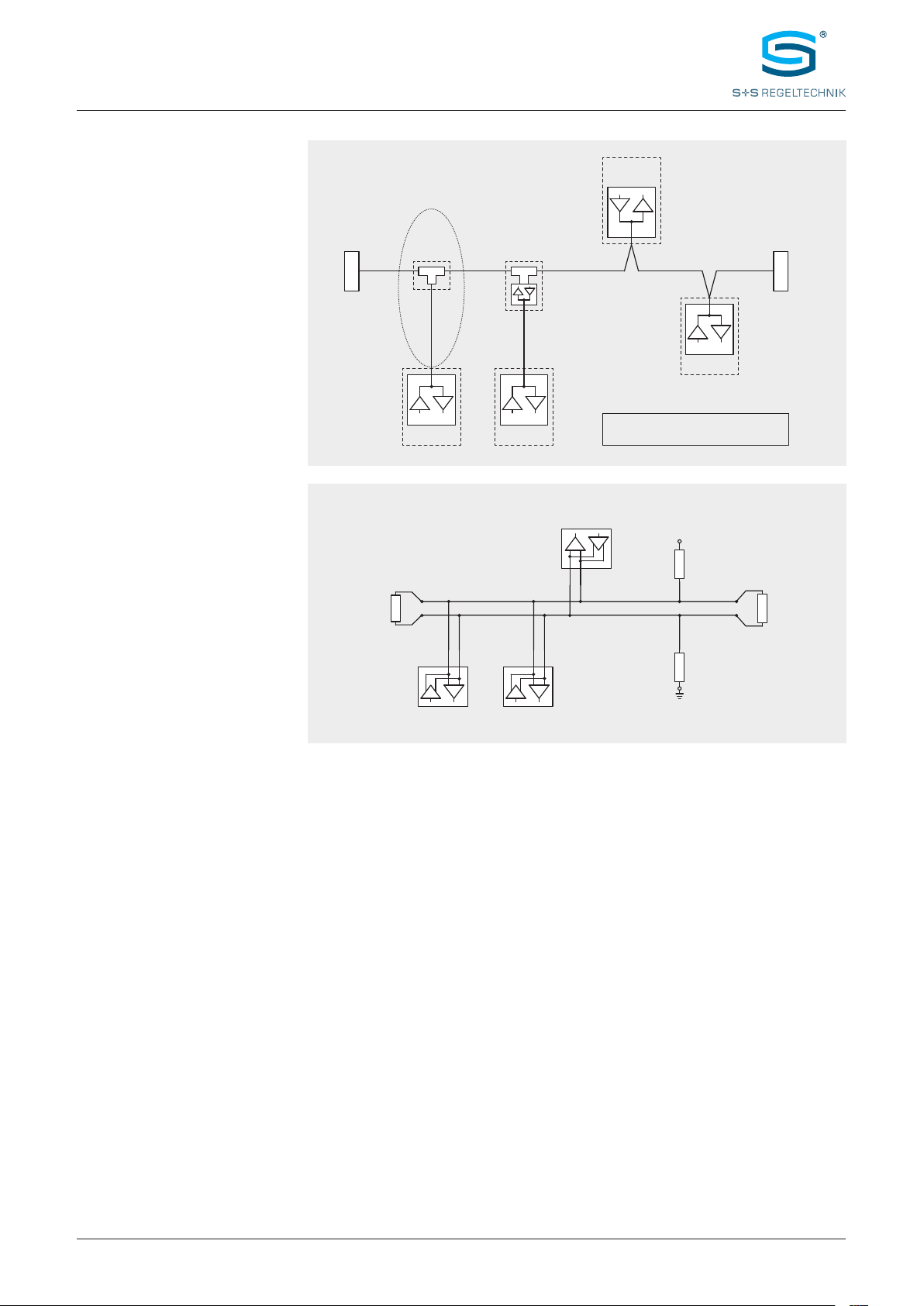
Communication:
Modbus RTU Slave
address range can be configured between 1...247
or
BACnet MS
/
TP
device ID 65100 (default) and MAC address can be configured between
1...127
RS 485 interface, max. 63 devices,
9600 / 19200 / 38400 / 57500 / 76800 Baud,
none / even / odd parity, 1 / 2 stop bits
Power supply: 24 V AC/DC (± 15 %)
Power consumption: max. 1.92 W
Inputs: 2 analogue inputs 0–10V
1 digital input (potential-free), Impedance <1kOhm
Outputs: 3 analogue outputs 0–10V (heating, cooling, fan)
input impedance > 100kOhm
Operating mode: Comfort, ECO, OFF, Boost, Frost Protection
Control element:
3.5" touch display
with backlighting,
cut-out approx. 50 x 75 mm, resolution 320 x 480 pixels, 255,000 colours
TEMPERATURE
Sensor: integrated temperature sensor
Measuring range: –40...+125 °C
Accuracy: typically ±0.5 °C at +25 °C
HUMIDITY
Sensor: integrated humidity sensor
Measuring range: 0...100 % r.H.
Accuracy: typically ±2 % r.H. (20...80 % r.H.) at +25 °C
CARBON DIOXIDE (CO2)
Sensor: optical NDIR sensor (non-dispersive infrared technology),
with automatic calibration
Measuring range: 0...5000 ppm
Accuracy: typically ±50 ppm ±3 % of the measured value at +25 °C
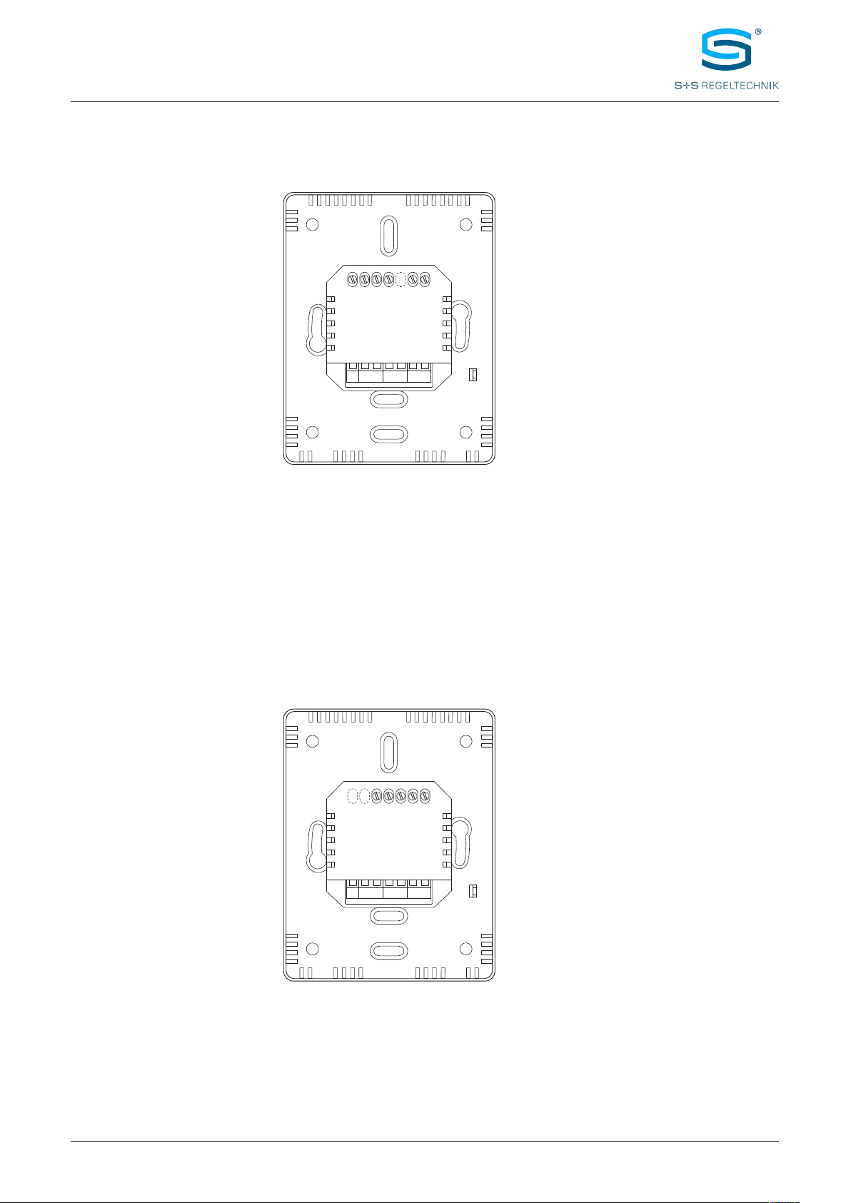
Electrical connection: 0.14–1.5mm², via screw terminals
Housing: plastic, polycarbonate material, self-extinguishing,
white colour (optionally black or chrome), weight approx. 220g
Housing dimensions: approx. 88 x 112 x 14.5 mm (on-wall)
approx. 88 x 112 x 20.5 mm (on-wall with CO2 sensor)
approx. 52 x 53 x 28.5 mm (in-wall)
Mounting: wall mounting on in-wall flush box, Ø 55mm
Ambient temperature: 0...+50°C (operation); –30...+70°C (storage)
Permitted humidity: 0...95 % r. H., (non-precipitating air)
Protection type:
IP 20
(
according to
EN 60 529)
Standards: CE conformity,
according to EMC directive 2004/108/EU, Low-Voltage directive 2006/95/EU,
according to
EN 61000-6-1/3, EN 60730-1, EN 6100-4-2/4/5/11
DESCRIPTION
Introduction and
technical data