Metrohm IC Conductivity Detector User manual

IC Professional Detector
IC Conductivity Detector
Manual
8.850.8057EN


Metrohm AG
CH-9101 Herisau
Switzerland
Phone +41 71 353 85 85
Fax +41 71 353 89 01
www.metrohm.com
IC Professional Detector
IC Conductivity Detector
2.850.9010
Manual
8.850.8057EN 04.2010 zst

Teachware
Metrohm AG
CH-9101 Herisau
This documentation is protected by copyright. All rights reserved.
Although all the information given in this documentation has been
checked with great care, errors cannot be entirely excluded. Should you
notice any mistakes please send us your comments using the address
given above.
Documentation in additional languages can be found on
http://products.metrohm.com under Literature/Technical documenta-
tion.

■■■■■■■■■■■■■■■■■■■■■■ Table of contents
2.850.9010 IC Conductivity Detector ■■■■■■■■ III
Table of contents
1 Introduction 1
1.1 Instrument description ......................................................... 1
1.2 Overview of the instrument ................................................. 2
1.2.1 Front ...................................................................................... 2
1.2.2 Rear ....................................................................................... 3
1.3 Intended use ......................................................................... 3
1.4 About the documentation ................................................... 4
1.4.1 Symbols and conventions ........................................................ 4
1.5 Safety instructions ................................................................ 5
1.5.1 General notes on safety ........................................................... 5
1.5.2 Electrical safety ........................................................................ 5
1.5.3 Working with liquids ................................................................ 6
1.5.4 Recycling and disposal ............................................................. 6
2 Installation 7
2.1 Setting up the instrument .................................................... 7
2.1.1 Packaging ................................................................................ 7
2.1.2 Checks .................................................................................... 7
2.1.3 Location .................................................................................. 7
2.2 Inserting the detector .......................................................... 7
2.3 Connecting the detector .................................................... 10
2.4 Connecting the detector inlet capillary ............................ 11
3 Start-up 13
4 Operation and maintenance 14
4.1 Maintenance ....................................................................... 14
4.2 Quality Management and validation with Metrohm ....... 14
5 Troubleshooting 16
5.1 Problems and their solutions ............................................. 16
6 Technical specifications 17
6.1 Technical specifications ..................................................... 17
7 Conformity and warranty 18
7.1 Quality Management Principles ........................................ 18
7.2 Warranty (guarantee) ......................................................... 19

■■■■■■■■■■■■■■■■■■■■■■ Table of figures
2.850.9010 IC Conductivity Detector ■■■■■■■■ V
Table of figures
Figure 1 Front ................................................................................................ 2
Figure 2 Rear ................................................................................................. 3
Figure 3 Inserting the detector ........................................................................ 8
Figure 4 Connection detector – separation column ....................................... 11
Figure 5 Connector detector – MSM ............................................................. 12
Figure 6 Connection detector – MCS ............................................................ 12


■■■■■■■■■■■■■■■■■■■■■■ 1 Introduction
2.850.9010 IC Conductivity Detector ■■■■■■■■ 1
1 Introduction
1.1 Instrument description
The IC Conductivity Detector is an intelligent conductivity detector for
usage in the instruments of the 850 Professional IC, the 881 Compact IC
pro and the 882 Compact IC plus line of instruments.
The IC Conductivity Detector continuously measures the conductivity of
the liquid passing through and indicates these signals in digital form (DSP
– Digital Signal Processing). The conductivity detector exhibits outstanding
thermal stability and thus guarantees reproducible measuring conditions.
The IC Conductivity Detector can only be used together with the IC instru-
ment. The software MagIC Net automatically recognizes the IC Conduc-
tivity Detector and checks its functional readiness. It controls and monitors
all the instruments connected, evaluates the measured data and adminis-
ters it in a database. The operation of MagIC Net is described in the online
help and in the tutorial for MagIC Net.

1.2 Overview of the instrument ■■■■■■■■■■■■■■■■■■■■■■
2■■■■■■■■ 2.850.9010 IC Conductivity Detector
1.2 Overview of the instrument
1.2.1 Front
2
1
3
Figure 1 Front
1IC detector 2.850.9010 2Opening for temperature sensor
3Detector inlet capillary
Permanently installed.

■■■■■■■■■■■■■■■■■■■■■■ 1 Introduction
2.850.9010 IC Conductivity Detector ■■■■■■■■ 3
1.2.2 Rear
1
3
2
Figure 2 Rear
1Detector cable
With mounted plug.
2Detector outlet capillary
Permanently installed.
3Type plate
With serial number.
1.3 Intended use
The IC Conductivity Detector can only be used together with an IC instru-
ment. It is used for the precise measurement of the conductivity during
the ion chromatographic determination of cations and anions.
As the corresponding IC instrument, the IC Conductivity Detector is also
suitable for processing chemicals and flammable samples. The usage of
the IC Conductivity Detector therefore requires that the user has basic
knowledge and experience in the handling of toxic and caustic substan-
ces. Knowledge with respect to the application of the fire prevention
measures prescribed for laboratories is also mandatory.

1.4 About the documentation ■■■■■■■■■■■■■■■■■■■■■■
4■■■■■■■■ 2.850.9010 IC Conductivity Detector
1.4 About the documentation
CAUTION
Please read through this documentation carefully before putting the
instrument into operation. The documentation contains information
and warnings which the user must follow in order to ensure safe opera-
tion of the instrument.
1.4.1 Symbols and conventions
The following symbols and styles are used in this documentation:
Cross-reference to figure legend
The first number refers to the figure number, the
second to the instrument part in the figure.
Instruction step
Carry out these steps in the sequence shown.
Warning
This symbol draws attention to a possible life hazard
or risk of injury.
Warning
This symbol draws attention to a possible hazard due
to electrical current.
Warning
This symbol draws attention to a possible hazard due
to heat or hot instrument parts.
Warning
This symbol draws attention to a possible biological
hazard.
Caution
This symbol draws attention to a possible damage of
instruments or instrument parts.
Note
This symbol marks additional information and tips.

■■■■■■■■■■■■■■■■■■■■■■ 1 Introduction
2.850.9010 IC Conductivity Detector ■■■■■■■■ 5
1.5 Safety instructions
1.5.1 General notes on safety
WARNING
This instrument may only be operated in accordance with the specifica-
tions in this documentation.
This instrument has left the factory in a flawless state in terms of technical
safety. To maintain this state and ensure non-hazardous operation of the
instrument, the following instructions must be observed carefully.
1.5.2 Electrical safety
WARNING
Only personnel qualified by Metrohm are authorized to carry out service
work on electronic components.
WARNING
Never open the housing of the instrument. The instrument could be
damaged by this. There is also a risk of serious injury if live components
are touched.
There are no parts inside the housing which can be serviced or replaced
by the user.
Protection against electrostatic charges
WARNING
Electronic components are sensitive to electrostatic charges and can be
destroyed by discharges.
Always pull the mains cable out of the mains connection socket before
connecting or disconnecting electrical appliances on the rear panel of
the instrument.

1.5 Safety instructions ■■■■■■■■■■■■■■■■■■■■■■
6■■■■■■■■ 2.850.9010 IC Conductivity Detector
1.5.3 Working with liquids
CAUTION
Periodically check all system connections for leaks. Observe the relevant
regulations in respect to working with flammable and/or toxic fluids
and their disposal.
1.5.4 Recycling and disposal
This product is covered by European Directive 2002/96/EC, WEEE – Waste
from Electrical and Electronic Equipment.
The correct disposal of your old equipment will help to prevent negative
effects on the environment and public health.
More details about the disposal of your old equipment can be obtained
from your local authorities, from waste disposal companies or from your
local dealer.

■■■■■■■■■■■■■■■■■■■■■■ 2 Installation
2.850.9010 IC Conductivity Detector ■■■■■■■■ 7
2 Installation
2.1 Setting up the instrument
2.1.1 Packaging
The instrument is supplied in highly protective special packaging. Keep this
packaging, as only this ensures safe transportation of the instrument.
2.1.2 Checks
Immediately after receipt, check whether the shipment has arrived com-
plete and without damage by comparing it with the delivery note. In the
case of damage during transportation, see the notes in chapter 7.2War-
ranty (guarantee); page 19.
2.1.3 Location
The IC Conductivity Detector is designed for usage in the detector cham-
ber of the IC instruments. For the location, the same conditions apply as
for the IC instrument.
2.2 Inserting the detector
The IC Conductivity Detector is inserted into the instruments from the
rear.
Figure 3 shows how the detector is inserted into an 850 Professional IC
instrument within 6 simple steps. Inserting the detector into an 881 Com-
pact IC pro or 882 Compact IC plus instrument is carried out analogously.

2.2 Inserting the detector ■■■■■■■■■■■■■■■■■■■■■■
8■■■■■■■■ 2.850.9010 IC Conductivity Detector
2
34
5
1
1
2
Figure 3 Inserting the detector
1Detector connection cable 2Detector outlet capillary

■■■■■■■■■■■■■■■■■■■■■■ 2 Installation
2.850.9010 IC Conductivity Detector ■■■■■■■■ 9
NOTE
With the instruments of the 850 Professional line of instruments, up to
two detectors can be placed and connected.
Placing the detector in the instrument
1Removing the knurled screws
■Unscrew knurled screws on the rear panel.
■Optional with 850 instruments: Remove the handle if it is still fas-
tened to the instrument.
2Removing rear panel
■Remove rear panel.
3Positioning the detector
■Put the detector through the opening and position it on the sup-
port surface intended for this purpose and slide it as far as the
limit stop to the front.
4Replacing rear panel
■Insert the detector cable in a cable feed-through on the rear
panel.
■Place the detector outlet capillary in a suitable capillary feed-
through.
■Replacing the rear panel.
The detector cable (3-1) and the detector outlet capillary (3-2)
should freely hang out of the cable or capillary feed-through.
5Tightening the knurled screws
■Optional with 850 instruments: Reattach the handle higher up
and use it as a holder for MPaks.
■Tighten the knurled screws.

2.3 Connecting the detector ■■■■■■■■■■■■■■■■■■■■■■
10 ■■■■■■■■ 2.850.9010 IC Conductivity Detector
2.3 Connecting the detector
Connecting the detector cable and the detector outlet
capillary
CAUTION
The instrument must be switched off when connecting a detector.
1Connecting the detector
■Connect the detector connection cable (3-1) to the detector con-
nection socket Detector 1.
NOTE
Recommendation: In AnCat systems with 2 detectors: anions to
Detector 1, cations to Detector 2.
2Connecting the detector outlet capillary
■Guide the detector outlet capillary (3-2) into a sufficiently large
waste container and fasten it there.
NOTE
The detector outlet capillary must be free of blockages (the mea-
suring cell is tested to 5 MPa = 50 bar backpressure).
NOTE
The detector outlet capillary must not be shortened!
Shortening the detector outlet capillary leads to increased noise!

■■■■■■■■■■■■■■■■■■■■■■ 2 Installation
2.850.9010 IC Conductivity Detector ■■■■■■■■ 11
2.4 Connecting the detector inlet capillary
Depending on the equipment of the IC instruments the detector inlet
capillary is connected differently:
■With instruments without suppression, directly to the separation col-
umn (see "Connect the detector inlet capillary to the separation col-
umn", page 11).
■With instruments with chemical suppression, to the MSM or MSM-HC
(see "Connecting detector inlet capillary to MSM / MSM
‑
HC", page
12).
■With instruments with sequential suppression, to the MCS (see "Con-
necting the detector inlet capillary to the MCS", page 12).
NOTE
In order to prevent unnecessary peak widening after separation, the
connection between the outlet of the separation column and the inlet
in the detector should be kept as short as possible.
Connect the detector inlet capillary to the separation col-
umn
1Connecting detector input
■Fasten the detector inlet capillary (4-1) on the output of the col-
umn (4-3) using a 6.2744.070 pressure screw (4-2).
1
2
3
Figure 4 Connection detector – separation column
1Detector inlet capillary 2PEEK pressure screw, short 6.2744.070
3Separation column

2.4 Connecting the detector inlet capillary ■■■■■■■■■■■■■■■■■■■■■■
12 ■■■■■■■■ 2.850.9010 IC Conductivity Detector
Connecting detector inlet capillary to MSM / MSM-HC
1Connecting detector input
■Connect the detector inlet capillary (5-1) and the capillary of the
MSM / MSM-HC (5-2) labeled with out to one another using a
6.2744.040 coupling (5-3) and two 6.2744.070 short pressure
screws (5-4).
1 2
3
4
Figure 5 Connector detector – MSM
1Detector inlet capillary 2MSM / MSM-HC outlet capillary
labeled with out.
3Coupling 6.2744.040 4Pressure screws, short 6.2744.070
Connecting the detector inlet capillary to the MCS
1Connecting detector input
■Fasten the detector inlet capillary (6-1) using a 6.2744.090 long
PEEK pressure screw (6-2) on the output of the MCS (6-3).
3 2 1
Figure 6 Connection detector – MCS
1Detector inlet capillary 2Pressure screw, long 6.2744.090
3MCS output
Other manuals for IC Conductivity Detector
1
This manual suits for next models
1
Table of contents
Other Metrohm Security Sensor manuals
Metrohm
Metrohm Vario-SW 947 Series User manual
Metrohm
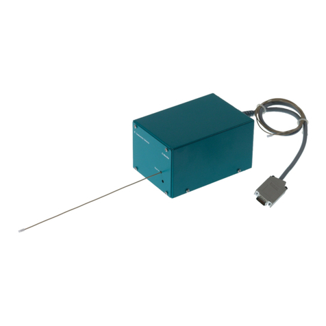
Metrohm IC Conductivity Detector User manual
Metrohm
Metrohm MB User manual
Metrohm
Metrohm 944 User manual

Metrohm
Metrohm 887 User manual

Metrohm
Metrohm 945 Professional Detector Vario User manual
Metrohm
Metrohm 896 User manual
Metrohm
Metrohm IC Amperometric Detector User manual

