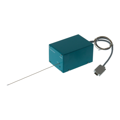
Metrohm MB User manual

IC Professional Detector
IC Conductivity Detector MB
Manual
8.850.8065EN / 2022-11-15


Metrohm AG
CH-9100 Herisau
Switzerland
+41 71 353 85 85
www.metrohm.com
IC Professional Detector
IC Conductivity Detector MB
2.850.9020
Manual
8.850.8065EN / 2022-11-15

Technical Communication
Metrohm AG
CH-9100 Herisau
This documentation is protected by copyright. All rights reserved.
This documentation has been prepared with great care. However, errors
can never be entirely ruled out. Please send comments regarding possible
errors to the address above.
Disclaimer
Deficiencies arising from circumstances that are not the responsibility of
Metrohm, such as improper storage or improper use, etc., are expressly
excluded from the warranty. Unauthorized modifications to the product
(e.g. conversions or attachments) exclude any liability on the part of the
manufacturer for resulting damage and its consequences. Instructions and
notes in the Metrohm product documentation must be strictly followed.
Otherwise, Metrohm's liability is excluded.

■■■■■■■■■■■■■■■■■■■■■■ Table of contents
2.850.9020 IC Conductivity Detector MB ■■■■■■■■ III
Table of contents
1 Introduction 1
1.1 Instrument description ......................................................... 1
1.2 Overview of the instrument ................................................. 2
1.2.1 Front ....................................................................................... 2
1.2.2 Rear ........................................................................................ 3
1.3 Accessories and additional information ............................. 3
1.4 About the documentation ................................................... 4
1.4.1 Symbols and conventions ........................................................ 4
2 Safety 5
2.1 Intended use ......................................................................... 5
2.2 Responsibility of the operator ............................................. 5
2.3 Requirements for operating personnel ............................... 6
2.4 Safety instructions ................................................................ 6
2.4.1 General notes on safety ........................................................... 6
2.4.2 Electrical safety ........................................................................ 6
2.4.3 Working with liquids ................................................................ 7
2.4.4 Recycling and disposal ............................................................. 7
3 Installation 8
3.1 Setting up the instrument .................................................... 8
3.1.1 Packaging ................................................................................ 8
3.1.2 Check ...................................................................................... 8
3.1.3 Location .................................................................................. 8
3.2 Inserting the detector .......................................................... 8
3.3 Connecting the detector .................................................... 11
3.4 Connecting the detector inlet capillary ............................ 12
3.5 Connecting the instrument to the power grid ................. 14
4 Start-up 15
5 Operation and maintenance 16
5.1 Maintenance ....................................................................... 16
6 Troubleshooting 17
6.1 Problems and their solutions ............................................. 17
7 Technical specifications 18
7.1 Ambient conditions ............................................................ 18

Table of contents ■■■■■■■■■■■■■■■■■■■■■■
IV ■■■■■■■■ 2.850.9020 IC Conductivity Detector MB
7.2 Conductivity measuring system ........................................ 18
7.3 Interfaces ............................................................................. 19
7.4 Energy supply ...................................................................... 19
7.5 Reference conditions .......................................................... 19
7.6 Dimensions .......................................................................... 19
Index 20

■■■■■■■■■■■■■■■■■■■■■■ Table of figures
2.850.9020 IC Conductivity Detector MB ■■■■■■■■ V
Table of figures
Figure 1 Front ................................................................................................. 2
Figure 2 Rear .................................................................................................. 3
Figure 3 Insert the detector ............................................................................. 9
Figure 4 Connection detector–separation column ......................................... 12
Figure 5 Connector detector–MSM ............................................................... 13
Figure 6 Connection detector–MCS .............................................................. 13


■■■■■■■■■■■■■■■■■■■■■■ 1 Introduction
2.850.9020 IC Conductivity Detector MB ■■■■■■■■ 1
1 Introduction
1.1 Instrument description
The IC Conductivity Detector MB is an intelligent conductivity detector.
It is intended for use with the following instruments:
■940 Professional IC Vario
■930 Compact IC Flex
The IC Conductivity Detector MB continuously measures the conductivity
of the liquid passing through and indicates these signals in digital form
(DSP – Digital Signal Processing). The conductivity detector exhibits out-
standing thermal stability and thus guarantees reproducible measuring
conditions.
The IC Conductivity Detector MB can only be used together with the IC
instrument. The MagIC Net software detects the IC Conductivity Detec-
tor MB automatically and checks its functional readiness. It controls and
monitors all instruments connected together, evaluates the measured data
and manages it in a database. The operation of MagIC Net is described in
the online help and the tutorial for MagIC Net.

1.2 Overview of the instrument ■■■■■■■■■■■■■■■■■■■■■■
2■■■■■■■■ 2.850.9020 IC Conductivity Detector MB
1.2 Overview of the instrument
1.2.1 Front
Figure 1 Front
1Detector cable
With installed plug.
2Opening for temperature sensor
3Detector inlet capillary
Permanently installed.

■■■■■■■■■■■■■■■■■■■■■■ 1 Introduction
2.850.9020 IC Conductivity Detector MB ■■■■■■■■ 3
1.2.2 Rear
Figure 2 Rear
1Detector outlet capillary
Permanently installed.
2Type label
With serial number.
3Detector cable
With installed plug.
1.3 Accessories and additional information
Additional information is available on the Metrohm website (https://
www.metrohm.com):
■Product family
■Product versions
■Accessories
■Documents about the product
Downloading the accessories list
NOTICE
The accessories list is a part of the product documentation. Download
the accessories list and store it as a reference.
1. Use the search function to search for the product.
2. Open the desired product version.
3. Download the accessories list.

1.4 About the documentation ■■■■■■■■■■■■■■■■■■■■■■
4■■■■■■■■ 2.850.9020 IC Conductivity Detector MB
1.4 About the documentation
CAUTION
Please read through this documentation carefully before putting the
instrument into operation. The documentation contains information
and warnings which the user must follow in order to ensure safe opera-
tion of the instrument.
1.4.1 Symbols and conventions
The following symbols and styles are used in this documentation:
Cross-reference to figure legend
The first number refers to the figure number, the
second to the instrument part in the figure.
Instruction step
Carry out these steps in the sequence shown.
Warning
This symbol draws attention to a possible life hazard
or risk of injury.
Warning
This symbol draws attention to a possible hazard due
to electrical current.
Warning
This symbol draws attention to a possible hazard due
to heat or hot instrument parts.
Warning
This symbol draws attention to a possible biological
hazard.
Caution
This symbol draws attention to a possible damage of
instruments or instrument parts.
Note
This symbol marks additional information and tips.

■■■■■■■■■■■■■■■■■■■■■■ 2 Safety
2.850.9020 IC Conductivity Detector MB ■■■■■■■■ 5
2 Safety
2.1 Intended use
The IC Conductivity Detector MB can only be used together with an IC
instrument. It is used for the precise measurement of the conductivity dur-
ing the ion chromatographic determination of cations and anions.
Like the associated IC instrument, the IC Conductivity Detector MB is also
suitable for processing chemicals and flammable samples. Therefore, the
use of the IC Conductivity Detector MB requires the user to have basic
knowledge and experience in handling toxic and caustic substances.
Knowledge regarding the application of fire prevention measures prescri-
bed for laboratories is also mandatory.
2.2 Responsibility of the operator
The operator must ensure that basic regulations on occupational safety
and accident prevention in chemical laboratories are observed. The opera-
tor has the following responsibilities:
■Instruct personnel in the safe handling of the product.
■Train personnel in the use of the product according to the user docu-
mentation (e.g. install, operate, clean, eliminate faults).
■Train staff on basic occupational safety and accident prevention regula-
tions.
■Provide personal protective equipment (e.g. protective glasses, gloves).
■Provide suitable tools and equipment to carry out the work safely.
The product may be used only when it is in perfect condition. The follow-
ing measures are required to ensure the safe operation of the product:
■Check the condition of the product before use.
■Remedy defects and malfunctions immediately.
■Maintain and clean the product regularly.

2.3 Requirements for operating personnel ■■■■■■■■■■■■■■■■■■■■■■
6■■■■■■■■ 2.850.9020 IC Conductivity Detector MB
2.3 Requirements for operating personnel
Only qualified personnel may operate the product. Qualified personnel are
persons who meet the following requirements:
■Basic regulations on occupational safety and accident prevention for
chemical laboratories are known and complied with.
■Knowledge of handling hazardous chemicals is present. Personnel have
the ability to recognize and avoid potential dangers.
■Knowledge regarding the application of fire prevention measures for
laboratories is available.
■Safety-relevant information is communicated and understood. The per-
sonnel can operate the product safely.
■The user documentation has been read and understood. The personnel
operate the product according to the instructions in the user documen-
tation.
2.4 Safety instructions
2.4.1 General notes on safety
WARNING
Operate this instrument only according to the information contained in
this documentation.
This instrument left the factory in a flawless state in terms of technical
safety. To maintain this state and ensure non-hazardous operation of the
instrument, the following instructions must be observed carefully.
2.4.2 Electrical safety
WARNING
Only personnel qualified by Metrohm are authorized to carry out service
work on electronic components.

■■■■■■■■■■■■■■■■■■■■■■ 2 Safety
2.850.9020 IC Conductivity Detector MB ■■■■■■■■ 7
WARNING
Never open the housing of the instrument. The instrument could be
damaged by this. There is also a risk of serious injury if live components
are touched.
There are no parts inside the housing which can be serviced or replaced
by the user.
Protection against electrostatic charges
WARNING
Electronic components are sensitive to electrostatic charges and can be
destroyed by discharges.
Do not fail to pull the power cord out of the power socket before you
set up or disconnect electrical plug connections at the rear of the
instrument.
2.4.3 Working with liquids
CAUTION
Periodically check all system connections for leaks. Observe the relevant
regulations in respect to working with flammable and/or toxic fluids
and their disposal.
2.4.4 Recycling and disposal
This product is covered by European Directive 2012/19/EU, WEEE – Waste
Electrical and Electronic Equipment.
The correct disposal of your old instrument will help to prevent negative
effects on the environment and public health.
More details about the disposal of your old instrument can be obtained
from your local authorities, from waste disposal companies or from your
local dealer.

3.1 Setting up the instrument ■■■■■■■■■■■■■■■■■■■■■■
8■■■■■■■■ 2.850.9020 IC Conductivity Detector MB
3 Installation
3.1 Setting up the instrument
3.1.1 Packaging
The instrument is supplied in highly protective special packaging. Keep this
packaging, as only this ensures safe transportation of the instrument.
3.1.2 Check
Immediately upon receiving the shipment, check it against the delivery
note to ensure that it is complete and undamaged.
3.1.3 Location
The IC Conductivity Detector MB is designed for usage in the detector
chamber of the IC instruments. For the location, the same conditions
apply as for the IC instrument.
3.2 Inserting the detector
The IC Conductivity Detector MB is inserted into the instruments from the
rear.
Figure 3 shows how the detector is inserted into an IC instrument in 6
simple steps. The detector is inserted in the same way for all Metrohm ion
chromatographs.

■■■■■■■■■■■■■■■■■■■■■■ 3 Installation
2.850.9020 IC Conductivity Detector MB ■■■■■■■■ 9
2
34
5
1
1
2
Figure 3 Insert the detector
1Detector connection cable 2Detector outlet capillary

3.2 Inserting the detector ■■■■■■■■■■■■■■■■■■■■■■
10 ■■■■■■■■ 2.850.9020 IC Conductivity Detector MB
NOTICE
Up to two detectors can be placed and connected in instruments of the
940 Professional IC Vario line of instruments.
1 detector can be placed and connected in the instruments of the 930
Compact IC Flex line of instruments.
Inserting the detector in the instrument
1Removing the knurled screws
■Unscrew the knurled screws on the back panel.
2Removing the back panel
■Remove the back panel.
3Positioning the detector
■Put the detector through the opening and position it on the sup-
port surface in the instrument intended for this purpose and slide
it forward as far as it will go.
4Replacing the back panel
■Insert the detector cable in a cable gland on the back panel.
■Insert the detector outlet capillary in a suitable capillary feed-
through.
■Replace the back panel.
The detector cable (3-1) and the detector outlet capillary (3-2)
should freely hang out of the cable gland or capillary feed-through.
5Tightening the knurled screws
■Tighten the knurled screws.

■■■■■■■■■■■■■■■■■■■■■■ 3 Installation
2.850.9020 IC Conductivity Detector MB ■■■■■■■■ 11
3.3 Connecting the detector
Connecting the detector cable and detector outlet capillary
CAUTION
The instrument must be switched off when connecting a detector.
1Connecting the detector
■Connect the detector connection cable (3-1) at the Detector 1
detector connection socket.
NOTICE
Recommendation: In AnCat systems with 2 detectors: anions to
Detector 1, cations to Detector 2.
2Connecting the detector outlet capillary
■Guide the detector outlet capillary (3-2) into a sufficiently large
waste container and fasten it there.
NOTICE
The detector outlet capillary must be free of blockages (the
measuring cell is tested to 10 MPa = 100 bar backpressure).
NOTICE
Do not shorten the detector outlet capillary!
Shortening the detector outlet capillary reduces the backpressure.
This can lead to outgassing of air in the detector cell. This
increases the noise.

3.4 Connecting the detector inlet capillary ■■■■■■■■■■■■■■■■■■■■■■
12 ■■■■■■■■ 2.850.9020 IC Conductivity Detector MB
3.4 Connecting the detector inlet capillary
The detector inlet capillary is connected differently, depending on the
equipment of the IC instruments:
■For instruments without suppression, directly on the separation column
(see "Connecting the detector inlet capillary to the separation col-
umn", page 12).
■For instruments with chemical suppression, on the MSM or on the
MSM-HC (see "Connecting the detector inlet capillary to MSM / MSM
HC", page 12).
■For instruments with sequential suppression, on the MCS (see
"Connecting the detector input capillary to the MCS", page 13).
Connecting the detector inlet capillary to the separation
column
1Connecting the detector inlet
■Use a pressure screw (4-2) 6.2744.070 to fasten the detector inlet
capillary (4-1) directly to the column outlet (4-3).
1
2
3
Figure 4 Connection detector–separation column
1Detector inlet capillary 2PEEK pressure screw, short 6.2744.070
3Separation column
Connecting the detector inlet capillary to MSM / MSM HC
1Connecting the detector inlet
■Connect the detector inlet capillary (5-1) and the capillary of the
MSM / MSM‑HC (5-2) labeled out to each other using a coupling
6.2744.040 (5-3) and two short pressure screws 6.2744.070
(5-4).
Table of contents
Other Metrohm Security Sensor manuals
Metrohm
Metrohm IC Conductivity Detector User manual
Metrohm
Metrohm Vario-SW 947 Series User manual

Metrohm
Metrohm 945 Professional Detector Vario User manual
Metrohm
Metrohm 896 User manual

Metrohm
Metrohm IC Conductivity Detector User manual
Metrohm
Metrohm 944 User manual
Metrohm
Metrohm IC Amperometric Detector User manual

Metrohm
Metrohm 887 User manual
