Geco GC202 Installation guide

INSTALLATION, OPERATING AND MAINTENANCE
MANUAL
GC202
COOLING APPLIANCES CONTROLLER
For software version 01
Please read the manual very carefully before connecting and starting any of our
devices.
In case of doubt, please contact our company between 8am and 4pm.

Page 2
2nd edition
AS FROM 20.04.2022
CONTENTS
I.
GENERAL CHARACTERISTICS ........................................................................................................................3
II.
MARKING AND SPECIFICATIONS....................................................................................................................3
III.
HOW TO ORDER..............................................................................................................................................................4
IV.
DELIVERY, INSTALLATION AND CONNECTION.....................................................................................................5
V.
PRINCIPLE OF SENSOR ASSEMBLY, TYPES OF COVER SHELLS ...................................................................6
VI.
MODE OF OPERATION...................................................................................................................................................6
A–GENERAL INFORMATION..................................................................................................................................................................................................6
B–DEFROSTING............................................................................................................................................................................ 8
C–PRINCIPLE OF OPERATION OF THE DOOR OPENING SENSOR ................................................................................................................ 9
D –HYSTERESIS ....................................................................................................................................................................... 10
VII.
DIAGRAMS FOR CONNECTING INDIVIDUAL ASSEMBLIES OF THE DEVICE ......................................10
VIII.
SETTING THE SYSTEM PARAMETERS ..............................................................................................................12
IX.
TROUBLESHOOTING.......................................................................................................................................15
X.
RETURNS FOR REPAIR...................................................................................................................................16
XI.
DIAGRAM OF CONNECTION OF DEVICES TO THE CONTROLLER ...........................................................17
XII.
INFORMATION ON LABELING AND COLLECTION OF WASTE ELECTRICAL AND ELECTRONIC
EQUIPMENT...............................................................................................................................................................18

Page 3
2nd edition
AS FROM 20.04.2022
I. GENERAL FEATURES
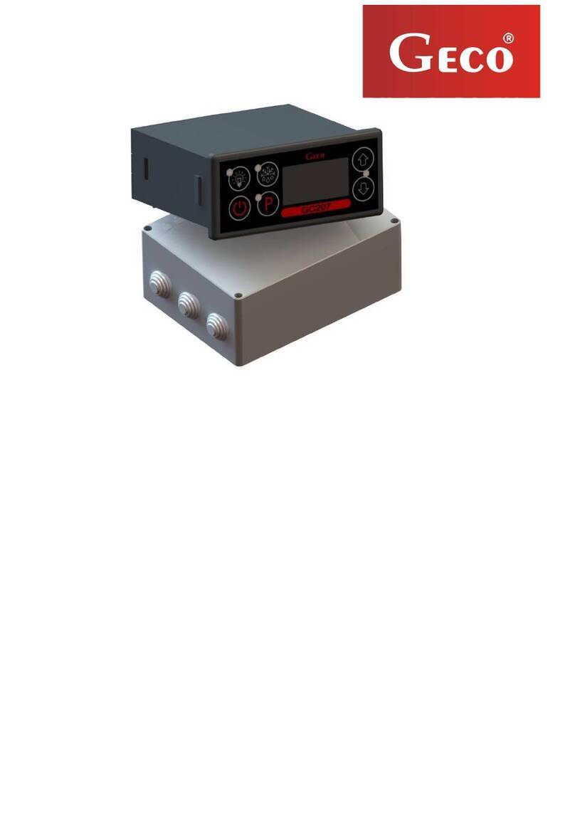
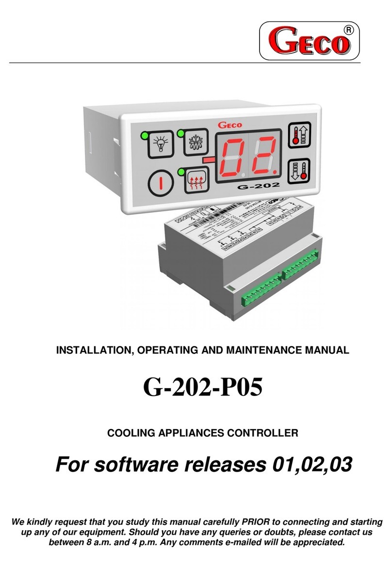
The Standalone Control Block (SBR) GC202 is a modern, convenient and easy to use device. The
Controller is a microprocessor-based device manufactured using Surface Mount Technology (SMT).
Thanks to the two-piece housing, the GC202 can be used for any piece of furniture and a simple cold
room. Operating under a safe 12V voltage, the control panel can be mounted anywhere, without need
for cutting additional holes and guiding many power-supply cables far from the controlled appliances.
GC202 is able to work with two temperature sensors as standard and, depending on the
configuration of the parameter, a third temperature sensor or a door opening (magnetic or optical)
sensor can be connected to the controller. All sensors are connected to the executive module and they
work under a safe 12V voltage. The controller module also has four outputs enabling direct connection
of devices operating at 230V with the load capacity as in Table 1.
As standard, the controller is equipped with sound signalling which is activated when any button on
the keypad is pressed and when an alarm goes off.
In order to provide the user with the comfort while using the controller, capacitive (touch) buttons
have been used in the keypad.
GC202 stabilises the temperature and controls automatic defrosting, the period of which can be
adjusted to specific environmental conditions. It also has a button for manual defrosting of the
evaporator.
The controller panel is additionally equipped with a lighting button (depending on the keypad
version) operating independently of the main switch.
This thermostat does not require any special maintenance; the keypad is made of plexiglass
resistant to high temperatures and most chemicals. It is not permitted to clean it with sharp objects. It
suffices to wipe the panel front with a damp cloth from time to time.
II. MARKING AND SPECIFICATIONS
Model designation: GC202.0X
0X –number denoting the controller version
01 –3-relay controller controlling the following devices:
compressor/fan/heater or valve.
The keypad of the controller panel is made without the light button.
The standard DD input allows the connection of an additional sensor, the selection of which
depends on the r6 parameter. Depending on the setting of this parameter, we can connect a
door opening (mechanical or magnetic) sensor or an additional temperature sensor acting as
a thermometer (for r6=3).
02 –4-relay controller controlling the following devices:
compressor/light/fan/heater or valve.
The keypad of the controller panel is made with a light button.
The standard DD input allows the connection of an additional sensor, the selection of which
depends on the r6 parameter. Depending on the setting of this parameter, we can connect a
door opening (mechanical or magnetic) sensor or an additional temperature sensor acting as
a thermometer (for r6=3).

Page 4
2nd edition
AS FROM 20.04.2022
03 –4-relay controller controlling the following devices:
compressor/light/fan/heater or valve.
Controller panel keypad made with light button.
The standard mounted input 1-2-3 allows the connection of an additional sensor, the
selection of which depends on the r6 parameter. Depending on the setting of this parameter,
we can connect an optical door opening sensor or an additional temperature sensor acting as
a thermometer (for r6=3).
Operating voltage
230V +10% -15%
Operating temperatures
+5ºC to +40ºC
Relative humidity
20% to 80% RH
Ingress protection
IP65 at the front of the control panel
Type of temperature
sensors
NTC 2,2kΩ –measurement range: -400C to
+600C
Table 1: Designation of relays and output loads
EXIT
RELAY
RECOMMENDED MAXIMUM CONTINUOUS LOAD
P1 –Compressor
30A
8A
2HP
1500W
P2 –Light
8A
4A
-
750W
P3 –Fan
16A
4A
1HP
750W
P4 –Heater / Valve
8A
8A
-
1500W
Attention!!!
Currents given in the table are the currents consumed by individual devices
during normal operation and include the starting currents of these devices!!!
The total current consumed simultaneously by the devices must not
exceed 10A!!!
III. ORDERING INFORMATION
The order should specify:
1. Full name of the controller, e.g. GC202.02
2. Length of the ribbon connecting the executive module and the keypad panel (the standard
length of the ribbon is 1m).
3. Length of temperature sensors (standard sensor lengths are 2.5m and 3.0m).
4. Length of the cable to the door opening sensor (standard: to the reed switch 2.0m; to optical
sensor 2.5m).
5. Type of fully contactless door opening sensor:

Page 5
2nd edition
AS FROM 20.04.2022
magnetic sensor with range of 1-2cm,
optical sensor with a range of 1-2cm.
IV. DELIVERY, INSTALLATION AND CONNECTION
1. Cut a hole measuring 20x30mm in the designated place in the device, and if the panel masking is
not used, the hole should be 58x109mm.
2. The executive module should be placed on the rail and locked with a latch.
In the case of shop devices, it is REQUIRED to mount the SBR executive module with the
mounting strip facing down!!!
3. Any metal elements through which the GC202 or its cables are passed should be filed down or
otherwise secured. It is not permitted to mount the GC202 allowing the direct impact of water
on it (e.g. water condensing on the lower cover of the display case), touching the evaporator
drain pipe, etc. and causing significant changes in its temperature in relation to the ambient
temperature (e.g. mounting in the immediate vicinity of the compressor and its accessories,
cooled and heated elements).
4. Cut the ribbon connecting the panel with the executive module to the desired length plus 2-3cm.
Then, after putting it through all the passages, cut its ends again at a right angle and clamp the
plugs on it so that the end of the ribbon is hidden inside them for about 0.5mm. The ribbon must
be introduced perpendicularly to the plug and tightened without the possibility of any twisting or
non-parallel arrangement. For connecting the ribbon to the connectors see Fig. 3.
5. After mounting the GC202, connect the power cables in accordance with the description on the
module nameplate. Depending on the GC202 version, some outputs may be unused –an X will
be inserted in their place –no wires must be connected to these outputs!!!
6. The connectors used are certified for a continuous load of 16A!!! They use a fine-pitch thread
and special plates to prevent cutting wires, so even a slight tightening results in maximum good
contact, and the use of greater force can lead to thread breakage. As a result, the socket may
melt and a short-circuit may occur!!!
7. All cable surpluses are shortened by cutting or rolling and fastening them with special plastic ties.
The cables must be securely fastened along their entire length and must not touch the
compressor and its accessories.
8. After connecting the device to the power supply, there may be voltage on the lighting cable,
regardless of switching the device on or off with the button, therefore the starter or
fluorescent lamp can be replaced only with the power cord disconnected from the socket!!!
THE SAME CONDITION APPLIES TO ANY OTHER REPAIRS!!!
9. If heaters are used, their power must be selected so that in the event of a failure of the GC202 or
the contactor and switching them on permanently, there is no possibility of fire or destruction of
the device. If high-power heaters are used, it is absolutely necessary to use a safety thermostat
on the evaporator; this thermostat should operate differently, e.g. a mechanical thermostat.

Page 6
2nd edition
AS FROM 20.04.2022
V. INSTALLATION OF SENSORS, TYPES OF COVER SHELLS
1. For each type of manufactured device, the place of mounting the chamber and evaporator sensor,
as well as the SBR setting should be selected experimentally. It is absolutely forbidden to change
the place or method of mounting the sensors and SBR settings without conducting new tests
regarding temperature stabilisation and defrosting of the device!!!
2. The chamber sensor must be attached in such a way that it does not touch the food and is not
exposed to damage while cleaning the device. A special plastic holder can be used to attach this
sensor. This solution causes a quick reaction in the sensor (time delays on/off, see VI p.5) and the
entire thermostat to the change of air temperature in the device. If it is advisable or necessary to
slow down and “smooth” the reaction time of the sensor to temperature changes, we suggest
screwing it to a metal element of the device.
3. The evaporator sensor should be mounted in a way that ensures maximum solid and reliable
contact with the evaporator lamella and in such a place where the ice stays the longest during
defrosting. Its attachment should prevent it from being pushed out by accreting ice. Sensors should
be mounted vertically, if possible, with the cable coming out at the bottom of the sensor.
4. The sensor cables can be shortened or extended in any way, however, observing the following
rules:
-
do not cut the sensor cable at a distance of less than 0.5m from the shell
-
it is not recommended to extend the sensor cable beyond 20m.
-
THE WAY OF CONNECTING THE SENSOR CABLES TO THE SENSOR TERMINALS OF THE ACTUATOR
MODULE IS FREE!!! (similar to the method of inserting the plug into the ~230V socket)
-
to extend the cables, we suggest using an OMY 2x0.5mm cable
-
connection of the cables in the case of extensions should be done very carefully, each of the
pairs of wires is soldered and heat-shrinkable sleeves are put on them. Then, the connection
point should be flooded with waterproof silicone and another heat-shrinkable sleeve should be
clamped on it.
-
ends of the wires connected to S.B.R. should be tinned.
VI. GENERAL OPERATION PRINCIPLES
A –General information
1. Start after power on
After connecting the device to the power supply, a 3-second starting procedure is performed,
during which three dots will light up on the display for one second, the controller program version
for another second, and three dots again. During this time, none of the controlled devices is
switched on.
If the device was turned on before a power failure, after the start-up procedure is completed,
the device is turned on and the temperature value appears on the display. If an additional
temperature sensor is connected, its indication will appear on the display. It does not affect the
operation of the device, but only serves as an electronic thermometer. In the absence of this third
sensor, the temperature value from the chamber sensor is displayed.
If the device was switched off, it remains switched off and three horizontal lines appear on the
display. It is turned on after pressing and holding the button for 5 seconds.

Page 7
2nd edition
AS FROM 20.04.2022
2. Button functions
–Pressing and holding for 5s turns the controller on/off. As the button is held down, an
ascending beep is generated. The off state is signalled by three horizontal lines on the display.
Pressing turns the lighting on or off. This is signalled by a green LED next to the button.
The button works independently of the thermostat switch –.
This is used to activate defrosting manually.
- This is used to enable setting programming and to end programming.
- This is used to increase the set temperature during programming and to enable the evaporator
temperature preview. To enable the evaporator temperature preview, hold the button longer, then
the display will start flashing and indicate the reading. After 5 seconds, the GC202 will automatically
return to reading the temperature of the chamber or the additional temperature sensor.
Attention!!! The preview is also active during defrosting, when 'dF' is lit on the display.
- This is used to reduce the set temperature during programming and to enable the preview of
the chamber temperature when working with an additional temperature sensor, as well as during
defrosting, when 'dF' is lit on the display. By briefly holding the button, the display will start showing
(without blinking) the temperature of the chamber, and after 5 seconds GC202 will automatically
return to displaying 'dF'.
3. Temperature setting programming
After pressing the button, programming mode is entered, the display shows the setting value
and the LED next to the button lights up.
Pressing or changes the setting value in the range of 'd0' to 'd1'.
Pressing saves the settings and the controller returns to normal operation.
If the GC202 is turned off during programming, it will not remember the new temperature
setting!!!
4. Compressor operation indication
Compressor activation is indicated by lighting of a small red diode (dot) in the lower right corner
of the temperature display. This allows easier checking of possible system malfunctions.
Should the compressor be switched on, but it is not due to the activation of one of the
protections (see point 5), the dot indicating the compressor operation will blink. After the set
protection time has elapsed, the dot will light up permanently and the compressor will be turned on.
5. Compressor protection
The delay in switching on the compressor after reaching its activation temperature (temperature
set by the user minus the lower hysteresis value) is 30 seconds. If the temperature drops during this
time, the 30 second condition will be checked again.

Page 8
2nd edition
AS FROM 20.04.2022
This is to protect the compressor from unnecessary activation, for example caused by putting goods
in, draughts, etc.
Every time the temperature setting is reached (the user temperature setting plus the upper
hysteresis value) and after every power outage or drop below 175V, the GC202 allows the
compressor to be re-activated for the time determined by the 'c02' parameter. However, if
'c02'=0min., the compressor starts after 30 seconds.
After switching on the device with the button, there is a 5-second delay in switching on the
compressor. Please note that this will cancel all other protections, including the time set by 'c02' after
the compressor has been turned off before. This allows quicker checking of the compressor
operation.
6. Sensor alarms –A1, A2 and A3
The Controller is equipped with alarms indicating sensor failures. The behaviour of the controller
will be different depending on which sensor has been damaged.
Damage to the sensor is signalled by the appearance of a relevant message on the display along with
a beep. After pressing any button, the alarm signal is silenced.
If the A1 alarm occurs, it is displayed instead of the chamber temperature or the temperature from
the additional sensor. In the case of the A2 alarm, the message is displayed alternately with the
temperature in the chamber or with the temperature from the additional sensor. When the A3 alarm
is activated, it is displayed alternately with the chamber temperature. If the three sensors fail
simultaneously, the alarm messages are displayed alternately. The same happens when there are
two alarms in the configuration: A1 and A3 and A1 and A2. When there is a failure from the
evaporator probe and the additional temperature probe, the A2 and A3 alarms are displayed
alternately along with the temperature of the chamber.
A1 –Damage to the chamber temperature sensor. GC202 will turn on the compressor in a time cycle
(so-called timer control) according to the times specified in the 'c08' and 'c09’ parameters.
Defrosting will operate normally.
A2 –Damage to the evaporator sensor. Manual and automatic defrosting operation is blocked!!!
The only way to defrost the device is to turn it off with the button and wait for the ice to melt
naturally.
A3 –Damage to the additional temperature sensor. If the parameter is r6 = 03, the sensor damage
alarm will be signalled. If we change the parameter to r6 = 00, then the function of the third sensor
(also the door opening sensor) will be disabled and the controller will not report an alarm.
7. Fan control based on evaporator temperature
If the 'd6' parameter is set to a value lower than 40ºC, the controller shuts down the fan when the
evaporator temperature is higher than the 'd6' parameter value. This function is not available in the
defrosting mode.
B –Defrosting
1. If additional defrosting is required due to difficult working conditions, press the button. The
green LED on the button will then be on continuously and the display will show 'dF' instead of
the temperature measurement, at which point the device will enter the defrosting cycle.
2. If the 'c00' time has elapsed since the last defrosting activation and the compressor is running at
this moment, the automatic defrost activation will be delayed until the compressor is deactivated as
a result of reaching the set temperature or exceeding the maximum operating time specified in the
'c05' parameter.

Page 9
2nd edition
AS FROM 20.04.2022
3. If defrosting takes place and the temperature on the evaporator is higher than the value set in the
'd2' parameter, the device will enter the defrosting exit phase after about 10 seconds and once
completed, it will resume operating.
4. If defrosting occurs and the temperature on the evaporator is lower than the value set in the 'd2'
parameter, the GC202 will start defrosting and after reaching the temperature specified in the 'd2'
parameter, it will enter the defrosting exit procedure (this state is signalled by the blinking of the
green diode on the button), in the version with heaters, the defrosting exit procedure is
performed, consisting of two successive phases:
dripping phase –in which the compressor and evaporator fans are off for the time set by the
'c03' parameter
evaporator freezing phase –in which only the compressor operates in order to lower the
evaporator temperature to the temperature defined by the 'd5' parameter before restarting
the fans. The maximum and non-extendable freezing time, regardless of the evaporator
reaching the 'd5' temperature, is defined by the 'c04' parameter.
5. The procedure of exiting the defrosting is completed by starting the fans, turning off 'dF' on the
display and switching off the blinking of the green LED on the button.
6. In the absence or non-connection to S.B.R. fans, the system will behave as if they were installed.
7. Defrosting will be completed after reaching the temperature set in the 'd2' parameter on the
evaporator or after exceeding the time set in the 'c01' parameter.
8. After switching off 'dF' and the end of defrosting, the display will show the temperature stored just
before the start of defrosting for the time specified in the 'c07' parameter –this is to prevent
complaints due to “rapid temperature jumps in the device”'.
9. The system behaves in the same manner for manual and automatic defrosting.
10. The 'r0' parameter allows forcing the fan into the switch-on mode during defrosting.
11. The fan cannot be adjusted using the 'd6' parameter during defrosting.
C –Door opening sensor operating principle
1. If the door is opened, the fan stops immediately and in GC202, depending on the setting of the 'r7'
parameter, the light may be turned on. The temperature reading is shown in the display. If the
opening of the door is a cause of the light being switched on, the diode next to the button does
not light up.
2. The door opening sensor can also switch on the light when the controller is off (three horizontal
lines on the display). The word 'dr' will then be displayed without a beep.
3. After 30 seconds, if the door has not been closed, the word 'dr' is displayed continuously on the
display. There is a short beep that is repeated every 30 seconds.
4. If the door has still not been closed after the time specified in the 'r8' parameter, the alarm is
activated, signalled by the flashing of the display with the word 'dr' and a beep. At the same time
the compressor is switched off.
5. If, after opening the door, r8 = 0 the alarm is immediately activated.
6. You can cancel the alarm by pressing any key. Closing the door deactivates the alarm and restores
normal operation.
7. The controller allows the connection of a mechanical, magnetic and optical door opening sensor,
depending on the version of the controller.

Page 10
2nd edition
AS FROM 20.04.2022
If the parameter is r6=01, the sensor is closed when the door is opened, while if the parameter is
r6=02, the sensor is open when the door is opened.
D –HYSTERESIS
When programming the 'd0' and 'd1' parameters (the minimum and maximum temperature that can be
set by the customer), remember that the 'd3' hysteresis value causes an additional 'pull' of the
temperature down and up from the temperature set by the user.
This is of particular importance in the case of devices 'plus', which should always work above 0ºC.
Example:
As a manufacturer of a cooling appliance, in this case a cooling counter (positive temperatures), we
require that the device enabled operation be only within the range of temperatures that do not exceed
the below specified values: Switch off min.: 2ºC. Switch on max.: 10ºC
Symmetrical hysteresis for even values of 'd3'
Symmetric hysteresis for odd values of 'd3'
Example 1.
For example, the 'd3' hysteresis is set to: 2ºC.
For the above hysteresis setting you should also
set the parameters:
'd0' at 3ºC and 'd1' at 9ºC
Example 3.
For example, the 'd3' hysteresis is set to: 3ºC.
For the above hysteresis setting you should also
set the parameters:
'd0' at 3ºC and 'd1' at 8ºC
Example 2.
For example, the 'd3' hysteresis is set to: 4ºC.
For the above hysteresis setting you should also
set the parameters:
'd0' at 4ºC and 'd1'at 8ºC
Example 4.
For example, the 'd3' hysteresis is set to: 5ºC.
For the above hysteresis setting you should also
set the parameters:
'd0' at 4ºC and 'd1‘ at 7ºC
Fig. 1. Hysteresis principle of operation.
VII. ON/OFF DIAGRAMS FOR INDIVIDUAL ASSEMBLIES OF THE
APPLIANCE
A bold line means turning on, and a thin line turning off individual devices. Defrosting exit consists of
two phases –see chapter VI p. B-Defrosting.
The “Downtime” field means switching off, and “Work” –switching on of the compressor due to
exceeding the programmed temperature, of course, taking into account the value of the programmed
hysteresis, parameter 'd3'.
Switch off temp.
Temp. set by the
user
Switch on temp.

Page 11
2nd edition
AS FROM 20.04.2022
The heater on “diagram 1” is for heating the tray and/or the evaporator water drain hose, and the heater on
“diagram 5” is for heating the evaporator water drain hose only.
ERROR IN PARAMETERS SETTING WILL RESULT IN WRONG OPERATION OF THE
DEVICE!!!
The first 6 graphs refer to setting the parameter 'r0' = 00 –the fan is switched on during defrosting.
1. Defrosting by compressor stoppage 'r1'=01, fans run only together with compressor 'r2'=00,
COMPRESSOR
TRAY HEATER
FAN
Stop
Work
DEFROSTING
EXIT DEFROSTING
Work
Stop
t=0 (c3 and c4 irrelevant)
2. Heater defrosting 'r1'=02, fans run only together with the compressor 'r2'=00
COMPRESSOR
HEATER
FAN
Stop
Work
DEFROSTING
EXIT DEFROSTING
Work
Stop
3. Warm vapour defrosting 'r1'=03, fans run only together with the compressor
'r2'=00
COMPRESSOR
VALVE
FAN
Stop
Work
DEFROSTING
EXIT DEFROSTING
Work
Stop
4. Warm vapour defrosting 'r1'=03, fans run all the time when the device is on 'r2'=01
COMPRESSOR
VALVE
FAN
Stop
Work
DEFROSTING
EXIT DEFROSTING
Work
Stop
5. Defrosting by compressor stoppage 'r1'=01, fans run all the time when the device is on 'r2'=01
t=0 (c3 and c4 irrelevant)
COMPRESSOR
DRAIN HEATER
FAN
Sto
p
Work
DEFROSTING
EXIT DEFROSTING
Work
Stop
6. Heater defrosting 'r1'=02, fans run all the time when the device is turned on 'r2'=01
COMPRESSOR
HEATER
FAN
Stop
Work
DEFROSTING
EXIT DEFROSTING
Work
Stop

Page 12
2nd edition
AS FROM 20.04.2022
The graphs below refer to the 'r0'=01 parameter.
VIII. SETTING THE SYSTEM PARAMETERS
Once the device is started and checked for proper operation (default settings are factory set) you
can begin to enter the system parameters of the GC202.
To do this, turn off the device with the button (three horizontal lines will appear on the
display). Then press the and and and while holding them press the button (a short beep
will be activated). Keep all three buttons pressed together for approx. 5 seconds. Releasing any of the
keys during that period will cause exiting the programming mode. After
After doing this, the LEDs on the and buttons should start flashing and the display will show 'c0' for
one second. Then the previously set value for the parameter will be shown. Now use and to
enter the required settings; each longer holding
the button will cause fast “scrolling” of the indications. Then press to accept the entered data and
move on to entering the next parameter.
It is possible to introduce partial settings, if you do not want to change a given setting, press
and GC202 will go to the next parameter.
After entering the setting of the last parameter and accepting it with the button, the
programming mode will be automatically exited and the STANDBY mode will return (three horizontal
lines on the display).
7. Heater defrosting 'r1'=02, fans run only with the compressor 'r2'=00, a fan is on during defrosting
'r0'=01
COMPRESSOR
HEATER
FAN
8. Warm vapour defrosting 'r1'=03, fans run all the time when the device is turned on 'r2'=01, a fan is on
during defrosting 'r0'=01
COMPRESSOR
VALVE
FAN
9. Warm vapour defrosting 'r1'=03, fans are on only with the compressor 'r2'=00, a fan is on during
defrosting 'r0'=01
COMPRESSOR
VALVE
FAN
10. Heater defrosting 'r1'=02, fans run all the time when the device is turned on 'r2'=01, a fan is on during
defrosting 'r0'=01
COMPRESSOR
HEATER
FAN
Stop
Work
DEFROSTING
EXIT
DEFROSTING
Work
Stop
Stop
Work
EXIT DEFROSTING
DEFROSTING
Work
Stop
Stop
Work
DEFROSTING
EXIT DEFROSTING
Work
Stop
Stop
Work
DEFROSTING
EXIT DEFROSTING
Work
Stop

Page 13
2nd edition
AS FROM 20.04.2022
If no button is pressed within 20 seconds, the device will exit the parameter programming mode.
ATTENTION !!!
Incorrect change of parameter settings may cause faulty operation of the
device!!!
Table 2: Designation of parameters
Para
met
er
Des
cript
ion
Min.
Max
.
Step
Factory
setting
C00
How often defrosting should take place Attention!!! If this
parameter is set to “0”, there will be no automatic defrosting, only
manual defrosting!!! If this parameter is set to “-01”, there will be
no automatic or manual defrosting!!!
-01
24
1h
6h
C01
Maximum defrosting time if the evaporator does not reach the set
temperature (parameter d2) Attention!!! If this parameter is set to
“-01”, there will be no time limit
-01
99
1min
30min
C02
Minimum compressor downtime duration
0
15
1min
3min
C03
Evaporator dripping duration
0
15
1min
2min
C04
Evaporator freezing time, after which the fans will start, regardless
of whether the evaporator reaches the temperature set in the 'd5'
parameter
1
25
1min
10min
C05
Maximum compressor operation duration
0 –means there is no test (the parameter is disabled)
0
99
1min
40min
C06
Compressor downtime duration after activation of protection set in
parameter 'c5'
0
99
1min
10min
C07
The time during which, after the end of defrosting ('c4' parameter),
the temperature measured just before the start of defrosting will
be displayed.
0
60
1min
5min
C08
Compressor operation time when the control sensor is damaged
1
99
1min
25min
C09
Compressor downtime when the control sensor is damaged
1
60
1min
5min
d0
Minimum temperature that can be set by the customer
-40
20
1°C
1°C
d1
Maximum temperature that the customer will be able to set
d0+1
40
1°C
10°C
d2
Evaporator temperature at which the defrosting is finished
0
40
1°C
5°C
d3
Hysteresis value
1
10
0.1°C
2°C
d4
Value of the chamber sensor re-scaling from the actually measured
temperature
-10
10
0.1°C
0°C
d5
Evaporator temperature at which the fans will start after
defrosting
-30
10
1°C
-5°C
d6
Evaporator temperature above which the fan is always off.
Setting the parameter to +40°C disables this control.
-40
40
1°C
5°C

Page 14
2nd edition
AS FROM 20.04.2022
r0
Mode of fan operation during defrosting
00 –works according to the diagrams in chapter VII
01 –always on during defrosting
02 –always off during defrosting
00
02
1
00
r1
Determining the defrosting method of the evaporator, the
parameter is set to:
01 –defrosting by compressor stoppage
02 –heater defrosting
03 –warm vapour defrosting valve (reverse circuit)
01
03
1
02
r2
Determining the mode of operation of the evaporator fans, the
parameter is set to:
00 –fans work only together with the compressor
01 –fans run all the time after power on
ATTENTION!!! This parameter has no effect on the evaporator
defrosting cycle and method
00
01
1
01
r3
Determination of the temperature control method, parameter set
to:
00 –normal regulation
01 –the temperature is adjusted according to the measurement
from the evaporator sensor, the programmed temperature and
d0, d1, d2 and d3 parameters apply to the evaporator sensor, the
measurement from the chamber sensor is displayed.
00
01
1
00
r5
Conditions for defrosting activation during the device start:
00 –start of operation without defrosting
01 –if a power outage occurred during defrosting, defrosting is
activated
02 –defrosting after each switching the device on.
00
02
1
00
r6
Optional door opening sensor or additional temperature sensor.
00 –no door opening sensor
01 –door opening sensor exists, closed when the door is open
02 –door opening sensor exists, open when the door is open
03 –there is a temperature sensor (thermometer)
00
02
1
01
r7
Lighting activation methods:
01 –light controlled only by the door sensor
02 –light controlled only by the keyboard
03 –light controlled by both the door sensor and the keyboard
01
03
1
03
r8
Time elapsed after door opening until alarm activation.
30 seconds after opening the door, the word 'dr' is displayed and a
short beep is heard, which is repeated every 30 seconds.
After the r8 time elapses, the alarm is activated, signalled by the
flashing of the display with the word 'dr' and a beep, and the
compressor is turned off.
0 –means immediate alarm activation
00
20
1min
1min

Page 15
2nd edition
AS FROM 20.04.2022
IX. TROUBLESHOOTING
Symptoms
Checks
1. The display does not
light up even though
the GC202 is
connected to the mains
- the presence of 230V voltage on the L and N power terminals
- correct connection of the executive module with the control panel
- pull out and insert the ribbon slots
- connect another ribbon
2. The compressor does
not turn on despite
signalling its activation –
red diode
- presence of 230V voltage on terminals K and N –If present, check
the compressor
- if not, check the correct connection of the executive module with the
control panel
- connect another ribbon
3. The defrosting heater
does not turn on
- presence of 230V voltage on terminals according to the description
on the top side of the executive module
- if it is, check the heater
- if not, check the correct connection of the executive module with the
control panel
- connect another ribbon
4. The light tube does
not go on
- presence of 230V voltage on terminals according to the description
on the top side of the executive module
- if it is, check a/ starter, b/ fluorescent lamp, c/ choke or other lighting
elements
- if not, check the correct connection of the executive module with the
control panel
- connect another ribbon
5. Incorrect temperature
reading
- connecting sensors to connectors
- 'd4' parameter value
- correct mounting of the sensor
- condition of the sensor cable –the cable must not have any damage
- Check the exact appearance of the outer surface of the sensor shell to
see if it has not been mechanically damaged.
6. It is not possible to set
the desired temperature
value of 'd0' and 'd1' parameters (d0<d1)
7. Flashing dots on
display, no switching on
possible
- supply voltage value
- condition of power connectors
- tightening the power connectors
- correct connection of the executive module with the control panel
- connect another ribbon
8. ‘Abnormal’, ‘strange’
behaviour of the device
- the presence of 230V voltage on the L and N power terminals
- condition of power connectors
- zeroing of the refrigeration unit
- condition of the electrical installation and the number of devices connected
to one phase
- do you have the correct type of a thermostat (output label) for your
device?
- have the control panel, actuator module or ribbon plugs not been
exposed to water or other liquid
- are the control panel, module or ribbon plugs not exposed to moisture or
rapid temperature changes

Page 16
2nd edition
AS FROM 20.04.2022
- correct connection of the executive module with the control panel
- connect another ribbon
9. Problems with
appliance defrosting
- 'd2' and 'c00', 'c01' parameter value
- 'c01' parameter value This is the maximum defrosting time of the
device, regardless of whether the evaporator has reached the
programmed defrosting end temperature or not ('d2' parameter). If this
duration is too short, the appliance will not be able to defrost completely.
- correct mounting of the sensor to the lamellas of the evaporator.
IT MUST BE FIRMLY MOUNTED AND TIGHTLY ADHERE TO THE
LAMELLAS!!!
- if the evaporator sensor is mounted in the place where the ice stays the
longest, if not, check the temperature on the sensor when the last ice
nuggets fall from the evaporator. THIS TEMPERATURE SHOULD BE
ENTERED THEN AS 'd2' PARAMETER
10. The appliance does
not reach its set
temperature and its
cooling function is not
working
- what temperature has been programmed by the user
- values of specific parameters, especially the 'c02', 'c05', 'd0', 'd1'
- point 9 –Problems with defrosting the device. If the appliance does
not defrost completely, it will not reach its set temperature!!!
- method and place of attaching the chamber sensor
- have the side windows in the rack and the sliding windows in the
display case not been dismantled
- MAKE SURE THE DEVICE IS NOT POSITIONED IN A DRAUGHT OR IN
THE SUN!!!
- are there no fans or air conditioning installed on or near the ceiling
- condenser cleanliness
- temperature in the store (each manufacturer provides max. operating
temperature for the appliance)
- amount of gas, fans, evaporator heater, evaporator drain hose
11. Incorrect operation of
the door opening sensor
- 'r6' and 'r7' parameter value
- correct sensor connection
- check the correct connection of the executive module with the
control panel
- connect another ribbon
X. RETURNING FOR REPAIR
PPUH GECO reserves the right to refuse to accept the device for free
repair if the seals are found to be broken!!!
P.P.U.H. Geco Sp. z o.o. is not liable for losses and damage resulting from
the fact that the manufacturer of the refrigeration device or its service
provided the final customer with information on how to make changes to
the GC202 system data, incorrect or unprofessional installation, and for
losses caused by malfunction of the device.

Page 17
2nd edition
AS FROM 20.04.2022
XI. DIAGRAM OF CONNECTION OF DEVICES TO THE CONTROLLER
Fig. 2 Scheme of connecting devices to the main controller module.
THE PICTURE SHOWS A VIEW OF THE PLUGS
FROM THE SIDE OF THE HOLES AND THEIR
RELATION TO EACH OTHER AND THE
SELECTED RIBBON STRIP, AFTER THE
CORRECT CONNECTION!!!
Fig. 3 View of the ribbon after proper connection.
Power supply
1* –version with a mechanical door opening
sensor: GC202.01, GC202.02
2* –version with optical door opening sensor:
GC202.03
Door sensor:
1 –OUT –black
2 –GND –blue (previously white)
3 –+12V –brown (previously red)
TEMPERATURE SENSORS
DOOR SENSOR
OPTICAL SENSOR
TEMPERATURE SENSORS
Ribbon
Connector
Manufacture Date:
Model:
Ns.
CONTROL
P1 –Light
P2 –Fan
P3 –Heater
P4 –Compressor
P-P EVAPORATOR sensor –GRAY
K-K CHAMBER sensor –WHITE
D-D Door Open Sensor
TEMPERATURE SENSORS
DOOR SENSOR
K-K CHAMBER sensor
P-P EVAPORATOR sensor
D-D Door Open Sensor

Page 18
2nd edition
AS FROM 20.04.2022
XII. INFORMATION ON MARKING AND COLLECTING WASTE
ELECTRICAL AND ELECTRONIC EQUIPMENT
ATTENTION!
The symbol placed on a product or on its packaging indicates that it is
subject to selective collection of waste electric and electronic
equipment. This means that the product should not be discarded with
other household waste. Appropriate removal of old and waste
electric and electronic equipment will prevent potentially harmful
effects on the environment and human health.
The obligation of selective equipment collection rests on the user who
should deliver the equipment to a collection point.
Table of contents
Other Geco Controllers manuals