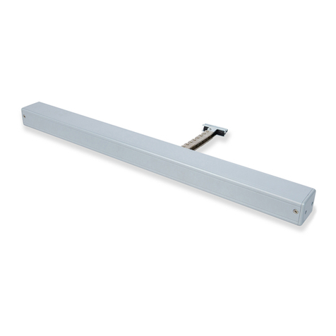
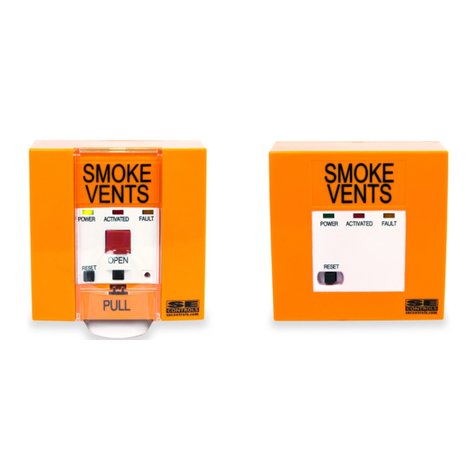
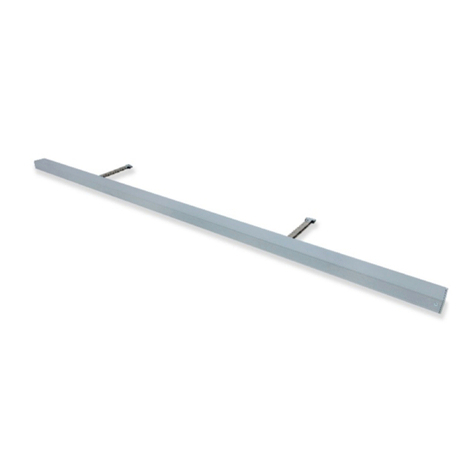
SE Controls SECO Ni Manual

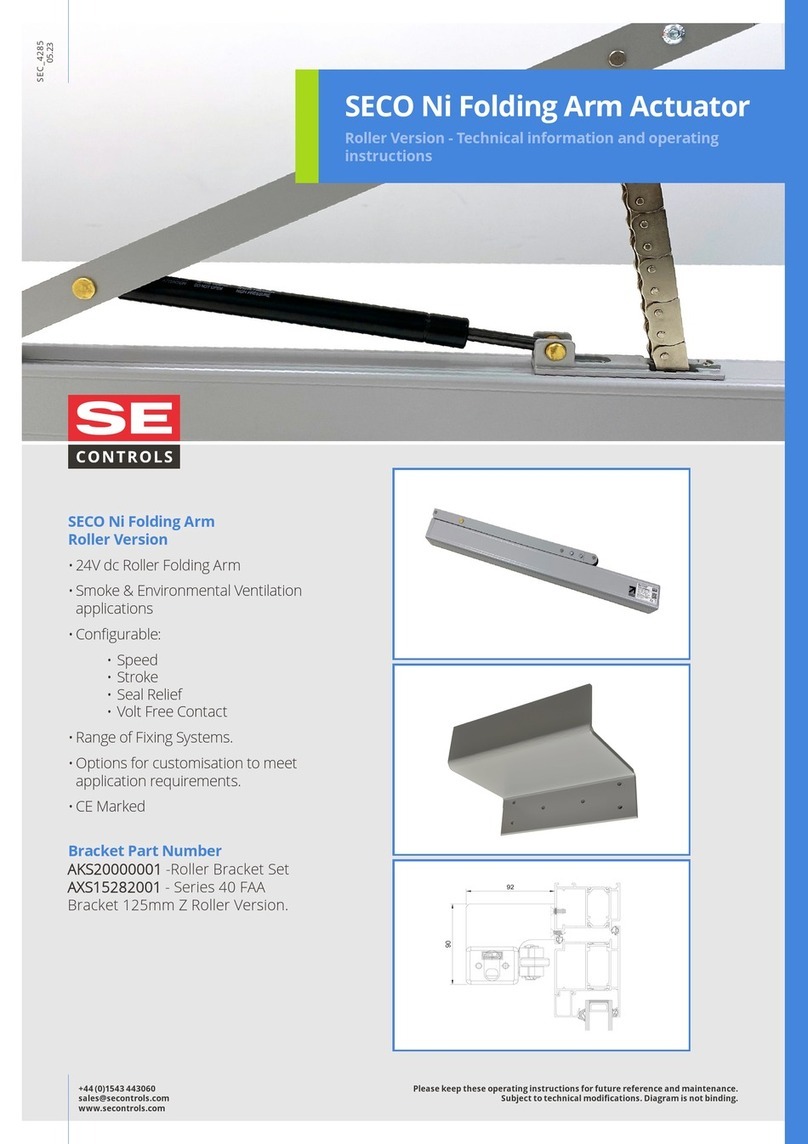
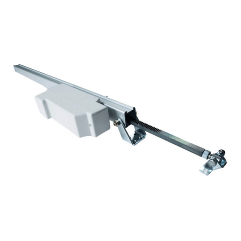
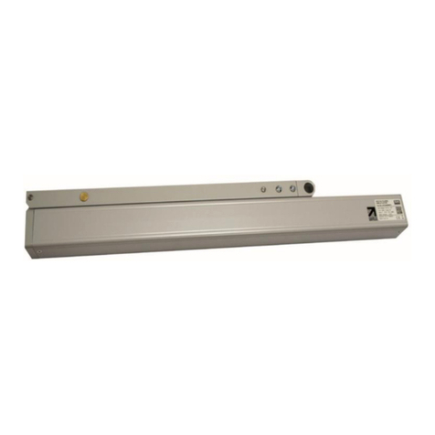
SECO Ni Folding Arm Actuator
Roller Version - Technical information and operating
instructions
SEC_4285
11. 20
+44 (0)1543 443060
sales@secontrols.com
www.secontrols.com
Please keep these operating instructions for future reference and maintenance.
Subject to technical modifi cations. Diagram is not binding.
SECO Ni Folding Arm
Roller Version
• 24V dc Roller Folding Arm
• Smoke & Environmental Ventilation
applications
• Confi gurable:
• Speed
• Stroke
• Seal Relief
• Volt Free Contact
• Range of Fixing Systems.
• Options for customisation to meet
application requirements.
• CE Marked
Bracket Part Number
AKS20000001

+44 (0)1543 443060
sales@secontrols.com
www.secontrols.com
Please keep these operating instructions for future reference and maintenance.
Subject to technical modifi cations. Diagram is not binding.
Specifi cation
Actuator SECO Ni Folding Arm Actuator
Actuator Type 24V dc Folding Arm Actuator
Amp Draw Current (with load) 1.0A
Stroke 90°
Operating Speed 15mm/sec
Ambient Operating Temp -5°C +60°C
Thrust Force 400N
Close Force 400N
Soft Close Yes
Switching Electronic
Standard Finish Grey (RAL 9006)
Seal Relief Programmable up to 20mm
Clamping Force 4000N
Colour Option Other RAL colours available on request
Flex Length 2m
Flex Type 5 Core - 2x 0.75mm ² / 3x 0.25mm ²
Flex Colour Grey
Product Warranty 15,000 cycles
Duty Cycle 22% (2 mins on, 7 mins off )
Protection Degree IP20
Bracket Frame Mounted Roller
Synchronisation Optional
Application Smoke and Environmental Ventilation

+44 (0)1543 443060
sales@secontrols.com
www.secontrols.com
Please keep these operating instructions for future reference and maintenance.
Subject to technical modifi cations. Diagram is not binding.
1.1 General Safety Information
SE Controls reserves the right to introduce any
modifi cations and improvements to the contents of this
publication without the obligation of giving prior notice.
Read and observe the information contained in these
safety instructions and respect the order of procedure
stated therein.
Please keep these safety instructions for future reference
and maintenance. Reliable operation and the prevention
of damage and risks are only granted if the equipment
is assembled carefully and the settings are carried out
according to these instructions and to the operating
instructions of the drives.
Please observe the exact terminal assignment, the
minimum and maximum power ratings (see technical data)
and the installation instructions.
Please observe the following warning symbols:
1.2 Health and Safety
Warning!
Carefully ready these warnings
Warning!
Danger of electric shock.
Warning!
Draws attention to instructions that must
be followed in order to prevent damage to
the actuator.
Notice
Indicates important notices to which
attention must be paid.
All actuator products contain metallic, plastic
and electronic parts. Redundant electronic
products are classifi ed as hazardous waste
under the WEEE regulations (Waste Electrical
and Electronic Equipment). Electronic parts
must be disposed by an authorised and
licensed recycler.
Handling and storage; Care must be taken in transportation
to the installation location and during fi tting. Actuator
products must not be dropped, impacted, allowed to get
wet or abused in any other way. Mishandling can result in
serious damage.
Competence; Installation and connection must only be
carried out by authorised, competent and safety conscious
persons.
1.3 Environmental
They must not be disposed of in ‘general waste’ skips.
Consult SE Controls for assistance.
Danger!
General danger or precautionary warning
with numerous implications.
Danger!
Danger that could cause personal injury.
Danger of hands been crushed!
Electrical Safety; Warning 230 V AC Dangerous
voltage. Can cause death, serious injury or
considerable material damage. Disconnect the
equipment from the power supply at all poles
before opening, assembling or carrying out any
structural alterations.
Warning! Never connect the drives to 230V!
They are built for 24V! Risk of death!
Personal Protective Equipment; It is
recommended that suitable PPE is worn at all
times during the installation and connection
of actuator products in accordance with a
recommended safe system of work.

+44 (0)1543 443060
sales@secontrols.com
www.secontrols.com
Please keep these operating instructions for future reference and maintenance.
Subject to technical modifi cations. Diagram is not binding.
For further application, please contact SE Controls.
The actuator compiles with current safety directives.
Operating safety can be guaranteed only if installers comply
with the safety regulations in force in the country where the
actuator is used.
The actuator is not a structural member of the window.
Always mount the safety arms in bottom-hung applications.
The position of the three-way switch button must be
outside the fi eld of action of the moving part of the window.
Do not allow children to play with the fi xed or remote
controls.
When using the actuator, follow these safety
instructions described herein. This equipment
is designed for the automatic opening and
closing of the stated types of windows.
Do not install two or more actuators on the
same window without using a synchronisation
accessory.
Any other application of the actuator must
be approved after technical testing of the
application. Use only original accessories or
accessories approved by SE Controls to install
the actuator.
When opening or closing the window, make
sure other people are far away from the moving
part, even when a fi re detection system is
closing an open window.
1.4 Application and Use
It would be beyond the scope of these safety instructions
to list all the valid regulations and guidelines.
Always make sure that your system
corresponds to the valid regulations. Pay
particular attention to: the aperture cross-
section of the window, the opening time and
opening speed, the temperature resistance of
the cables and equipment, cross-sections of
the cables in relation to the cable lengths and
power consumption.
Care must be taken to ensure that actuator
products are controlled with compatible
products; refer to SE Controls. No liability will
be accepted and no guarantee nor service is
granted if actuator controls are used without
such compatibility being confi rmed.
Installation of this equipment must only be carried out by
authorised, competent and safety conscious persons.
Routing of cables and electrical connections only to be
done by a qualifi ed electrician.
The cables must be installed in such a way that they cannot
be severed off , twisted or bent off during operation.
Junction boxes must be accessible for maintenance work.
1.5 Installation
The actuator must be assembled and
connected only by specialised staff who have
been properly trained and who are familiar
with the problems associated with automatic
window opening and closing systems, technical
reference standards and safety standards.
The window closes automatically. When
opening and closing, the drive unit is stopped
by the power cut- off . The corresponding
pressure force is listed in the technical data.
Take care - the pressure force is high enough to
cause injury!
During assembly and operation do not obstruct
the window opening!
Danger of crushing/trapping!
Warning! Incorrect installation may render the
actuator dangerous! Follow all the instructions
set out below and the instructions applied to
the motor.
Power supply leads 230 V AC to be fused
separately by the customer. Keep power supply
leads sheathed until the mains terminal.
All low voltage cables (24 V DC) to be installed
separately from high voltage cables. Flexible
cables should not be plastered in. Provide
strain relief for freely suspended cables.
Adhere to the type of cables, cable lengths
and cross- sections as stated in the technical
information.
After installation and any changes to the system check all
functions by a trial run.

+44 (0)1543 443060
sales@secontrols.com
www.secontrols.com
Please keep these operating instructions for future reference and maintenance.
Subject to technical modifi cations. Diagram is not binding.
• Building regulations 2002
• Health and Safety at Work Act 1974
• I.E.E Regulations
• Regulatory Reform (Fire Safety) Order 2005
• At least once a year, check that the power
cable and connection has not been damaged
and that it shows no sign of wear
• Check that no object obstructs the window
movement.
• If faults arise, never work on the actuator
and never open or dismantle parts of the
actuator that deny access to the inside of the
mechanism.
• If the actuator fails to function or is damaged,
contact SE Controls.
• Do not use the actuator until it has been
repaired.
The system must be protected against
unintentional re-starting.
All smoke ventilation systems must be
periodically (annually) checked, serviced,
maintained and, if necessary, repaired and re
tested by a authorised, trained and competent,
safety conscious persons.
Maintenance shall be carried out in accordance with the
requirements of;
In order to keep the equipment in optimum operating
condition it is recommended that ventilation systems are
similarly maintained.
There are no user repairable parts in this equipment.
Basic checks that can be carried out include;
A suitable service contract with SE Controls is
recommended for this purpose.
The gear system is greased for life and is maintenance free.
After maintenance, repair or any changes to the system
check all functions by a trial run.
Defective equipment must only be repaired by
SE Controls. Only original spare parts are to be
used.
1.6 Maintenance
Always disconnect the motor’s supply voltage and batteries
during cleaning or maintenance operations, especially if the
actuator is equipped with an automatic control device.

+44 (0)1543 443060
sales@secontrols.com
www.secontrols.com
Installation Guide - Door Applications
1. Ensure door is free and clear of
all obstructions and debris. 2. Install the Supplied pivot
bracket set to the actuator. 3. Off er actuator up to door with the
door and actuator fully closed. Take
measurement of the fi xing height
required for the actuator not to touch
the opening door when door opens/
closes.
4. Power the actuator to the fully
open position. 5. Mark up the distance from the
hinge to the actuator to allow
the door to be opened to the
required position.
6. Ensure the installation location
allows for the actuator to open to
the maximum opening angle.
7. Mark up the bracket holes in all
four positions. 8. Drive the actuator fully closed
and allow the door to close, ensure
the opening doesn’t clash with the
actuator.
9. Fix actuator using screws
suitable for the door
construction.
Please keep these operating instructions for future
reference and maintenance. Subject to technical
modifi cations. Diagram is not binding.
10. Attach the slider bracket and
bracket retention cable to the door.
Cycle test the door open and closed
multiple times to ensure correct
operation.
11. Installation is complete, if
required add fi nger entrapment
stickers to the door.

Technical Drawing
Wiring
Name & registered office: Loanguard Limited, Lancaster House, Wellington Crescent, Fradley Park, Lichfield, Staffordshire WS13 8RZ Company No.01468061 Vat No.377 5600 30 - SE Controls is a Registered Trademark
Lancaster House
Wellington Crescent
Fradley Park, Licheld
Staordshire WS13 8RZ
Creating a healthier & safer environment
+44 (0)1543 443060
sales@secontrols.com
www.secontrols.com
For 4 core (volt free contact) wiring please contact SE Controls.
Please keep these operating instructions for future reference and maintenance. Subject to technical modication.
Table of contents
Other SE Controls Controllers manuals

SE Controls
SE Controls TWIN SECO N 24 25 Manual

SE Controls
SE Controls SELA U 24 75 Manual

SE Controls
SE Controls OS2 Manual

SE Controls
SE Controls Seco Ni 40 Manual

SE Controls
SE Controls SECO Ni AKS20000001 User manual

SE Controls
SE Controls SECO AKS20000003 Manual

SE Controls
SE Controls SECO Ni 24 40 Manual

SE Controls
SE Controls OS2 User manual
Popular Controllers manuals by other brands

Production Control Services
Production Control Services PCS 3000 Quick reference guide

FrSky
FrSky Pilot Series instruction manual

Hobbywing Technology
Hobbywing Technology SeaKing-25A user manual

LEYBOLD
LEYBOLD COMBIVAC CM 51 instruction manual

ARM
ARM Cortex-A9 MBIST Technical reference manual

Momentum
Momentum GDC user manual