PRESYS Instruments DMY-2030-CC
Introduction
Page 3
Note 2 - Other hardware and software features can be available under previous
consult.
Code Example:
1) DMY-2030-CC - 0 - 1 - 0 - 1 - 0 - 0
This code defines a DMY-2030-CC indicator with one SPDT relay which can be
used as a high, low or deviation alarm, 75 to 264Vac or 100 to 360Vdc power supply,
protected field usage.
1.3 - Technical Specifications
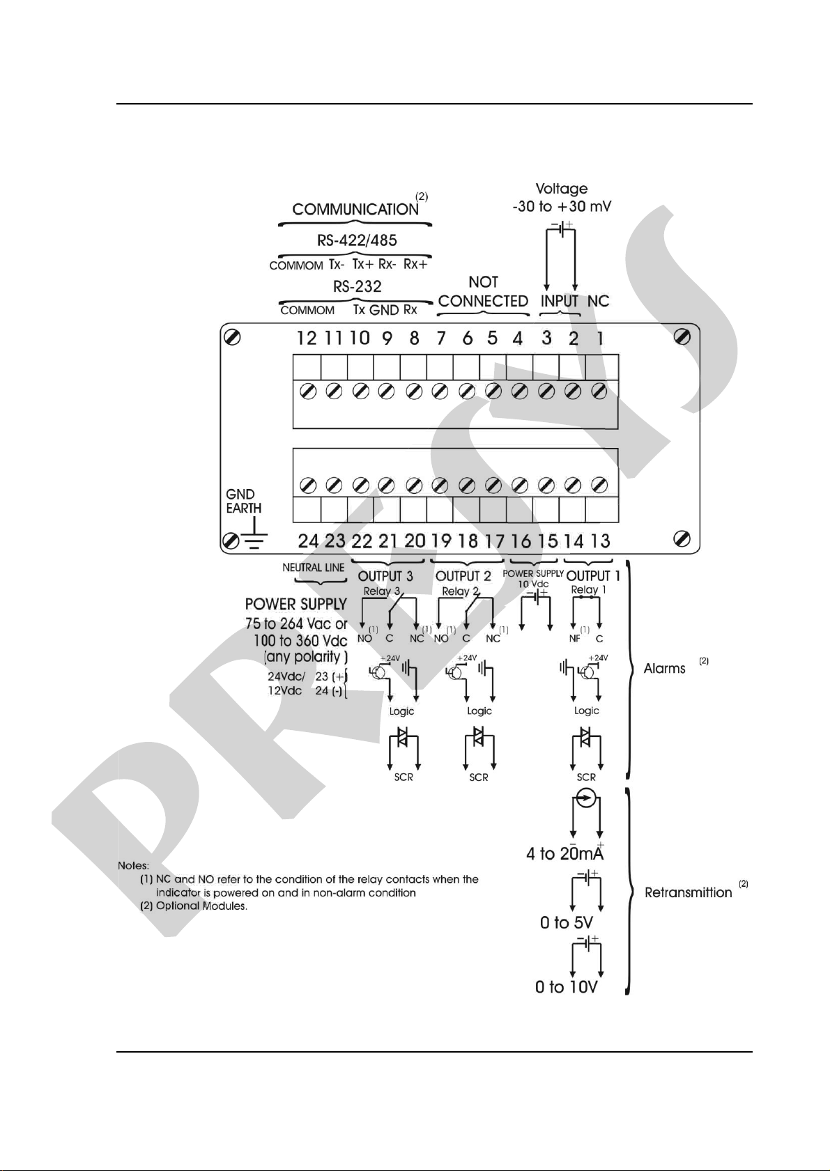
Input: One input for -30 to +30 mVdc.Input impedance of 10 M.
Outputs:
One 4 to 20mA, 1 to 5Vdc or 0 to 10Vdc analog retransmitter optional module
galvanically isolated up to 300Vac from power supply and input.
Alarm with a SPST relay rated for 3A at 220Vac.It is possible to use one
optional alarm module by replacing the retransmitter output.
Alarms with SPDT relays rated for 3A at 220Vac.It is possible to use up to 2
optional alarm modules.
Logic signal, open collector transistor, 24Vdc, 40mA max. with isolation.
Solid state relay rated for 2A at 250Vac with isolation.
10Vdc voltage source module to power the load cell.
Load cell voltage source:
10 Vdc/100 mA maximum, isolated from outputs, with short-circuit protection.
Serial Communication:
RS-232 or RS-485, with 50Vdc isolation, as an optional module connected to the
CPU board. MODBUS®- RTU Communication Protocol.
Indication:
Standard indication within the -9999 to 19999 range.
Configuration:
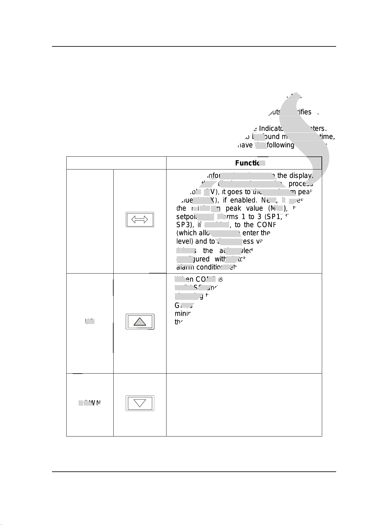
By front panel push-buttons and internal jumpers (for outputs).
Sampling rate:
64ms sampling rate, for the indication of input in -9999 to 19999 range. The
display is updated each 0.2 second.
Accuracy:
0.1% of full scale for the mV input.
0.5% of full scale for analog retransmitter output and 750maximum load.
Thermal stability:
0.005% / C of span with reference of 25C ambient temperature.
Power supply:
Universal 75 to 264Vac or 100 to 360Vdc (any polarity), 10W nominal; 24Vdc,
12Vdc and other values are optional.
-CC indicator with one SPDT relay which can be
presys
-CC indicator with one SPDT relay which can be
used as a high, low or deviation alarm, 75 to 264Vac or 100 to 360Vdc power supply
presys
used as a high, low or deviation alarm, 75 to 264Vac or 100 to 360Vdc power supply
Input impedance of
presys
Input impedance of
One 4 to 20mA, 1 to 5Vdc or 0 to 10Vdc analog retransmitter optional module
presys
One 4 to 20mA, 1 to 5Vdc or 0 to 10Vdc analog retransmitter optional module
galvanically isolated up to 300Vac from power supply and input.
presys
galvanically isolated up to 300Vac from power supply and input.
Alarm with a SPST relay rated for 3A at 220Vac
presys
Alarm with a SPST relay rated for 3A at 220Vac
It is possible to use one
presys
It is possible to use one
optional alarm module by replacing the retransmitter output.
presys
optional alarm module by replacing the retransmitter output.
Alarms with SPDT relays rated for 3A at 220Vac
presys
Alarms with SPDT relays rated for 3A at 220Vac
It is possible to use up to 2
presys
It is possible to use up to 2
optional alarm modules.
presys
optional alarm modules.
Logic signal, open collector transistor, 24Vdc, 40mA max. with isolation.
presys
Logic signal, open collector transistor, 24Vdc, 40mA max. with isolation.
Solid state relay rated for 2A at 250Vac with isolation.
presys
Solid state relay rated for 2A at 250Vac with isolation.
10Vdc voltage source module to power the load cell.
presys
10Vdc voltage source module to power the load cell.
Load cell voltage source:
presys
Load cell voltage source:
Vdc/100 mA maximum, isolated from outputs, with short-circuit protection.
presys
Vdc/100 mA maximum, isolated from outputs, with short-circuit protection.
Serial Communication:
presys
Serial Communication:
-232 or RS-485, with 50Vdc isolation, as an optional module connected to the
presys
-232 or RS-485, with 50Vdc isolation, as an optional module connected to the
CPU board. MODBUS
presys
CPU board. MODBUS
- RTU Communication Protocol.
presys
- RTU Communication Protocol.
®- RTU Communication Protocol.
®
presys
®- RTU Communication Protocol.
®
Standard indication within the -9999 to 19999 range.
presys
Standard indication within the -9999 to 19999 range.
Configuration:
presys
Configuration:
By front panel push-buttons and internal jumpers (for outputs).
presys
By front panel push-buttons and internal jumpers (for outputs).
Sampling rate:
presys
Sampling rate:
64ms sampling rate, for the indication of input in -9999 to 19999 range. The
presys
64ms sampling rate, for the indication of input in -9999 to 19999 range. The
display is updated each 0.2 second.
presys
display is updated each 0.2 second.
Accuracy:
presys
Accuracy:
0.1% of full scale for the mV input.
presys
0.1% of full scale for the mV input.
0.5% of full scale for analog retransmitter output and 750
presys
0.5% of full scale for analog retransmitter output and 750
Thermal stability:
presys
Thermal stability:
Power supply:
presys
Power supply:
Universal 75 to 264Vac or 100 to 360Vdc (any polarity), 10W nominal; 24Vdc,
presys
Universal 75 to 264Vac or 100 to 360Vdc (any polarity), 10W nominal; 24Vdc,