Metso NP700/B User manual

Positioners
Series NP700
Installation, Maintenance and
Operating Instructions
7 NP 72 en • 11/2014

27 NP 72 en
READ THESE INSTRUCTIONS FIRST!
These instructions provide information about safe handling and operation of the positioner.
If you require additional assistance, please contact the manufacturer or manufacturer's representative.
Addresses and phone numbers are printed on the back cover.
SAVE THESE INSTRUCTIONS!
Subject to change without notice.
All trademarks are property of their respective owners.
Table of Contents
1 INTRODUCTION ...................................................3
1.1 General .....................................................................3
1.2 Principle of operation .........................................3
1.3 Marking of positioner ..........................................3
1.4 Technical specifications .....................................4
1.5 Approvals ................................................................4
1.6 Recycling and disposal .......................................4
1.7 Safety precautions ...............................................4
2 MOUNTING ON THE METSO ACTUATOR ............4
2.1 General .....................................................................4
2.2 Installing positioner NP700/S1 on
Metso actuators with VDI/VDE 3845
mounting face ........................................................5
2.3 NP_700/700 positioner/limit switch
combination (Obsolete since 2013)................5
2.4 Piping of supply air ..............................................5
2.5 Instrument air supply ..........................................8
3 INPUT SIGNAL AND DIRECTIONS OF
OPERATION ..........................................................8
3.1 Changeover piece ................................................8
3.2 Cam plate ................................................................8
4 PRELIMINARY ACTIONS FOR THE
ADJUSTMENT .......................................................8
4.1 Position of the changeover piece ...................8
4.2 Pilot valve ................................................................8
4.3 Position of the cam plate ...................................9
5 BASIC ADJUSTMENT ...........................................9
6a
0ADJUSTMENT ..................................................9
7 SPLIT-RANGE ADJUSTMENT .............................10
8 MAINTENANCE ..................................................10
8.1 Supply air filter ................................................... 10
8.2 Pilot valve ............................................................. 10
8.3 Replacement of the diaphragms ................. 11
9 TROUBLESHOOTING .........................................11
10 OPTIONS .............................................................11
10.1 NP700/B and NP700/B1 ................................... 11
10.2 NP700/GN natural gas construction ........... 11
10.3 NP700/R dust-proof construction (IP65) ... 11
10.4 NP700/A with pressure gauges .................... 11
11 TOOLS ................................................................ 11
12 ORDERING SPARE PARTS ................................. 11
13 DRAWINGS AND PARTS LISTS .......................... 12
13.1 Exploded view and parts list ..........................12
13.2 Mounting parts for B1C6-502 and
B1J8-322 actuators (S1) ....................................14
13.3 Mounting parts for Quadra-Powr®
actuators (S1) .......................................................15
13.4 Mounting parts for B1C6-20 and
B1J8-20 actuators (S2) ......................................16
13.5 Mounting parts for B1C25-502 and
B1J25-322 actuators (S2) .................................17
14 TYPE CODE ........................................................ 18

7 NP 72 en 3
1 INTRODUCTION
1.1 General
The NP700 positioner is used for positioning double or sin-
gle acting actuator.
1.2 Principle of operation
Operation is based on the force balance principle. One force
is caused by the signal pressure (IN) and acts on the dia-
phragm (8), and the other is the compression force caused
by the feedback spring (60.1). The latter is directly propor-
tional to the position of the lower end of the spring, which
is in turn dependent solely on the position of the actuator
shaft via the lever (33), the cam (29), the positioner shaft
(26) and the coupling (52).
When the equilibrium between the forces mentioned
above is disrupted, the beam (5) moves in the direction of
the stronger force. The end of the beam moves the spool
(44.2) in the bore of the body (44.1). When diverted from
the equilibrium position, the spool guides the supply air to
one side of the actuator piston and the air on the other side
of the piston outside.
When the spool is in the equilibrium position the small vol-
ume of leakage past the spool creates an equal pressure on
either side of the unloaded cylinder piston. This pressure is
roughly 0,7 x the supply pressure.
If the signal pressure is altered, the spool moven out of the
equilibrium position and causes a pressure difference in the
cylinder. The piston moves in the direction of the difference
pressure until the compression force of the feedback spring
generated by the change in position is in equilibrium with
the force generated by the signal pressure.
Thus each signal pressure value corresponds to a single
actuator position. If an external force acts on the actuator
shaft, the shaft tends to move in the direction of the torque.
This alters the position of the spool via the feedback system
so that the pressure difference arising in the cylinder offsets
the effect of the external torque.
Parts list for Figure 1:
Item Part
5Beam
8Diaphragmpiston
26 Shaft
29 Cam plate
33 Lever
44.1 Pilot valve body
44.2 Pilot valve spool
46 Changeover piece
52 Coupling
60.1 Feed-back spring
60.3 Range adjustment
67 Zero adjustment
1.3 Marking of positioner
The positioner has an adhesive ID plate, see Fig. 2.
The ID plate contains the following information (from top to
bottom):
Full type designation of the positioner
Input signal
Max. supply presssure
Ambient temperature range
Manufacturing series number
An additional plate, Fig. 3, has markings:
Filter regulator (-K)
Temperature range
Fig. 1 Schematic diagram
Fig. 2 ID plate
Fig. 3 Additional plate
47 NP 72 en
1.4 Technical specifications
Signal pressure ranges 20-100 kPag, 0.2-1.0 barg,
(3-15 psig)
Split ranges 20-60 kPag/60-100kPag,
0.2–0.6 barg/0.6–1.0 barg,
(3–9 psig, 9–15 psig)
Turning angle of feed-back shaft max. 90°
Relation between angle and signal linear
Supply pressure ps 140-1000 kPag, 1.4–10 barg
(20–145 psi)
Effect of supply pressure < 0.2 % / 0.1 bar
(< 0.14 % / 1 psi)
Ambient temperature -40° to +90 °C
(-40° to +185 °F)
Effect of temperature < 0.07 % / °C
(< 0.025 % / °F)
Performance, measured using a cylinder
actuator with 12 % friction load
- dead band < 0.3 %
- hysteresis < 1.2 %
- linearity < 2 %
Effect of vibration (1.5 g, 5–100 Hz) < 1 %
Weight approx. 1.5 kg / 3.3 lb
Construction materials
- case anodized aluminium alloy
- cover polycarbonate (standard model)
- internal parts stainless steel, aluminium
alloy and stainless spring steel
- diaphragm and seals nitrile rubber (standard model)
1.5 Approvals
NP700/B construction has CENELEC EEx d IIC T5/T6
approval.
NP700/B1 construction has CSA Class I, Div. 1, Gr. B, C and
D approval and
FM Class I, Div. 1, Gr. B, C and D approval.
CENELEC = European Committee for Electrotehnical Stand-
ardization
CSA = Canadian Standards Association
FM = Factory Mutual
1.6 Recycling and disposal
Most positioner parts can be recycled if sorted according to
material. Most parts have material marking. A material list is
supplied with the positioner. In addition, separate recycling
and disposal instructions are available from the manufac-
turer. A positioner can also be returned to the manufacturer
for recycling and disposal against a fee.
1.7 Safety precautions
2 MOUNTING ON THE METSO ACTUATOR
2.1 General
When the positioner is supplied together with the valve and
actuator, the tubes are mounted and the positioner adjusted in
accordance with the customer's specifications.
When the positioner is ordered separately, the mounting parts
for the assembly must be ordered at the same time.
Example order: Positioner alone (BC12)-Z-NP724.
The positioner is equipped with VDI/VDE 3845 (S1) mount-
ing face.
This mounting face requires a shaft with the H coupling.
Old Metso Automation mounting face (S2) is no more avail-
able.
For mounting parts for Metso actuators, see Sections
13.2–13.3.
Table 1 Pilot valve alternatives
Positioner
type
Actuator
stroke volume
dm3(litres)
Air
consumption
nm3/h / scfm *)
Max. delivery
nm3/h / scfm *)
NP723 0.3–10 0.6 / 0.3 12 / 7
NP724 1.0–8.0 0.6 / 0.3 12 / 7
NP726 8.0–30.0 0.9 / 0.5 18 / 10.4
NP727 > 30 1.8 / 1.0 32 / 18.6
*) supply pressure 4 bar / 60 psi
CAUTION:
Do not exceed the positioner performance limitations!
Exceeding the limitations marked on the positioner may
cause damage to the posioner, actuator and valve.
Damage or personal injury may result.
CAUTION:
Do not dismantle a pressurized positioner!
Dismantling a pressurized positioner will result in uncon-
trolled pressure release. Always isolate the relevant part of
the pipeline, release the pressure from the positioner and
the piping.
Failure to do this may result in damage or personal injury.
CAUTION:
Beware of the moving parts when positioner is oper-
ated!
7 NP 72 en 5
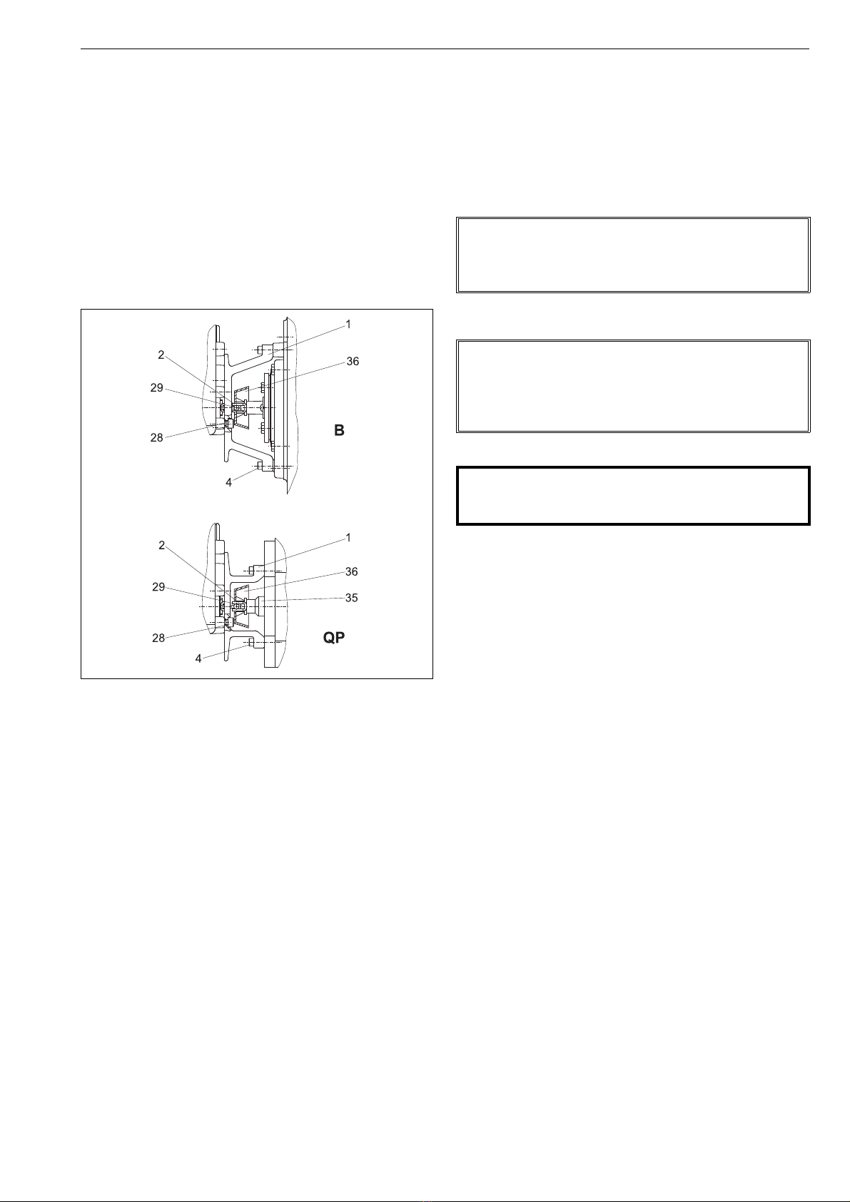
2.2 Installing positioner NP700/S1 on
Metso actuators with VDI/VDE 3845
mounting face
1. The actuator piston must be in the up position (in spring-
return actuators as determined by the spring).
2. Install the pointer (only B_U) parallel with the valve clo-
sure member and fasten the draught piece (2) with a
screw (29) to the pointer cover (B_U) or to the coupling
(QP), as shown in Fig. 4. Secure the draught piece fasten-
ing screw with a sealant (e.g. Loctite) and tighten it
properly.
3. Fasten the mounting bracket (1) to the positioner.
4. Fasten the mounting bracket (1) to the actuator.
2.3 NP_700/700 positioner/limit switch
combination (Obsolete since 2013)
The bottom of the limit switch acts also as the cover for the
positioner. Remove the limit switch before the adjustment
of the positioner.
1. Loosen the cover screws. Note the position of the shaft
relative to the positioner when removing the limit switch.
2. When the adjustment of the positioner is done, operate
the actuator until the valve is in the closed or open posi-
tion.
3. Note the position of the actuator and valve when
mounting the limit switch on the actuator. Make sure
that the position of the shaft is unchanged relative to
the positioner.
4. Place the limit switch on the positioner so that the
shafts are correctly engaged.
5. Fasten the cover screws.
6. Check the adjustment of the limit switch. See the
instruction manual of the limit switch for details.
2.4 Piping of supply air
Table 2 provides the recommended pilot valve and tube
sizes in accordance with the actuator sizes. Tube sizes are
minimum values allowed.
Connect air supply to S (1/4 NPT).
Connect C1 and C2 (1/4 NPT) to the actuator according to
Fig. 5. See also Chapter 3.
Connect signal air to IN (1/4 NPT).
For pipe threads are liquid sealants, e.g. Loctite, recom-
mended.
2.5 Instrument air supply
The supply air must be clean, dry and oil-free instrument air,
e.g. according to standard ISA S7.3-81. Supply pressure is
1.4–10 bar (20–140 psi).
Fig. 4 Installing on a Metso actuator (S1)
NOTE:
A single action connection alone is permitted for position-
ers mounted on the spring actuator!
Place a plug in connection C1 or C2. See Figure 5.
NOTE:
Exessive sealant may cause faulty operation of the posi-
tioner.
Sealing tape is not recommended.
Ensure the cleaness of the air piping.
CAUTION:
Do not exceed the permitted actuator supply air pres-
sure!

67 NP 72 en
Table 2 Piping and operating times
Actuator
NPT
Piping Operating time / stroke (s)
pilot valve
Plastic/Cu/SS (mm) Plastic/Cu/SS (")
B1C Stroke vol.
dm3/in36/4 10/8 12/10 1/4 3/8 1/2 ø4LC ø4 ø6 ø6 HC
6 0.3/20 1/4 x x 1 1
9 0.6/37 1/4 x x 1.5 1.5
11 1.1/67 3/8 x x 2 2
13 2.3/140 3/8 x x 4
17
20
4.3/262
5.4/330
1/2 x
x
x
x
7
8.5
(6)
(5.5)
25
32
10.5/640
21/1282
1/2
3/4
x
x
(x)
(x)
x
x
(x)
(x)
10
17
(8.5)
(16)
40
50
43/2624
84/5130
3/4
1
x
x
(x)
(x)
x
x
(33)
(60)
31
57
502 195/11900 1 x x
B1J
B1JA
Stroke vol.
dm3/in3NPT 6/4 10/8 12/10 1/4 3/8 1/2 ø4LC ø4 ø6 ø6 HC
6 0.47 / 28.7 1/4 x x 1 1
8
10
0.9/55
1.8/111
3/8 x
x
x
x
1.5/3 1.5/3
2.5/5.5
12
16
3.6/225
6.7 / 415
1/2 x
x
x
x
4.5/11
8/18
(3.5/6)
(4.5/11)
20
25
13/795
27 / 1642
3/4 x
x
(x)
(x)
x
x
(x)
(x)
8.5/21
17/38
(7.5/19)
(15/33)
32
322
53 / 3231
106 / 6480
1x
x
(x) x
x
(33/74) 30/64
60/130
QP Stroke vol.
dm3/in3NPT 6/4 10/8 12/10 1/4 3/8 1/2 ø4LC ø4 ø6 ø6 HC
1C 0.62/38 3/8 x x 1.5/2 1.5/2 - -
2C 1.08/66 3/8 x x 2/3.5 2/3.5 - -
3C 2.18/133 3/8 x x - 3/5 2/3 -
4C 4.34/265 3/8 x x - 6/10 4/6 -
5C 8.7/531 3/8 x x - - 7/10
6C 17.5/1068 3/4 x x - 12/18 10/15
Times in parenthesis are achieved by changing pilot valve alone or pilot valve and tube size.
Operating times for spring return actuators B1J/B1JA and QP:
against the spring / direction of the spring
Actuator without valve:
ps= 0.4–0.5 bar / 58 - 72 psi
Step of input signal:
pi= 0-100 % and 100-0 %
7 NP 72 en 7
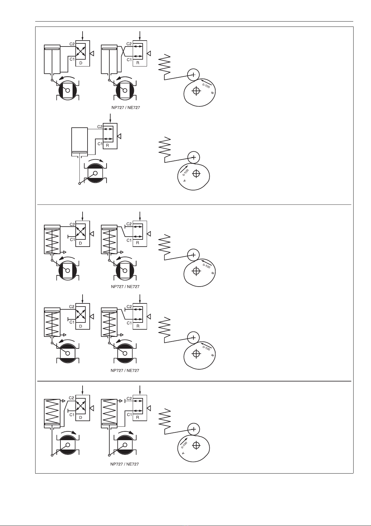
Fig. 5 Positioner actions
NOTE: In positioner NP727 the changeover piece can be used in position R only.
DOUBLE-ACTING
1. Increasing input signal to open valve.
Cam segments:
B/0-100, A/0-50, A/50-100
2. Increasing input signal to close valve.
Cam segments:
A/0-100, B/0-50, B/50-100
NOTE:
Reverse piping for ST actuators.
SINGLE-ACTING
(SPRING TO CLOSE)
3. Increasing input signal to open valve.
Spring to close valve.
Cam segments:
B/0-100, A/0-50, A/50-100
4. Increasing input signal to close valve.
Spring to open valve.
Cam segments:
B/0-100, A/0-50, A/50-100
WARNING:
Valve closes exceptionally counterclockwise.
Unsuitable for Q, R, T5, F and L series valve
NOTE:
Reverse piping for ST actuators. Spring and
piston in the opposite position from shown.
SINGLE-ACTING
(SPRING TO OPEN)
5. Increasing input signal to close valve.
Spring to open valve.
Cam segments:
A/0-100, B/0-50, B/50-100
NOTE:
Reverse piping for ST actuators. Spring and piston in
the opposite position from shown.

87 NP 72 en
3 INPUT SIGNAL AND DIRECTIONS OF
OPERATION
Figure 6 assists in choosing the right segment for the cam
plate (29) and position for the changeover piece (46).
3.1 Changeover piece
The function of connection C1 and C2 can be altered by
turning the changeover piece (46). The diagram D (or R)
shown on the protective plate (48) functions when the sym-
bol D (or R) is visible in the lower lefthand corner of the
changeover piece (46).
D = direct, R = reverse.
External changes in the tubes are not needed. Positioner
NP727 is an exception (DIA6HC pilot valve). Then the
changeover piece must always be in position R and the
external tubes mounted in accordance with Fig. 5.
3.2 Cam plate
The figures marked on the cam plate (29) are the signal
ranges expressed as percentages, for example 0-100 corre-
sponds to 0.2–1.0 bar (3-15 psi), or 50-100 to 0.60-1.0 bar (9-
15 psi), see Fig. 6.
The arrows on the cam show the direction it must turn
when the input signal is rising in the cam segment in ques-
tion.
The non-rising segments between the rising segments are
roughly 15-20°.
4 PRELIMINARY ACTIONS FOR THE
ADJUSTMENT
Set the valve’s open and closed limits with the actuator lim-
iter screws; see the valve instruction manual. The changeo-
ver piece (46) and the cam (29) must be in correct positions.
Check the pilot valve size from Table 2.
The adjustment must always be carried out when the sup-
ply pressure has been changed.
Please note that operating of the valve is required during
the adjustment.
4.1 Position of the changeover piece
Choose the position of the changeover piece, D or R, from
Fig. 7 in accordance with the function desired.
Turn the changeover piece (46) when necessary.
Loosen the nuts (49) and remove the protective plate (48).
Pull out the changeover piece (46). Check the O-rings (47, 2
pcs.) and apply silicone grease lightly if needed. Place the
changeover piece (46) and the protective plate (48) in the
case. Tighten the nuts (49) evenly, one after the other.
4.2 Pilot valve
Removal of the pilot valve is unnecessary when the change-
over piece is turned around. For instructions of removal, see
Section 8.2.
4.3 Position of the cam plate
Choose the side, A or B, and the rising segment of the cam
plate from Fig. 7 in accordance with the function desired.
Move the actuator piston to the end where the input signal
has its lower value. Shut off the supply pressure or move the
pilot spool by deflecting the beam (5) gently so that the pis-
ton strokes to the desired limit. The input signal should be
zero or at the lower limit.
Fig. 6 Input signal ranges, the cam plate (29).
50 - 100
0 - 100
0 - 50
B
~ 15°
~ 15°
~ 15°
~ 15°
~ 15°
~ 15°
segment C
segment E
segment D
segment C
segment E
0.2–0.6 bar (3–9 psi)
rising signal opens
0.20–1.0 bar (3–15 psi)
rising signal opens
0.2–1.0 bar (3–15 psi)
rising signal closes
0.60–1.0 bar (9–15 psi)
rising signal closes
0.6–1.0 bar (9–15 psi)
rising signal opens
0.2–0.6 bar (3–9 psi)
rising signal closes
CAUTION:
Do not dismantle a pressurized positioner!
NOTE:
Check that the changeover piece is mounted correctly:
Symbol D or R is visible in the lower left hand corner.
Fig. 7 Mounting the changeover piece
47 49 48
46
45
44
43

7 NP 72 en 9
Loosen the screw (57), remove the indicator (32), loosen the
screw (31) and the locking wheel (30). Turn the cam plate
(46) to the desired side.
In case of α0adjustment proceed acc. to Sections 6.1 and
6.2.
Place the roller so that its contact point is 1 mm (0.04") from
the beginning of the rising segment. Then tighten the lock-
ing wheel (30) and the screw (31).
5 BASIC ADJUSTMENT
Basic adjustment is made to rotary and butterfly valves.
Please note the procedures in Chapter 4 before the adjust-
ment.
1. Switch on the supply pressure (S) and the input signal
(IN).
2. Set the input signal at the closed limit of the valve so
that it is 2 % i.e. 0.02 bar (0.2 psi) higher or lower than
the limit value, e.g. 0.2 + 0.02 = 0.22 bar (3 + 0.2 = 3.2 psi)
or 1.0 - 0.02 = 0.98 bar (15 - 0.2 = 14.8 psi). Loosen the
screw (56). Turn the zero adjustment screw (67) so that
the actuator comes slowly to the closed limit. Tighten
the screw (56) always after the zero adjustment. The
valve should open slightly with a 4 % change in signal,
that is 0.03 bar (0.5 psi), e.g. 0.2 + 0.03 = 0.23 bar (3 + 0.5
= 3.5 psi) or 1.0 - 0.03 = 0.97 bar (15 - 0.5 = 14.5 psi). See
Figures 8 and 9.
3. Set the input signal to the other limit value. The valve
should be entirely open at 100 %, i.e. 1.0 bar (15 psi) or
0.2 bar (3 psi). The valve should start to operate to
closed direction at 98 %, i.e. 0.98 bar (14.0 psi) or 0.22
bar (3.2 psi). The range, i.e. turning angle, changes when
the effective lenght of the spring (60) is increased or
decreased by turning the range adjustment nut (60.3).
See Fig. 9.
4. The zero and range adjustments affect each other, so
stages 2 and 3 must be repeated a few times.
5. Screw on the pointer (32) into place so that the yellow
line is in the direction of the valve closing member.
Tighten the screw (57).
6α0ADJUSTMENT
α0adjustment is made to segment and ball valves. This
adjustment takes into account the "dead angle" α0of the
ball valve. The entire signal range is then used for effective
The same adjustment method can be applied to butterfly
valves in papermills for pulp flow control to avoid the dewa-
tering of the pulp near the closed position of the disc.
Table 3 shows the shift on the circumference of the cam
equal to the "dead angle" of the valve, Figure 11, in various
cam segments (C, E, D).
Please note the procedures in Chapter 4 before the adjust-
ment.
1. Mark the shift in question on the edge of the cam, Fig. 11
and Table 3. Dimensions do not have to be measured if
the dead angle can be reliably noticed from position of
the closing member.
2. Lock the cam so that the roller touches the edge of the
Fig. 8 Basic and
α
0adjustments
POSITION %
Rising input signal closes valve Rising input signal opens valve
max 2 %
INPUT SIGNAL %
safety range 2 %
Basic adjustment α0adjustment
Fig. 9 Zero and range adjustments
Fig. 10 Dead angle
Fig. 11 Shift on circumference of cam equal to dead angle
range increases
range
range decreases
screw (56)
zero adjustment (67)
adjustment (60.3)
α0= dead angle
segment D
segment C
segment E
shift
Roller contact point when
the ball is completely closed

10 7 NP 72 en
cam plate at the mark. Tighten the locking wheel (30)
and the screw (31).
3. Switch on the supply pressure (S) and the input signal
(IN).
4. Set the input signal at the closed limit of the valve so
that it is 2 % i.e. 0.02 bar (0.2 psi) higher or lower than
the limit value, e.g. 0.2 + 0.02 = 0.22 bar (3 + 0.2 = 3.2 psi)
or 1.0 - 0.02 = 0.98 bar (15 - 0.2 = 14.8 psi). Loosen the
screw (56). Turn the zero adjustment screw (67) so that
the actuator comes slowly to the closed limit. Tighten
the screw (56) always after the zero adjustment. The
valve should open slightly with a 4 % change in signal,
that is 0.03 bar (0.5 psi), e.g. 0.2 + 0.03 = 0.23 bar (3 + 0.5
= 3.5 psi) or 1.0 - 0.03 = 0.97 bar (15 - 0.5 = 14.5 psi). See
Figure 9.
5. Set the input signal to the other limit value. The valve
should be entirely open at 100 %, i.e. 1.0 bar (15 psi) or
0.2 bar (3 psi). The valve should start to operate to
closed direction at 98 %, i.e. 0.98 bar (14.0 psi) or 0.22
bar (3.2 psi).
The range, i.e. turning angle, changes when the effective
lenght of the spring (60) is increased or decreased by turn-
ing the range adjustment nut (60.3). See Fig. 9.
6. The zero and range adjustments affect each other, so
stages 4 and 5 must be repeated a few times.
7. Screw on the pointer (32) into place so that the yellow
line is in the direction of the valve closing member.
Tighten the screw (57).
7 SPLIT-RANGE ADJUSTMENT
In principle, split range adjustments are made in the same
manner as for a normal signal range. Select a split range,
20-60 kPag / 0.2–0.6 barg / 3–9 psig or 60-100 kPag /
0.6–1.0 barn / 9–15 psig, from the cam plate. See Figure 6.
8 MAINTENANCE
Regular maintenance is not necessary.
The need for maintenance depends on the quality of the
instrument air. See also Section 2.5.
If there is need for servicing proceed according to the fol-
lowing sections.
8.1 Supply air filter
The supply air filter (50) is located in the supply air connec-
tion (S); the filter can be removed for cleaning.
8.2 Pilot valve
Remove the pilot valve (44) by first loosening the nuts (49),
and then by lifting off the protective plate (48), the change-
over piece (46) and the gasket (45).
Table 3 Dead angle in degrees
Valve
size
Valve series
MBV
QMBV
1)
MBV
QMBV
2)
D
3)
T5,
QT5 QXT5 T25,
QT25 QXT25 R,
QR
mm mm Dead angle in degrees
25 1 12.5 - - 23.0 17.5 - - 14
40 1 1/2 11.0 - - 22.0 11.0 - - 11
50 2 9.0 8.0 12.0 22.0 11.0 16.0 7.0 15
6521/28.0------11
80 3 9.0 7.0 11.0 16.0 7.0 15.0 8.0 8
100 4 9.0 7.0 11.0 15.0 7.5 14.5 8.0 7
125511.0----11.06.07
150 6 9.0 7.0 10.5 14.5 8.0 12.0 7
200 8 8.0 6.5 7.5 11.0 6.0 8.5 6
250 10 8.0 6.5 7.0 12.0 8.5 6
300 12 7.0 5.5 5.5 8.5 7.0 5
350 14 5.4 5.5 - 4
400 16 4.5 5.0 8.5(14") 4
450 18 5.0 7.0 (16")
500 20 5.5
600 24 5.0
650 26 6.0
700 28 6.0
750 30 5.5
800 32 -
900 36 4.5
1) Seat supported 2) Trunnion 3) S/G seat
Table 4 Shift caused by dead angle, mm/inch
α0Segment C Segment E Segment D
20° *) 6.1/0.24 8.1/0.31
19° *) 5.8/0.22 7.7/0.30
18° *) 5.5/0.21 7.3/0.28
17° *) 5.2/0.20 6.9/0.27
16° *) 4.9/0.19 6.5/0.25
15° 3.1/0.12 4.6/0.18 6.1/0.24
14° 2.9/0.11 4.3/0.16 5.7/0.22
13° 2.7/0.10 4.0/0.15 5.3/0.20
12° 2.5/0.09 3.7/0.14 4.9/0.19
11° 2.3/0.09 3.4/0.13 4.5/0.17
10° 2.1/0.08 3.1/0.12 4.1/0.16
9° 1.9/0.07 2.8/0.11 3.7/0.14
8° 1.7/0.06 2.5/0.09 3.3/0.12
7° 1.5/0.05 2.2/0.08 2.9/0.11
6° 1.3/0.05 1.9/0.07 2.5/0.09
5° 1.1/0.04 1.6/0.06 2.1/0.08
4° 0.9/0.03 1.3/0.05 1.7/0.06
*) Segment C: α0max. 15°
CAUTION:
Do not dismantle a pressurized positioner!
NOTE:
Ensure the cleanness of the air piping.

7 NP 72 en 11
The pilot valve spool (44.2) should slip easily in the pilot
valve body (44.1).
If the pilot valve sticks, wash the body and spool with sol-
vent.
See the exploded view for the correct installation position
of the pilot valve. The size code for the pilot valve on the
body, for example DIA 4.0, must be visible on the right side.
Check the condition of the O-rings (43, 47) and of the gas-
ket (45). The end of the leaf spring on the beam must be on
top of the pilot valve spool, Figure 7. Make sure that the end
of the beam (5) goes into the spool groove without side-
ways deflections. After tightening the nuts (49), check the
beam once again by hand to see that the pilot valve moves
readily.
8.3 Replacement of the diaphragms
Remove the feedback spring (60), loosen the screws (23)
and remove the screw (15). Replace the diaphragm (14).
Note the correct installation position for the diaphragm,
with the convolution downward. See Figure 12.
Check the condition of the washer (55) when assembling
and secure the upper spring plate (16) with e.g. Loctite.
Check that the O-ring (11) is in place. Tighten the cover
screws (23) evenly. The positioner adjustment should be
checked after replacement of diaphragm.
Note. O-ring (11) in the old construction only (manufac-
tured before 12/94)
9 TROUBLESHOOTING
1. Signal pressure change does not affect actuator position
supply pressure too low
signal pressure tubes leak
diaphragm damaged
pilot valve sticks
changeover piece seals leak
tube installations between positioner and actuator
changeover piece or cam position wrong, see Fig. 6.
actuator or valve jammed
2. The actuator reaches final position with a small signal
pressure change
the tube installation between positioner and actua-
tor, the changeover piece or the cam position wrong.
3. Inaccurate positioning
pilot valve dirty
beam (5) pushes pilot valve spool sideways
diaphragm damaged
actuator torque too low
supply pressure too low
valve torque requirement increased
4. Overshooting or too slow positioning
pilot valve dirty or wrong size, see Table 2
supply air tube too small or supply air filter dirty
valve sticks
10 OPTIONS
10.1 NP700/B and NP700/B1
Equipped with a flameproof enclosure I/P converter.
To be adjusted like for standard posioners. Do not make any
adjustments for the I/P converter!
10.2 NP700/GN natural gas construction
For clean "sweet" natural gas instead of compressed air. Like
standard construction but with 3/4 NPT exhaust port.
Please note: do not remove the exhaust port (4).
10.3 NP700/R dust-proof construction (IP65)
For extremely dusty environments. The protective cover (3)
behind the standard posioner is replaced with an exhaust
port. The port has a 3/4 NPT filter.
Please note: do not remove the exhaust port (3).
10.4 NP700/A with pressure gauges
A standard positioner can be equipped with a pressure
gauge block.
The block (70) is attached with tree sef-tapping screws (72).
The O-rings (71, 3 pcs.) must be in position before mount-
ing. Check tightness after mounting.
For all other constructions see Type Code, Chapter 14.
11 TOOLS
In addition to standard general tools, you need the follow-
ing equipment:
calibration device for adjustments
12 ORDERING SPARE PARTS
When ordering spare parts, always include the following
information:
type code, sales order number, serial number
number of the parts list, part number, name of the
part and quantity required
This information can be found from the identification plate
or documents.
NOTE:
The pilot valve body and spool constitute a pair, and must
not be replaced separately.
Fig. 12 Replacement of diaphragms
NOTE:
gap required
11 14 55 15 22 23
5
16
60

12 7 NP 72 en
13 DRAWINGS AND PARTS LISTS
13.1 Exploded view and parts list
65
26
26
88 87 86
NP700/J
4
68, 99
64, 101
3, 69,98
NP700/S1
NP700/R
NP700/GN
43
4
3
27 28
50
62
77 78 79
72
70
71
73
74
76
NP700-K
NP700/A
100
43
44
45
47
46
48
49
109
110
2
29
30
31
32
57
105
58
5
6
59
16
60
51
34
33
56
67
14
15
55
10
8
7
22 23
22 75
54
18
22
23
37
115
116
NP700/B, -/B1
NP700/B-L
NP700/A
1

7 NP 72 en 13
Spare part category 1: Parts for basic maintenance. Delivered as a set.
Spare part category 2: Parts for spool valve and cover replacement.
Spare part category 3: Parts for shaft replacement.
Item Qty Description Spare part
category
1 1 Housing assembly
21Cover 2
31Protectivecover
1Exhaustport
41Screw
5 1 Beam assembly
61Plate
72Screw
81Lowerdiaphragmplate 1
10 1 Upper diaphragm plate
13 *) 1 O-ring
14 1 Diaphragm 1
15 1 Screw
16 1 Upper spring plate
18 3 O-ring
22 1 Diaphragm cover
23 3 Screw
26 1 Shaft assembly 3
27 1 Washer
28 1 O-ring 1
29 1 Camplate
30 1 Locking wheel 1
31 1 Screw
32 1 Pointer
33 1 Lever assembly
34 1 Retaining ring 1
37 1 I/P converter
43 1 O-ring 1
44 1 Pilot valve assembly 2
45 1 Gasket 1
46 1 Changeover piece
47 2 O-ring 1
48 1 Protective plate
49 2 Hexagon nut
50 1 Filter
51 2 Bearing
Item Qty Description Spare part
category
55 1 Gasket 1
56 1 Screw
57 1 Grub screw
58 1 Support plate
59 2 Barrel nut
60 1 Spring
62 1 Hexagon plug
64 1 Body
65 1 Lock ring
67 1 Zero screw
68 2 Spring
69 2 Guide
70 1 Pressure gauge block
71 3 O-ring
72 3 Screw
73 1 Pressure gauge
74 2 (1) Pressure gauge
75 1 Pressure gauge
76 1 Double fitting
77 1 Filter regulator
78 1 Reduction fitting
79 1 Pressure gauge
86 1 Adapter plate
87 2 Washer
88 2 Screw
98 2 Screw
99 2 Spring plate
100 1 Additional plate
101 2 O-ring
105 1 ID plate
109 1 Seal
110 4 Screw
115 2 Washer
116 2 Screw
*) Only in positioners manufactured before 12/94
14 7 NP 72 en
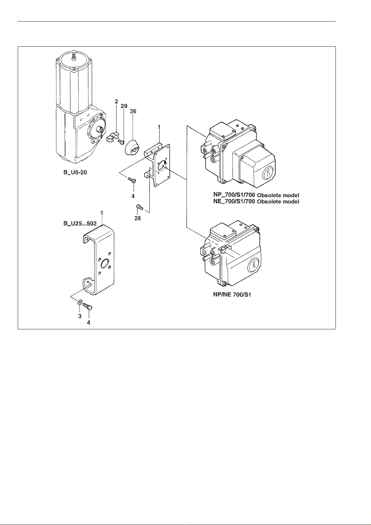
13.2 Mounting parts for B1C6-502 and
B1J8-322 actuators (S1)
Item Qty Description
1 1 Mounting bracket
21Draughtpiece
34Washer
44Screw
28 4 Screw
29 2 Screw
36 1 Coupling jacket
7 NP 72 en 15
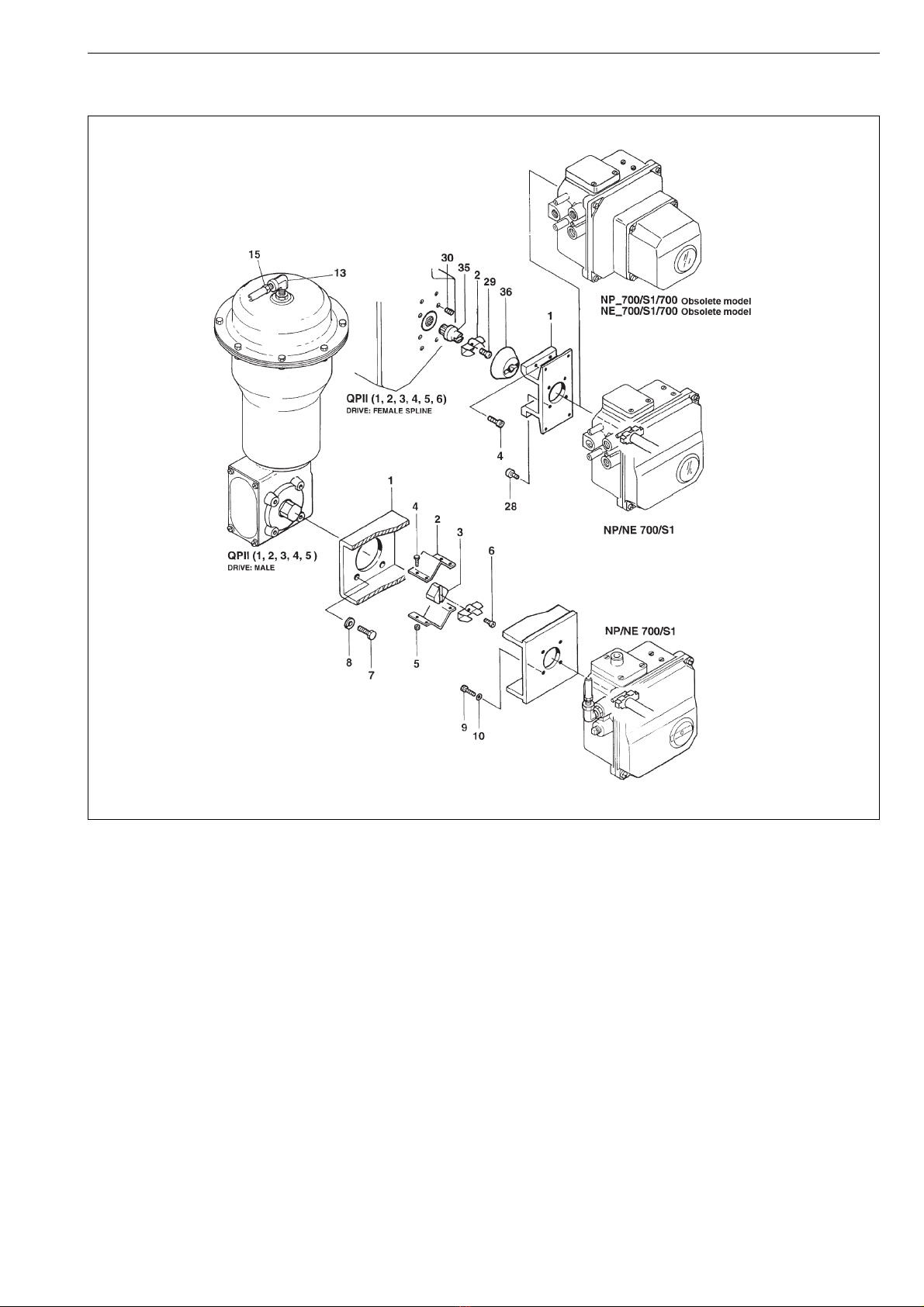
13.3 Mounting parts for Quadra-Powr®
actuators (S1)
Drive: male
Item Qty Description
1 1 Mounting bracket
2 2 Coupling half
31Adapter
44Screw
54Hexnut
61Screw
74Screw
84Washer
94Screw
10 4 Washer
Drive: female spline
Item Qty Description
1 1 Mounting bracket
21Ear
44Screw
28 4 Screw
29 1 Screw
30 (4) Screw
35 1 Coupling
36 1 Coupling jacket

16 7 NP 72 en
13.4 Mounting parts for B1C6-20 and
B1J8-20 actuators (S2)
Item Qty Description
1 1 Mounting bracket
21Draughtpiece
32Washer
42Screw
51Bracket
61Washer
71Screw
82Washer
10 1 Rod
11 2 Bushing
12 2 Screw
13 2 Stud (B1C6 only)
14 2 Hexagon nut (B1C6 only)
26 2 Locking nut
27 2 Washer
28 2 Screw

7 NP 72 en 17
13.5 Mounting parts for B1C25-502 and
B1J25-322 actuators (S2)
Item Qty Description
1 1 Mounting bracket
21Draughtpiece
32(4)Washer
42(4)Screw
82Washer
92Screw
10 1 Rod
11 2 Bushing
12 2 Screw
26 2 Locking nut
27 2 Washer
28 2 Screw
18 7 NP 72 en
14 TYPE CODE
PNEUMATIC POSITIONER NP 700
1. 2. 3. 4. 5. 6.
NP724 /S1–K
1. PRODUCT GROUP
NP Pneumatic positioner
2. SERIES CODE
3. INPUT SIGNAL RANGE
04-20 mA, only with options B and B1 (6th sign).
220-100 kPag /0.2-1.0 barg / 3-15 psig.
4. PILOT VALVE SIZE CONNECTIONS
S, C1, C2
3Ø4 mm LC 1/4 NPT
4Ø4 mm 1/4 NPT
6Ø6 mm 1/4 NPT
7Ø6 mm HC 3/8 NPT
5. ACTION
Suitable for Double and Single action, without sign.
A
Single action, linear motion. Applicable ONLY to D/R series
spring diaphragm linear actuators, max. stroke size 57 mm
(2-¼ in).
6. OPTIONS
If several options below are needed to the same positioner,
the codes shall be marked in presented order from top.
Temperature range for various options shall be considered
carefully.
-Standard, (IP 54 enclosure). 6. sign S1 always to be defined
Temperature range -40 °C... +90 °C/ -40 °F...+194 °F.
B
Flameproof enclosure I/P-converter (IP65), ATEX EEx d IIC T6.
Input signal range 4-20 mA. M20x1,5 conduit entry.
3. sign always 0.
Temperature range -40 °C... +55 °C / -40 °F...+131 °F.
B1
Explosion proof enclosure I/P-converter (IP65), FM/CSA-
approval. Class 1, Div. 1, Groups B, C, D. Input signal range
4-20 mA. 1/2 NPT conduit entry. 3. sign always 0.
Temperature range -40 °C... +55 °C/ -40 °F...+131 °F.
GN For natural gas. Exhaust adapter, 3/4 NPT thread.
Not usable inside with options B and B1.
RWater and dustproof enclosure IP65/NEMA 4 and 4X.
Not available with option GN.
H
High temperature construction. Viton diaphragm and seals.
Not available with options B, B1, A, A1 and K.
Temperature range -10° to +120 °C/ +14° to +248 °F.
S1
Positioner with attachment face acc. to standard
VDI/VDE 3845, equipped with H-clip. When positioners are
separate deliveries, VDI/VDE ear is supplied.
Not applicable to globe valve actuators (5th sign A).
A
Pressure gauges, scale bar/psi/kPa, basic material brass, nickel
plated, housing stainless steel, glycerine filled. 5. sign always
to be defined.
Temperature range -40 °C... +70 °C / -40 °F... +158 °F.
Y2 Brass bearing of small lever arm.
J30 Square shaft and special mounting kit.
YSpecial construction.
-□ACCESSORIES
K
Filter regulator for supply air. Pressure gauge, scale bar/psi/
kPa, basic material brass, nickel plated, housing stainless steel,
glycerine filled.
Temperature range -40 °C... +82 °C / -40 °F... +180 °F.
Filter size 5 μm. Not available with HC-pilot (4. sign 7). Will be
specified in the option sticker.
In connection with the Ø6 HC-pilot valve (4. sign 7) must be
used large capacity filter regulator (not K) for actuator bigger
than BC 40 and BJ 32. Installation with mounting bracket.
CE01 PG11 / 1/2 NPT conduit entry nipple. Will be specified in the
option sticker.
CE02 PG11 / M20x1.5 conduit entry nipple. Will be specified in the
option sticker.
CE03 PG11 / R1/2 (PF1/2) conduit entry nipple. Will be specified in
the option sticker.

7 NP 72 en 19

Metso Flow Control Inc.
Europe, Vanha Porvoontie 229, P.O. Box 304, FI-01301 Vantaa, Finland. Tel. +358 20 483 150. Fax +358 20 483 151
North America, 44 Bowditch Drive, P.O. Box 8044, Shrewsbury, M A 01545, USA. Tel. +1 508 852 0200. Fax +1 508 852 8172
South America, Av. Independéncia, 2500-Iporanga, 18087-101, Sorocaba-São Paulo, Brazil. Tel. +55 15 2102 9700. Fax +55 15 2102 9748
Asia Pacic, Haw Par Centre #06-01, 180 Clemenceau Avenue, Singapore 239922. Tel. +65 6511 1011. Fax +65 6250 0830
China, 11/F, China Youth Plaza, No.19 North Rd of East 3rd Ring Rd, Chaoyang District, Beijing 100020, China. Tel. +86 10 6566 6600. Fax +86 10 6566 2583.
Middle East, Roundabout 8, Unit AB-07, P.O. Box 17175, Jebel Ali Freezone, Dubai, United Arab Emirates. Tel. +971 4 883 6974. Fax +971 4 883 6836
www.metso.com/valves
20 7 NP 72 en
This manual suits for next models
12
Table of contents
Other Metso Valve Positioner manuals

Popular Valve Positioner manuals by other brands


KMC Controls
KMC Controls CMC-1001 installation guide

Westlock
Westlock 793 Installation, setting, operation

Samson
Samson 3780 series Mounting and operating instructions

Samson
Samson 3730-2 Mounting and operating instructions

Parker
Parker 401XE Series product manual

Pepperl+Fuchs
Pepperl+Fuchs PGV -F200 -B6-V15B Series manual

cam
cam PL Series operating manual

VAC
VAC V200 Series Installation,operation and maintenance instruction

Balluff
Balluff BIP ED2-B 03-S75 Series user manual

Rotex
Rotex Posidapt Series Installation, operation and maintenance

Nanosonics
Nanosonics trophon CPP user manual

Flowserve
Flowserve ARGUS MW 8 Installation and operating instructions