manuals.online logo
Brands
  1. Home
  2. •
  3. Brands
  4. •
  5. Samson
  6. •
  7. Valve Positioner
  8. •
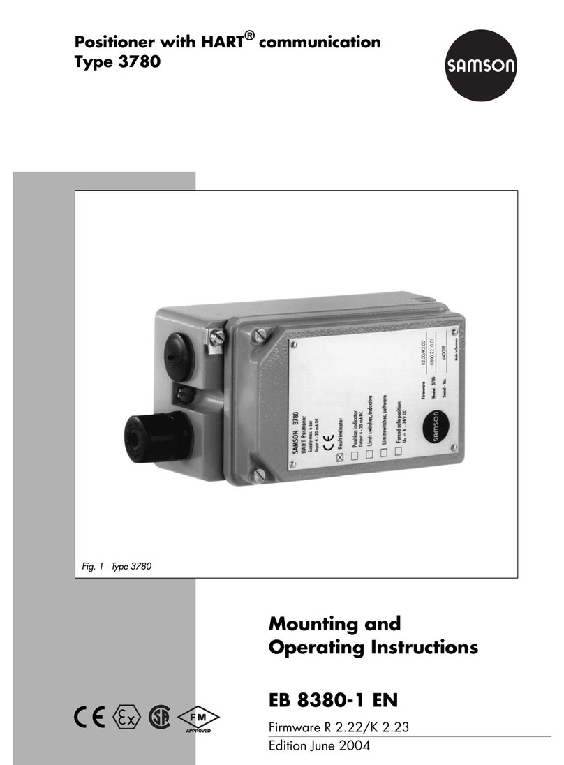
  9. Samson 3780 series Service manual

Samson 3780 series Service manual

Other manuals for 3780 series

2

Other Samson Valve Positioner manuals

Samson 4785 Service manual

Samson

Samson 4785 Service manual

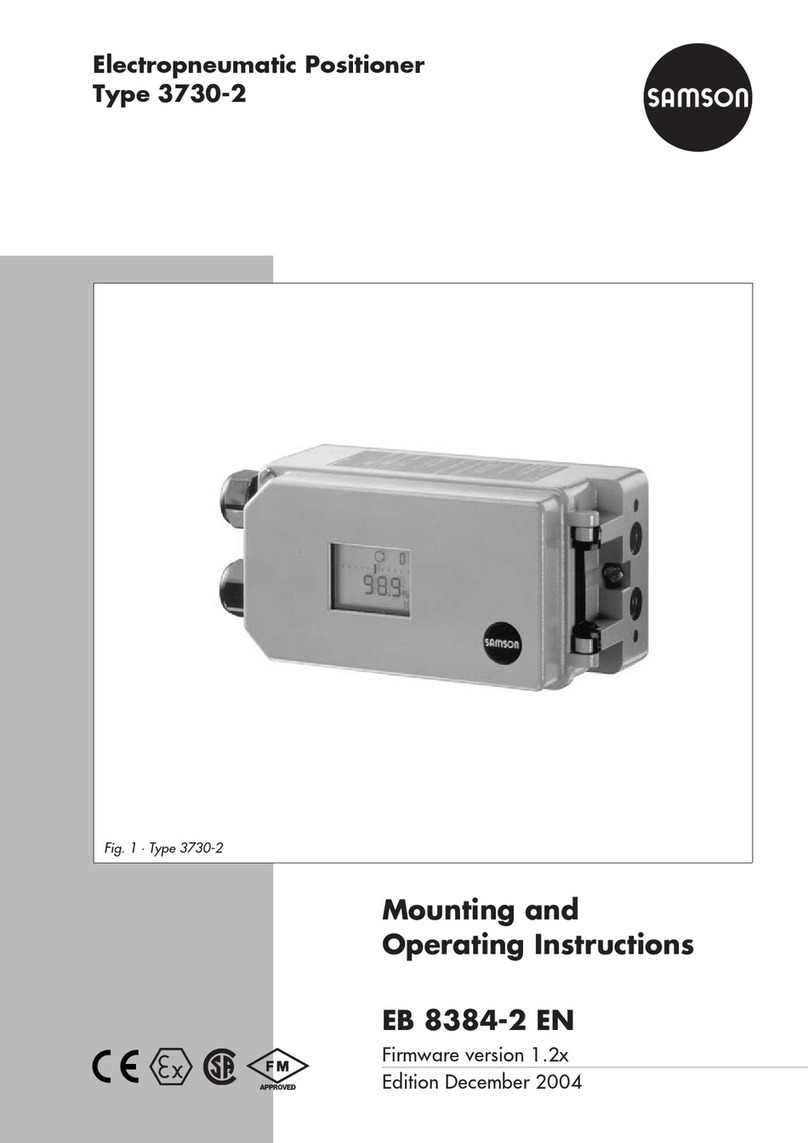
Samson 3730 Series Service manual

Samson

Samson 3730 Series Service manual

Samson 4763 Service manual

Samson

Samson 4763 Service manual

Samson 3760 Service manual

Samson

Samson 3760 Service manual

Samson 4763 Service manual

Samson

Samson 4763 Service manual

Samson TROVIS 3793 User manual

Samson

Samson TROVIS 3793 User manual

Samson 3725 series Service manual

Samson

Samson 3725 series Service manual

Samson 3780 series Service manual

Samson

Samson 3780 series Service manual

Samson TROVIS 3793 User manual

Samson

Samson TROVIS 3793 User manual

Samson 3730 Series Service manual

Samson

Samson 3730 Series Service manual

Samson 3730-4 Service manual

Samson

Samson 3730-4 Service manual

Samson TROVIS 3730-3 Service manual

Samson

Samson TROVIS 3730-3 Service manual

Samson 4763 Service manual

Samson

Samson 4763 Service manual

Samson 3730-4 Instruction sheet

Samson

Samson 3730-4 Instruction sheet

Samson 3761 Service manual

Samson

Samson 3761 Service manual

Samson 3780 series Service manual

Samson

Samson 3780 series Service manual

Samson 3730-3 ESD Service manual

Samson

Samson 3730-3 ESD Service manual

Samson 373 Series User manual

Samson

Samson 373 Series User manual

Samson TROVIS 3730-1 Service manual

Samson

Samson TROVIS 3730-1 Service manual

Samson 3730-0 Service manual

Samson

Samson 3730-0 Service manual

Samson 3730 Series Service manual

Samson

Samson 3730 Series Service manual

Samson TROVIS SAFE 3730 Series User manual

Samson

Samson TROVIS SAFE 3730 Series User manual

Samson 3730-0 Service manual

Samson

Samson 3730-0 Service manual

Samson Type 3766 Service manual

Samson

Samson Type 3766 Service manual

Popular Valve Positioner manuals by other brands

HALDER 23111.0016 Short instruction manual

HALDER

HALDER 23111.0016 Short instruction manual

Parker 404XE Series product manual

Parker

Parker 404XE Series product manual

Ytc TMP-3000 product manual

Ytc

Ytc TMP-3000 product manual

PI M-605 Series user manual

PI

PI M-605 Series user manual

Pepperl+Fuchs PXV100AS-F200-SSI-V19 manual

Pepperl+Fuchs

Pepperl+Fuchs PXV100AS-F200-SSI-V19 manual

RTK RE 3442 Series Installation and operating instructions

RTK

RTK RE 3442 Series Installation and operating instructions

CVS Controls 1200 instruction manual

CVS Controls

CVS Controls 1200 instruction manual

Westlock Quantum 2800 Installation & operating instructions

Westlock

Westlock Quantum 2800 Installation & operating instructions

ESCO Technologies ETS LINDGREN 2302-001 user manual

ESCO Technologies

ESCO Technologies ETS LINDGREN 2302-001 user manual

Parker MX80L series product manual

Parker

Parker MX80L series product manual

SMC Networks IP8000 manual

SMC Networks

SMC Networks IP8000 manual

Siemens SIPART PS2 operating instructions

Siemens

Siemens SIPART PS2 operating instructions

Burkert 8694 operating instructions

Burkert

Burkert 8694 operating instructions

iXBlue POSIDONIA II Technical description

iXBlue

iXBlue POSIDONIA II Technical description

Flowserve Logix 3200IQ Replacement instructions

Flowserve

Flowserve Logix 3200IQ Replacement instructions

Lang LHT500 Assembly instruction

Lang

Lang LHT500 Assembly instruction

Spirax Sarco SP7-21 quick start guide

Spirax Sarco

Spirax Sarco SP7-21 quick start guide

Topworx PD200 quick start guide

Topworx

Topworx PD200 quick start guide

manuals.online logo
manuals.online logoBrands
  • About & Mission
  • Contact us
  • Privacy Policy
  • Terms and Conditions

Copyright 2025 Manuals.Online. All Rights Reserved.

Positioner with HART® communication
Type 3780
Mounting and
Operating nstructions
EB 8380-1 EN
Firmware R 2.22/K 2.23
Edition June 2004
Fig. 1 ⋅Type 3780
All manuals and user guides at all-guides.com
all-guides.com
Contents Page
1. Design and principle of operation . . . . . . . . . . . . . . . . . . . . . . 10
1.1 Options . . . . . . . . . . . . . . . . . . . . . . . . . . . . . . . . . . . 10
1.2 Communication . . . . . . . . . . . . . . . . . . . . . . . . . . . . . . . 11
2. Attachment to the control valve . . . . . . . . . . . . . . . . . . . . . . . 13
2.1 Direct attachment to Type 3277 Actuator . . . . . . . . . . . . . . . . . . . 14
2.2 Attachment according to I C 60534-6 . . . . . . . . . . . . . . . . . . . . 18
2.2.1 Mounting sequence . . . . . . . . . . . . . . . . . . . . . . . . . . . . . 18
2.2.2 Presetting the valve travel . . . . . . . . . . . . . . . . . . . . . . . . . . . 20
2.3 Attachment to rotary valves . . . . . . . . . . . . . . . . . . . . . . . . . . 22
2.3.1 Mounting the cam follower roll lever . . . . . . . . . . . . . . . . . . . . . 22
2.3.2 Mounting the intermediate piece . . . . . . . . . . . . . . . . . . . . . . . 22
2.3.3 Aligning and mounting the cam disk . . . . . . . . . . . . . . . . . . . . . 24
2.3.4 Reversing amplifiers for double-acting actuators . . . . . . . . . . . . . . . . 26
2.4 Fail-safe action of the actuator . . . . . . . . . . . . . . . . . . . . . . . . 26
3. Connections . . . . . . . . . . . . . . . . . . . . . . . . . . . . . . . . . 28
3.1 Pneumatic connections . . . . . . . . . . . . . . . . . . . . . . . . . . . . 28
3.1.1 Pressure gauge . . . . . . . . . . . . . . . . . . . . . . . . . . . . . . . 28
3.1.2 Supply air pressure . . . . . . . . . . . . . . . . . . . . . . . . . . . . . 29
3.2 lectrical connections . . . . . . . . . . . . . . . . . . . . . . . . . . . . 29
3.2.1 Switching amplifiers . . . . . . . . . . . . . . . . . . . . . . . . . . . . . 31
3.2.2 stablishing communication . . . . . . . . . . . . . . . . . . . . . . . . . 32
4. Operation . . . . . . . . . . . . . . . . . . . . . . . . . . . . . . . . . . 34
4.1 Write protection . . . . . . . . . . . . . . . . . . . . . . . . . . . . . . . 34
4.2 Activate/deactivate forced venting function . . . . . . . . . . . . . . . . . . 34
4.3 Default setting . . . . . . . . . . . . . . . . . . . . . . . . . . . . . . . . 35
4.3.1 Adjusting mechanical zero point . . . . . . . . . . . . . . . . . . . . . . . 35
4.3.2 Initialization . . . . . . . . . . . . . . . . . . . . . . . . . . . . . . . . . 35
4.4 Adjusting inductive limit switches . . . . . . . . . . . . . . . . . . . . . . . 37
5. Maintenance . . . . . . . . . . . . . . . . . . . . . . . . . . . . . . . . 38
. Servicing explosion-protected versions . . . . . . . . . . . . . . . . . . . . 38
7. Summary of parameters . . . . . . . . . . . . . . . . . . . . . . . . . . . 39
8. List of parameters . . . . . . . . . . . . . . . . . . . . . . . . . . . . . . 42
9. Error messages and diagnostics . . . . . . . . . . . . . . . . . . . . . . . 53
9.1 Information/alerts . . . . . . . . . . . . . . . . . . . . . . . . . . . . . . 54
9.2 rror messages . . . . . . . . . . . . . . . . . . . . . . . . . . . . . . . 56
Contents
2EB 8380-1 EN
All manuals and user guides at all-guides.com
9.3 rror messages during initialization without abortion . . . . . . . . . . . . 59
9.4 rror messages during initialization with abortion . . . . . . . . . . . . . . 60
Dimensional diagram . . . . . . . . . . . . . . . . . . . . . . . . . . . 62
Type examination certificates . . . . . . . . . . . . . . . . . . . . . . . 63
Safety instructions
Assembly, commissioning and operation of the device may only
be performed by trained and e perienced personnel familiar
with this product. According to these mounting and operating in-
structions, trained personnel is referred to persons who are able
to judge the work they are assigned to and recognize possible
dangers due to their specialized training, their knowledge and
e perience as well as their knowledge of the relevant standards.
E plosion-protected versions of this device may only be oper-
ated by personnel who have undergone special training or in-
structions or who are authorized to work on e plosion-protected
devices in hazardous areas. See section 6 for more details.
For devices in type of protection EE nA, the following applies:
live circuits may only be connected, interrupted, and switched
for installation, maintenance or repair purposes.
Devices that have already been used outside of hazardous areas
and are intended for use in hazardous areas in future shall com-
ply with the safety demands placed on serviced devices. Prior to
operation, they shall be tested according to paragraph 26 "Re-
pairing e plosion-protected devices" of EN 50014:2000 to
meet the safety requirements specified in this standard.
Any hazards which could be caused by the process medium, the
signal pressure and moving parts of the control valve are to be
prevented by means of appropriate measures.
If inadmissible motions or forces are produced in the actuator as
a result of the level of the supply air pressure, this must be re-
stricted by means of a suitable pressure reducing station.
Proper shipping and appropriate storage are assumed.
Note: Devices with the CE mark meet the requirements specified in the
Directive 94/9/EC and the Directive 89/336/EEC.
The Declaration of Conformity is available on request.
EB 8380-1 EN 3
All manuals and user guides at all-guides.com
Modifications of positioner firmware
Modifications of positioner firmware in comparison to previous version
Former New
For more details on the listed parameters, please also refer to the
list of parameters in section 8.
Positioner R 1.41 R 2.01
Parameters:
Operating direction Direction of action
The reference variable (w) is not assigned to the output signal
pressure (y) anymore, but to the travel/angle of rotation (x).
>> increasing/increasing, valve opens with increasing reference
variable.
<> increasing/decreasing, valve closes with increasing reference
variable.
Minimum transit time
filling/venting
Minimum transit time open/closed
The measured time is not referenced to filling/venting the
actuator, but to the opening and closing the valve.
Required transit time
filling/venting
Required transit time open/closed
The actuating time is not referenced to filling/venting the actuator,
but to the opening and closing the valve.
Cycle time factor
K_IS
Omitted
Initialization For version R2.02 or higher, an alarm message is generated for
deviations larger than 10 % when the type of initialization is
maximum range. It is for the user to decide if he wants to tolerate
the deviation.
Tolerated overshoot If overshoot and dead band are exceeded by the negative
deviation value, the pulse is adapted.
Text field Free space for storing information text in the field device.
4EB 8380-1 EN
All manuals and user guides at all-guides.com
Modifications of positioner firmware
Former New
Positioner 2.02 R 2.11
Parameters:
Minimum pulse
filling/venting
The minimum pulses for filling and venting are determined for
the travel ranges 0 to 20 %, 20 to 80 % and 80 to 100 %. The
minimum pulses are no longer determined during initialization.
Proportional-action
coefficient
KP_Y1 and KP_Y2
These factors are adapted to the actuator type selected and to
the transit times measured.
Gain factor
KD
Initialization "Air leakage of pneumatic system" is displayed as alarm
message, but does not cause abortion of initialization anymore.
Upon initialization in the "nominal range", the positioner
assumes only 100 % travel (no overtravel).
"Wrong selection of rated travel/angle of rotation or
transmission" is displayed as alarm message, but does not cause
abortion of initialization anymore.
Positioner 2.11 R 2.21
Type of actuator Change over type of actuator from "linear actuator" to "rotary
actuator"
Initialization type .................Based on maximum range
Transmission code................S90
Nominal angle.....................90°
nd position when w <..........1 %
nd position when w >..........99 %
Rotational angle range start .. 0°
Rotational angle range end ... 90°
Change over type of actuator from "rotary actuator" to "linear
actuator"
Attachment .........................Integral...............................Acc. to NAMUR
Initialization type .................Based on nominal range.......Based on nominal range
Mounting position................Arrow towards actuator........Arrow away from actuator
Transmission code................D1......................................
Pin position.......................... ........................................A
Rated travel .........................15 mm ................................15 mm
nd position when w <..........1 % .....................................1 %
nd position when w >..........125 %.................................125 %
Travel range start..................0 mm ..................................0 mm
Travel range end ..................15 mm ................................15 mm
Length of lever...................... ........................................42 mm
EB 8380-1 EN
All manuals and user guides at all-guides.com
Modifications of positioner firmware
End position when w
</>
Changing the type of initialization from "maximum range" to
"nominal range" causes:
nd position at < 1 % nd position at > 125 %
Changing the type of initialization from "nominal range" to
"maximum range" causes:
nd position at < 1 % nd position at > 99 %
Extended
valve diagnostics
Supports TROVIS- XP RT in version 1.0 or higher
Required transit time
open/closed
The adjustment range for the required transit times has been
limited to 75 s. Safe functioning can only be guaranteed up to
this limit value.
Initialization During initialization, the minimum control pulses for the range
20 % to 80 % of the range of the manipulated variable are
determined and saved in the PROM.
Proportional-action
coefficient
KP_Y1 and KP_Y2
These factors are adapted to the type of actuator chosen and the
transit times measured.
Positioner 2.21 R 2.22
Correction in "manual" operating mode and direction of action
Correction in zero calibration started via communication
Communication K 1.00 K 2.01
Characteristic type Free space for entering information on the description of the
user-defined characteristic saved in the device. Can be stored in
the field device.
For version K 2.02 or higher, when selecting [equal percentage]
or [equal percentage reverse], the description text in parameter
characteristic type of the device is automatically set to the
selection made.
Communication K 2.02 K 2.11
Supports all functions of R 2.11
Type of initialization For K 2.11 or higher, the default value is "maximum range"
End position when w > For K 2.11 or higher, the default value is 99 %
6EB 8380-1 EN
All manuals and user guides at all-guides.com
all-guides.com
Positioner versions
Former New
Communication
K 2.13 K 2.21
Supports all functions of R 2.21 as well as TROVIS- XP RT in
version 1.0 or higher
Communication
K 2.21 K 2.22
Supports all functions of R 2.21 as well as TROVIS-VI Win
version 2.0 or higher
New for model index 3780-x...x. 01 or higher: Write protection switch
If this option is activated using the switch, the positioner settings cannot be written over by
HART® communication. See section 4.1 for more details on the write protection switch.
Model index 3780-x...x. 03 or higher are suitable for the extended valve diagnosis using
the TROVIS- XP RT software.
Positioner versions
Model 3780 - XXXXX
xplosion
protection
Without
x II 2 G x iA IIC T6 as per AT X
CSA/FM
x II 3 G x nA II T6 as per AT X
0
1
3
8
Additional
accessories
Limit switches Without
2 inductive
2 software
0
2
3
Forced venting Without
With
0
1
Position transmitter Without
4...20 mA
0
1
Pneumatic
connections
NPT 1/4-18
ISO 228/1-G 1/4
1
2
EB 8380-1 EN 7
All manuals and user guides at all-guides.com
Positioner
Rated travel, adjustable Direct attachm. 5 to 30mm
Attachment acc. to I C 60534-6 (NAMUR), 5 to 255 mm or 30 to 120° C
Reference variable Two-wire connection, signal range 4 to 20 mA, span 4 to 16 mA
Min. current = 3.6 mA, load ≤10.8 V (corresponding to 540
Ω at 20 mA),
static destruction limit 500 mA
Supply Supply air from 1.4 to 6 bar (20 to 90 psi)
Signal pressure (output) 0 bar to pressure of supply air
Characteristic, adjustable Linear, equal percentage, reverse equal percentage, user-programmable
Deviation from characteristic
≤1 %
Dead band Adjustable from 0.1 to 10 %, default 0.5 %
Resolution ≤0.05 %
Transit time to travel Up to 75 s, separately adjustable for exhaust and supply air
Moving direction Reversible, adjustment via software
Air consumption Independent of supply air <90l

/h
Air delivery Actuator filled: for
Δp = 6 bar 9.3 m

/h, for Δp = 1.4 bar 3.5 m

/h
Actuator vented: for
Δp = 6 bar 15.5 m

/h, for Δp = 1.4 bar 5.8 m

/h
Perm. ambient temperature − 20 to 80 °C, with metal cable gland
− 40 to 80 °C
Devices with position transmitter only
− 20 to 80 °C
For explosion-protected devices, see type examination certificate in appendix
ffects Temperature: ≤0.15 %/10 K, supply: none, vibrations: none up to 250 Hz and 4 g
xplosion protection x ia IIC T6, see type examination certificate
Degree of protection IP 65 by using the filter check valve included
lectromagnetic
compatibility
Requirements stipulated in N 61000-6-2, N 61000-6-3 as well as NAMUR
Recommendation 21 have been met
lectrical connections 1 cable gland M20x1.5, black plastic;
other threaded hole M20x1.5 available
Fault alarm output For connection to switching amplifier acc. to N 60947-4-6, static destruction limit 16 V
Forced venting
(model index .03 or
higher)
Activated/deactivated by a switch inside case
Input: 6...24 V DC, R

approx. 6 kΩ, at 24 V DC (depending on voltage), switching point
for "1" signal at
≥ 3 V, signal "0" only at 0 V, K

value 0.17; static destruction limit 45 V
Technical data
8EB 8380-1 EN
All manuals and user guides at all-guides.com
Communication
Hardware requirements SAMSONs TROVIS-VI W Operator Interface (see Data Sheet T 6661 N) or handheld
communicator, e.g. Type 275 by Rosemount
Integration of other operator interfaces, e.g. DTM, are available
Data transmission HART
®
Field Communication Protocol
Impedance in HART
®
frequency range: receive: 350 to 450
Ω; send: approx. 115Ω
Accessory equipment
Inductive limit switches Two Type SJ 2 SN Prox. Switches for connection to switching amplifier acc. to N 60947-5-6
Software limit switches Two configurable limit values for connection to switching amplifier acc. to N 60947-5-6
Switching hysteresis 1%, static destruction limit 16 V
Analog position
transmitter
Two-wire transmitter, output 4 to 20 mA
Supply: terminal voltage 12 to 35 V DC, static destruction limit 40 V
Direction of action reversible, characteristic linear, operating range: 10 % to + 114 %
DC current signal ripple content: 0.6 % at 28 Hz/I C 381 T1
Resolution≤0.05 %
HF influence <2 % with f= 50 to 80 Mhz
Influence aux. supply: none; temperature influence: same as positioner
Materials (numbers according to DIN)
Case Die-cast aluminum, chromed and plastic-coated
xternal parts: stainless steel 1.4571 and 1.4301
Weight Approx. 1.3 kg
Versions
EB 8380-1 EN 9
All manuals and user guides at all-guides.com
1. Design and principle of operation
The positioner essentially consists of an in-
ductive, non-contact travel measuring sys-
tem and an electrically controlled valve
block comprising two 2/2-way on-off
valves and an electronic unit. This unit con-
tains two microcontrollers for processing the
control algorithm and managing the com-
munication.
Whenever a deviation between the actual
valve travel (actual value) and the reference
variable (set point) occurs, the microcontrol-
ler produces binary pulse-pause modulated
signals to control the two 2/2-way on-off
valves, each of which is assigned an am-
plifier. One of these valves controls the ex-
haust air, and the other one controls the sup-
ply air.
The supply air valve (3) switches the supply
air (7, supply air pressure 1.4 to 6 bar) to
the actuator (filling). The exhaust air valve
(4) controls the air exhausted from the actu-
ator to the atmosphere (venting). These on-
off valves can either have the switching
states - permanently open, permanently
closed - or generate single pulses of chang-
ing widths. With the two valves being con-
trolled, the plug stem moves to a position
corresponding to the reference variable. If
there is no system deviation, both the supply
air and the exhaust air valve are closed.
As a standard feature, the positioner is
equipped with a fault alarm output (binary
output according to N 60947-5-6) used to
signalize a fault to the control room.
Activating the write protection switch lo-
cated in the hinged cover prevents the posi-
tioner settings from being overwritten by the
HART® protocol.
Forced venting function
The positioner is controlled via a 6 to
24 V signal, causing the signal pressure
to be applied to the actuator. If this volt-
age signal decreases, the signal pressure is
shut off and the actuator is vented. The
springs contained in the actuator move the
valve to its fail-safe position.
The forced venting function is installed in all
positioners from model index .03 or higher.
The function can be activated or deacti-
vated by a switch. See section 4.2 (page
34) for more details.
1.1 Options
As a supplement to the standard positioner
version, there are several additional options
to extend the positioner functions.
Limit switches
To signalize the valves end positions in fail-
safe circuits, either two software limit swit-
ches or two proximity switches can be used.
Position transmitter
The position transmitter is an intrinsically
safe 2-wire transmitter controlled by the
microcontroller of the positioner. It serves to
assign the valve position with the 4 to 20
mA output signal. The position transmitter
signalizes both end positions, "valve closed"
or "valve fully open", as well as all inter-
mediate positions. Since the valve positions
are signalized to the positioner inde-
pendently of the input signal (minimum
current must be observed), the position
transmitter is a suitable option for checking
the current valve position.
10 EB 8380-1 EN
Design and principle of operation
All manuals and user guides at all-guides.com