Metso NE Series Operating and maintenance manual

7 NE 72 en • 2/2020
Positioners
Series NE
Installation, Maintenance and
Operating Instructions

27 NE 72 en
READ THESE INSTRUCTIONS FIRST!
These instructions provide information about safe handling and operation of the positioner.
If you require additional assistance, please contact the manufacturer or manufacturer's representative.
Addresses and phone numbers are printed on the back cover.
SAVE THESE INSTRUCTIONS!
Subject to change without notice.
All trademarks are property of their respective owners.
Table of Contents
1 INTRODUCTION ...................................................3
1.1 General view........................................................... 3
1.2 Principle of operation .........................................3
1.3 Marking of positioner ..........................................3
1.4 Technical specifications ..................................... 4
1.5 Recycling and disposal of a rejected
positioner ................................................................ 4
1.6 Safety precautions ............................................... 4
2 MOUNTING ON THE METSO ACTUATOR ............5
2.1 General ..................................................................... 5
2.2 Installing positioner NE700/S1 on
Metso actuators with VDI/VDE 3845
mounting face .......................................................5
2.3 NE_700/700 positioner/limit switch
combination (Obsolete since 2013) ...............5
2.4 Piping of supply air ..............................................5
2.5 Instrument air supply ..........................................8
2.6 Electric connections ............................................8
3 INPUT SIGNAL AND DIRECTIONS OF
OPERATION ..........................................................8
3.1 Changeover piece ................................................8
3.2 Cam plate ................................................................8
4 PRELIMINARY ACTIONS FOR
THE ADJUSTMENT ...............................................9
4.1 Position of the changeover piece ...................9
4.2 Pilot valve ................................................................9
4.3 Setting the internal feed-back spring ...........9
4.4 Position of the cam plate ...................................9
5 BASIC ADJUSTMENT ......................................... 10
6a
0ADJUSTMENT ................................................10
7 SPLIT-RANGE ADJUSTMENT .............................11
8 MAINTENANCE ..................................................11
8.1 Supply air filter ................................................... 11
8.2 Pilot valve ............................................................. 11
8.3 Replacement of the diaphragms .................. 12
8.4 Force coil-nozzle assembly ............................ 12
8.5 Changing the restriction assembly ............. 12
9 TROUBLESHOOTING .........................................12
9.1 Electrical defects ................................................ 12
9.2 Mechanical defects ........................................... 13
10 OPTIONS ............................................................ 13
10.1 NE700/R dust-proof construction (IP65).... 13
10.2 NE700/A with pressure gauges .....................13
11 TOOLS ................................................................ 13
12 ORDERING SPARE PARTS ................................. 13
13 DRAWINGS AND PARTS LISTS .......................... 14
13.1 Exploded view and parts list ..........................14
13.2 Mounting parts for B1C6-502 and
B1J8-322 actuators (S1) ....................................16
13.3 Mounting parts for Quadra-Powr®
actuators (S1) .......................................................17
13.4 Mounting parts for B1C6-20 and
B1J8-20 actuators (S2) ......................................18
13.5 Mounting parts for B1C25-502 and
B1J25-322 actuators (S2) ..................................19
14 TYPE CODE ........................................................ 20

7 NE 72 en 3
1 INTRODUCTION
1.1 General view
The NE700 electro-pneumatic posiotioner is used for posi-
tioning double or single acting actuator.
1.2 Principle of operation
Operation is based on the torque balance. Force coil (152)
located in the field of the permanent magnet (168) creates
a torque proportional to the signal current on the balance
beam (164).
The feed-back spring (41) causes a counter-torque propor-
tional to the actuator position; this position is transmited
via the actuator shaft, the coupling (52), the feed-back shaft
(26), the cam plate (29) and the lever (33) as a relative dis-
placement to the lower end of the feed-back spring (41).
The nozzle (166) senses the torque balance on the beam
(164). When the input signal increases, the balance beam
(164) approaches the nozzle (166) and the nozzle pressure
rises. This causes the diaphragm piston (8), the beam (5)
and the spool (44.2) to move downward. The pilot valve (44)
distributes supply air (S) to the upper side of the actuator
piston via channel C2, and from the lower side via channel
C1 through the pilot valve (44) to the exhaust port. The
actuator piston moves until the balance beam is in equilib-
rium. At this point the actuator is exactly in the position
required by the input signal.
The spring (40) causes a negative feed-back between the
first amplification stage (nozzle 166 and restriction 24) and
the second (pilot valve assembly 44). By changing the lower
fastening point for the spring (40) on the balance beam
(164), the dynamics of the positioner can be adapted to suit
the actuator size.
The zero adjustment (61) is mechanical and the range
adjustment (35.6) is electrical.
The differential diaphragms effectively offset the effect of
fluctuations in the supply pressure.
Parts list for Figure 1:
Item Part
5Beam
8Diaphragmpiston
24 Restriction
26 Feed-back shaft
29 Camplate
33 Lever
35.6 Range adjustment
40 Internal feed-back spring
41 Feed-back spring
44.1 Pilot valve body
44.2 Pilot valve spool
46 Changeover piece
52 Coupling
61 Zero adjustment
152 Force coil
164 Balance beam
166 Nozzle
168 Permanent magnet
1.3 Marking of positioner
The positioner has an adhesive ID plate, see Fig. 2.
The ID plate contains the following information (from top to
bottom):
Full type designation of the positioner
Input signal
Input resistance
Max. supply pressure
Enclosure class
Ambient temperature range
Manufacturing series number
An additional plate, Fig. 3, has markings:
Filter regulator (-K)
Temperature range
Conduit entry (-L, -I or -NJ)
Fig. 1 Schematic diagram
Fig. 2 ID plate
Fig. 3 Additional plate

47 NE 72 en
1.4 Technical specifications
Input signal (direct current) 4–20 mA, 0–20 mA
Split ranges 4–12 mA
12–20 mA
Input resistance max. 190 Ω
Turning angle of feed-back shaft max. 90°
Relation between turning angle
and signal (standard model) linear
Supply pressure ps 1.4–8 bar
(21–115 psi)
Effect of supply pressure < 0.2 % / 0.1 bar
(< 0.14 % / 1 psi)
Ambient temperature (standard model) -25° to +85 °C
(-13° to +185 °F)
Effect of temperature < 0.05 % / °C
(< 0.025 % / °F)
Performance with 12 % friction
loaded double-acting piston actuator
-dead band < 0.3 %
- hysteresis < 0.7 %
-linearity < 2 %
Effect of vibration (1.5 g, 5-100 Hz)< 1 %
Enclosure class IP 54
Weight approx. 2.2 kg (4.8 lb)
Construction materials:
-case anodized Al alloy
-cover polycarbonate
-internal parts stainless steel,
aluminium alloy and
stainless spring steel
- diaphragms and seals nitrile rubber
(standard model)
1.5 Recycling and disposal of a rejected
positioner
Most positioner parts can be recycled if sorted according to
material. Most parts have material marking. A material list is
supplied with the positioner. In addition, separate recycling
and disposal instructions are available from the manufac-
turer. A positioner can also be returned to the manufacturer
for recycling and disposal against a fee.
1.6 Safety precautions
Table 1 Pilot valve alternatives
Positioner
type
Actuator
stroke volume
dm3(litres)
Air
consumption
nm3/h / scfm *)
Max. delivery
nm3/h / scfm *)
NE724 1.0–8.0 0.9 / 0.5 12 / 7
NE726 8.0–30.0 1.2 / 0.7 18 / 10.4
NE727 > 30 2.1 / 1.2 32 / 18.6
*) supply pressure 4 bar / 60 psi
CAUTION:
Do not exceed the positioner performance limitations!
Exceeding the limitations marked on the positioner may
cause damage to the posioner, actuator and valve.
Damage or personal injury may result.
CAUTION:
Do not dismantle a pressurized positioner!
Dismantling a pressurized positioner will result in uncon-
trolled pressure release. Always isolate the relevant part of
the pipeline, release the pressure from the positioner and
the piping.
Failure to do this may result in damage or personal injury.
CAUTION:
Beware of the parts with live voltage!
A voltage, which is normally not dangerous, is supplied to
the positioner. Avoid touching live parts and bare wires
and short circuiting live parts and the housing.
CAUTION:
Beware of the moving parts when positioner is oper-
ated!
7 NE 72 en 5
2 MOUNTING ON THE METSO ACTUATOR
2.1 General
When the positioner is supplied together with the valve and
actuator, the tubes are mounted and the positioner adjusted in
accordance with the customer's specifications.
When the positioner is ordered separately, the mounting parts
for the assembly must be ordered at the same time.
Example order: Positioner alone (BC12)-Z-NE724.
The positioner is equipped with VDI/VDE 3845 (S1) mount-
ing face. This mounting face requires a shaft with the H cou-
pling.
Old Metso Automation style mounting face code S2 is no
more available.
For mounting parts for Metso actuators, see Sections 13.2 -
13.3.
2.2 Installing positioner NE700/S1 on
Metso actuators with VDI/VDE 3845
mounting face
1. The actuator piston must be in the up position (in spring-
return actuators as determined by the spring).
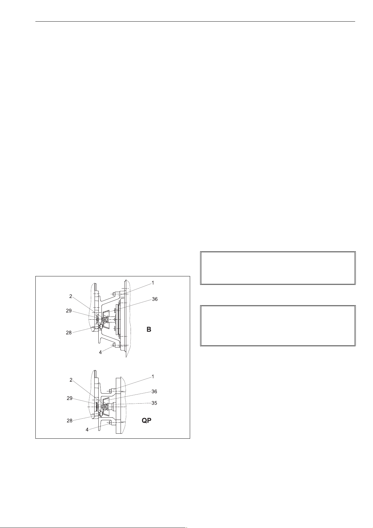
2. Install the pointer (only B_U) parallel with the valve clo-
sure member and fasten the draught piece (2) with a
screw (29) to the pointer cover (B_U) or to the coupling
(QP), as shown in Fig. 5. Secure the draught piece fasten-
ing screw with a sealant (e.g. Loctite) and tighten it
properly.
3. Fasten the mounting bracket (1) to the positioner.
4. Fasten the mounting bracket (1) to the actuator.
2.3 NE_700/700 positioner/limit switch
combination (Obsolete since 2013)
The bottom of the limit switch acts also as the cover for the
positioner. Remove the limit switch before the adjustment
of the positioner.
1. Loosen the cover screws. Note the position of the shaft
relative to the positioner when removing the limit switch.
2. When the adjustment of the positioner is done, operate
the actuator until the valve is in the closed or open posi-
tion.
3. Note the position of the actuator and valve when
mounting the limit switch on the actuator. Make sure
that the position of the shaft is unchanged relative to
the positioner.
4. Place the limit switch on the positioner so that the
shafts are correctly engaged.
5. Fasten the cover screws.
6. Check the adjustment of the limit switch. See the
instruction manual of the limit switch for details.
2.4 Piping of supply air
Table 2 provides the recommended pilot valve and tube
sizes in accordance with the actuator sizes. Tube sizes are
minimum values allowed.
Connect air supply to S (1/4 NPT).
Connect C1 and C2 (1/4 NPT) to the actuator according to
Fig. 6.
See also Chapter 3.
For pipe threads are liquid sealants, e.g. Loctite, recom-
mended.
Fig. 4 Installing on a Metso actuator (S1)
NOTE:
A single action connection alone is permitted for position-
ers mounted on the spring actuator!
Place a plug in connection C1 or C2. See Figure 6.
NOTE:
Exessive sealant may cause faulty operation of the posi-
tioner.
Sealing tape is not recommended.
Ensure the cleaness of the air piping.

67 NE 72 en
Table 2 Piping and operating times
Actuator
NPT
Piping Operating time / stroke (s)
pilot valve
Plastic/Cu/SS (mm) Plastic/Cu/SS (")
B1C Stroke vol.
dm3/in36/4 10/8 12/10 1/4 3/8 1/2 ø4LC ø4 ø6 ø6 HC
60.3/201/4x x 1 1
9 0.6/37 1/4 x x 1.5 1.5
11 1.1/67 3/8 x x 2 2
13 2.3/140 3/8 x x 4
17
20
4.3/262
5.4/330
1/2 x
x
x
x
7
8.5
(6)
(5.5)
25
32
10.5/640
21/1282
1/2
3/4
x
x
(x)
(x)
x
x
(x)
(x)
10
17
(8.5)
(16)
40
50
43/2624
84/5130
3/4
1
x
x
(x)
(x)
x
x
(33)
(60)
31
57
502 195/11900 1 x x
B1J
B1JA
Stroke vol.
dm3/in3NPT 6/4 10/8 12/10 1/4 3/8 1/2 ø4LC ø4 ø6 ø6 HC
6 0.47 / 28.7 1/4 x x 1 1
8
10
0.9/55
1.8/111
3/8 x
x
x
x
1.5/3 1.5/3
2.5/5.5
12
16
3.6/225
6.7 / 415
1/2 x
x
x
x
4.5/11
8/18
(3.5/6)
(4.5/11)
20
25
13/795
27 / 1642
3/4 x
x
(x)
(x)
x
x
(x)
(x)
8.5/21
17/38
(7.5/19)
(15/33)
32
322
53 / 3231
106 / 6480
1x
x
(x) x
x
(33/74) 30/64
60/130
QP Stroke vol.
dm3/in3NPT 6/4 10/8 12/10 1/4 3/8 1/2 ø4LC ø4 ø6 ø6 HC
1C 0.62/38 3/8 x x 1.5/2 1.5/2 - -
2C 1.08/66 3/8 x x 2/3.5 2/3.5 - -
3C 2.18/133 3/8 x x - 3/5 2/3 -
4C 4.34/265 3/8 x x - 6/10 4/6 -
5C 8.7/531 3/8 x x - - 7/10
6C 17.5/1068 3/4 x x - 12/18 10/15
Times in parenthesis are achieved by changing pilot valve alone or pilot valve and tube size.
Operating times for spring return actuators B1J/B1JA and QP:
against the spring / direction of the spring
Actuator without valve:
ps= 4–5 bar / 58–72 psi
Step of input signal:
pi= 0–100 % and 100–0 %

7 NE 72 en 7
Fig. 5 Positioner actions
NOTE: In positioner NE727 the changeover piece can be used in position R only.
DOUBLE-ACTING
1. Increasing input signal to open valve.
Cam segments:
B/0-100, A/0-50, A/50-100
2. Increasing input signal to close valve.
Cam segments:
A/0-100, B/0-50, B/50-100
NOTE:
Reverse piping for ST actuators.
SINGLE-ACTING
(SPRING TO CLOSE)
3. Increasing input signal to open valve.
Spring to close valve.
Cam segments:
B/0-100, A/0-50, A/50-100
4. Increasing input signal to close valve.
Spring to open valve.
Cam segments:
B/0-100, A/0-50, A/50-100
WARNING:
Valve closes exceptionally counterclockwise.
Unsuitable for Q, R, T5, F and L series valve
NOTE:
Reverse piping for ST actuators. Spring and
piston in the opposite position from shown.
SINGLE-ACTING
(SPRING TO OPEN)
5. Increasing input signal to close valve.
Spring to open valve.
Cam segments:
A/0-100, B/0-50, B/50-100
NOTE:
Reverse piping for ST actuators. Spring and piston in
the opposite position from shown.

87 NE 72 en
2.5 Instrument air supply
The supply air must be clean, dry and oil-free instrument air,
e.g. according to standard ISA S7.3–81. Supply pressure is
1.4–8 bar (20–115 psi).
2.6 Electric connections
The input signal cable is lead trough a PG11 cable gland to
the housing. Connect the conductors to the terninal on the
terminal card, plus (+) and minus (-) accordingly. See Fig. 7.
The wiring schematic is shown in Fig. 8.
3 INPUT SIGNAL AND DIRECTIONS OF
OPERATION
Figure 6 assists in choosing the right segment for the cam
plate (29) and position for the changeover piece (46).
3.1 Changeover piece
The function of connection C1 and C2 can be altered by
turning the changeover piece (46). The diagram D (or R)
shown on the protective plate (48) functions when the sym-
bol D (or R) is visible in the lower lefthand corner of the
changeover piece. D = direct, R = reverse.
External changes in the tubes are not needed. Positioner
NE727 is an exeption (DIA6HC pilot valve). Then the
changeover piece must always be in position R and the
external tubes mounted in accordance with Fig. 6.
3.2 Cam plate
The figures marked on the cam plate (29) are the signal
ranges expressed as percentages, for example 0–100 corre-
sponds to 4–20 mA, or 50–100 to 12–20 mA. See Fig. 9.
The arrows on the cam plate show the direction it must turn
when the input signal is rising in the cam segment in ques-
tion.
The non-rising segments between the rising segments are
roughly 15°–20°.
CAUTION:
Do not exceed the permitted actuator supply air pres-
sure!
NOTE:
The wires should not be led through the operational area
of the feed-back lever (33) and feed-back spring (41).
Fig. 6 Terminal card
feed-back
spring (41)
feed-back
lever (33)
earth
connection range adjustments
terminal
jumper
Fig. 7 Wiring schematic
CAUTION:
Do not dismantle a pressurized positioner!
I
U
1000 W
CCW
CW 220 W 47 mF
Rk=220 W
Fig. 8 Input signal ranges
50 - 100
0 - 100
0 - 50
B
~ 15°
~ 15°
~ 15°
~ 15°
~ 15°
~ 15°
4...12 mA/0...10 mA/10...30 mA
rising signal closes
segment C
segment E
segment D
segment C
segment E
4...12 mA/0...10 mA/10...30 mA
rising signal opens
4...20 mA/0...20 mA/10...50 mA
rising signal opens
4...20 mA/0...20 mA/10...50 mA
rising signal closes
12...20 mA/10...20 mA/30...50 mA
rising signal closes
12...20 mA/10...20 mA/30...50 mA
rising signal opens

7 NE 72 en 9
4 PRELIMINARY ACTIONS FOR THE
ADJUSTMENT
Set the valve's open and closed limits with the actuator lim-
iter screws; see the valve instruction manual. The changeo-
ver piece (46), the cam (29) and the internal feed-back
spring (40) must be in correct positions. Check the pilot
valve size from Table 2.
The adjustment must always be carried out when the sup-
ply pressure has been changed.
Please note that operating of the valve is required during
the adjustment.
4.1 Position of the changeover piece
Choose the position of the changeover piece, D or R, from
Fig. 6 in accordance with the function desired.
Turn the changeover piece (46) when necessary.
Loosen the nuts (49) and remove the protective plate (48).
Pull out the changeover piece (46). Check the O-rings (47,
2 pcs.) and apply silicone grease lightly if needed. Place the
changeover piece (46) and the protective plate (48) in the
case. Tighten the nuts (49) evenly, one after the other.
4.2 Pilot valve
Removal of the pilot valve is unnecessary when the change-
over piece is turned around. For instructions of removal, see
Section 8.2.
4.3 Setting the internal feed-back spring
Select the position for the lower end of the spring (40) from
Table 3 in accordance with the actuator size. The spring set-
ting must be made before the zero adjustment of the posi-
tioner, as it affects the adjustment.
The amplification of the positioner increases as the spring
(40) is moved from position 'a' to position 'e'.
If in the field the valve overshoots, the spring (40) can be
moved to the 'a' direction. If the valve goes into position too
slowly the spring can be moved to the 'e' direction respec-
tively.
In sticker inside the cover (2) has also been shown the posi-
tion for the lower end of the spring (40) in accordance with
the actuator size.
4.4 Position of the cam plate
Choose the side, A or B, and the rising segment of the cam
plate from Fig. 6 in accordance with the function desired.
Move the actuator piston to the end where the input signal
has its lower value. Shut off the supply pressure or move the
pilot spool by deflecting the balance beam (164) gently so
that the piston strokes to the desired limit. The input signal
should be zero or at the lower limit.
Loosen the screw (57), remove the indicator (32), loosen the
screw (31) and the locking wheel (30). Turn the cam plate
(29) to the desired side.
In case of α0adjustment, proceed acc. to Sections 6.1 and
6.2.
Place the roller so that its contact point is 1 mm from the
beginning of the rising segment. Then tighten the locking
wheel (30) and the screw (31).
CAUTION:
Do not dismantle a pressurized positioner!
NOTE:
Check that the changeover piece is mounted correctly:
Symbol D or R is visible in the lower left hand corner.
Fig. 9 Mounting the changeover piece
47 49 48
46
45
44
43
Fig. 10 Setting the internal feed-back spring
Table 3 Setting the internal feed-back spring
Spring (40)
setting Actuator size Cylinder volume
dm3
a B1C 6, 8, B1J 6
QP 1
<0,5
b B1C 9, 11, 12; B1J 8
QP 2 (QP 1 *)
0,5...1
c B1C 13, 16; B1J 10, 12
QP 3 (QP 2 *)
1...4
d B1C 17, 20, 25; B1J 16
QP 4, QP 5 (BJ 8 *)
4...11
e B1C 32, 40; B1J 20, 25
B1C 50, 502; B1J 32, 322
11...50
*) NE729S positioner, (Obsolete since 2013).
NOTE:
Don't move the pilot spool by deflecting the beam (5).
The double diaphragm keeps the beam steadfast in the
position.
ab cde

10 7 NE 72 en
5 BASIC ADJUSTMENT
Basic adjustment is made to rotary and butterfly valves.
Please note the procedures in Chapter 4 before the adjust-
ment.
1. Switch on the supply pressure (S) and the input signal (+/-).
Note the correct polarity.
2. Set the input signal at the closed limit of the valve so that
it is 2 % i.e. 0.3 mA higher or lower than the limit value,
e.g. 4 + 0.3 = 4.3 mA or 20 - 0.3 = 19.7 mA. Turn the zero
adjustment nut (61) with a screwdriver or fingers so that
the actuator comes slowly to the closed limit. The valve
should open slightly with a 4 % change in signal, that is
0.6 mA, e.g. 4 + 0.6 = 4.6 mA or 20 - 0.6 =19.4 mA. See Fig-
ures 12 and 13.
3. Set the input signal to the other limit value. The valve
should be entirely open at 100 %, i.e. 20 mA or 0 %, i.e. 4
mA. The valve should start to operate to closed direc-
tion at 98 %, i.e. 19.7 mA or 4.3 mA.
The range, i.e. turning angle, increases by turning the
range adjustment potentiometer (35.6) counterclock-
wise and de-creases by turning clockwise.
4. The zero and range adjustments affect each other, so
stages 2 and 3 must be repeated a few times.
5. Screw on the pointer (32) into place so that the yellow
line is in the direction of the valve closing member.
Tighten the screw (57).
6α0ADJUSTMENT
α0adjustment is made to segment and ball valves. This
adjustment takes into account the "dead angle" α0of the
ball valve. The entire signal range is then used for effective
valve opening 90°-α0, see Figure 14.
The same adjustment method can be applied to butterfly
valves in papermills for pulp flow control to avoid the dewa-
tering of the pulp near the closed position of the disc.
Table 4 shows the shift on the circumference of the cam
equal to the "dead angle" of the valve, Figure 15, in various
cam segments (C, E, D).
Please note the procedures in Chapter 4 before the adjust-
ment.
1. Mark the shift in question on the edge of the cam, Fig. 15
and Table 4. Dimensions do not have to be measured if
the dead angle can be reliably noticed from position of
the closing member.
2. Lock the cam so that the roller touches the edge of the
cam plate at the mark. Tighten the locking wheel (30)
and the screw (31).
3. Switch on the supply pressure (S) and the input signal
(+/-). Note the correct polarity.
Fig. 11 Basic and
α
0adjustments
Fig. 12 Zero and range adjustments
POSITION %
Rising input signal closes valve Rising input signal opens valve
max 2 %
INPUT SIGNAL %
safety range 2 %
Basic adjustment α0adjustment
UI
SPAN
D
zero adjustment (61)
internal feed-back
spring (40)
feed-back spring (41)
terminal card (35)
range adjustment (35, 6)
Fig. 13 Zero and range adjustments
Fig. 14 Shift on circumference of cam equal to dead angle
α0= dead angle
segment D
segment C
segment E
shift
Roller contact point when
the ball is completely closed

7 NE 72 en 11
4. Set the input signal at the closed limit of the valve so
that it is 2 % i.e. 0.3 mA higher or lower than the limit
value, (e.g. 4 + 0.3 = 4.3 mA or 20 - 0.3 = 19.7 mA). Turn
the zero adjustment nut (61) with a screwdriver or fin-
gers so that the actuator comes slowly to the closed
limit. The valve should open slightly with a 4 % change
in signal, that is 0.6 mA, (e.g. 4 + 0.6 = 4.6 mA or 20 - 0.6
= 19.4 mA). See Figure 13.
5. Set the input signal to the other limit value. The valve
should be entirely open at 100 %, i.e. 20 mA or at 0 %, i.e.
4 mA. The valve should start to operate to closed direc-
tion at 98 %, i.e. 19.7 mA or 4.3 mA.
The range (turning angle) increases by turning the
range adjustment potentiometer (35.6) counterclock-
wise and decreases by turning clockwise.
6. The zero and range adjustments affect each other, so
stages 4 and 5 must be repeated a few times.
7. Screw on the pointer (32) into place so that the yellow
line is in the direction of the valve closing member.
Tighten the screw (57).
7 SPLIT-RANGE ADJUSTMENT
In principle, split range adjustments are made in the same
manner as for a normal signal range. Select a split range, 4–
12 mA or 12–20 mA, from the cam plate. See Figure 9.
8 MAINTENANCE
Regular maintenance is not necessary.
The need for maintenance depends on the quality of the
instrument air. See also Section 2.5.
If there is need for servicing proceed according to the fol-
lowing sections.
8.1 Supply air filter
The supply air filter (50) is located in the supply air connec-
tion (S); the filter can be removed for cleaning.
8.2 Pilot valve
Remove the pilot valve (44) by first loosening the nuts (49),
and then by lifting off the protective plate (48), the change-
over piece (46) and the gasket (45).
The pilot valve spool (44.2) should slip easily in the pilot
valve body (44.1).
If the pilot valve sticks, wash the body and spool with sol-
vent.
See the exploded view for the correct installation position
of the pilot valve. The size code for the pilot valve on the
body, for example DIA 4.0, must be visible on the right side.
Check the condition of the O-rings (43 and 47) and of the
gasket (45). The end of the leaf spring on the beam must be
on top of the pilot valve spool (Figure 13). Make sure that
the end of the beam (5) goes into the spool groove without
sideways deflections. After tightening the nuts (49), check
the beam once again by hand to see that the pilot valve
moves readily.
Table 4 Dead angle in degrees
Valve
size
Valve series
MBV
QMBV
1)
MBV
QMBV
2)
D
3)
T5,
QT5 QXT5 T25,
QT25 QXT25 R,
QR
mm mm Dead angle in degrees
25 1 12.5 - - 23.0 17.5 - - 14
40 1 1/2 11.0 - - 22.0 11.0 - - 11
50 2 9.0 8.0 12.0 22.0 11.0 16.0 7.0 15
65 2 1/2 8.0 - - - - - - 11
80 3 9.0 7.0 11.0 16.0 7.0 15.0 8.0 8
100 4 9.0 7.0 11.0 15.0 7.5 14.5 8.0 7
125 5 11.0 - - - - 11.0 6.0 7
150 6 9.0 7.0 10.5 14.5 8.0 12.0 7
200 8 8.0 6.5 7.5 11.0 6.0 8.5 6
250 10 8.0 6.5 7.0 12.0 8.5 6
300 12 7.0 5.5 5.5 8.5 7.0 5
350 14 5.4 5.5 - 4
400 16 4.5 5.0 8.S(14") 4
450 18 5.0 7.0 (16")
500 20 5.5
600 24 5.0
650 26 6.0
700 28 6.0
750 30 5.5
800 32 -
900 36 4.5
1) Seat supported 2) Trunnion 3) S/G seat
Table 5 Shift caused by dead angle, mm/inch
α0Segment C Segment E Segment D
20° *) 6.1/0.24 8.1/0.31
19° *) 5.8/0.22 7.7/0.30
18° *) 5.5/0.21 7.3/0.28
17° *) 5.2/0.20 6.9/0.27
16° *) 4.9/0.19 6.5/0.25
15° 3.1/0.12 4.6/0.18 6.1/0.24
14° 2.9/0.11 4.3/0.16 5.7/0.22
13° 2.7/0.10 4.0/0.15 5.3/0.20
12° 2.5/0.09 3.7/0.14 4.9/0.19
11° 2.3/0.09 3.4/0.13 4.5/0.17
10° 2.1/0.08 3.1/0.12 4.1/0.16
9° 1.9/0.07 2.8/0.11 3.7/0.14
8° 1.7/0.06 2.5/0.09 3.3/0.12
7° 1.5/0.05 2.2/0.08 2.9/0.11
6° 1.3/0.05 1.9/0.07 2.5/0.09
5° 1.1/0.04 1.6/0.06 2.1/0.08
4° 0.9/0.03 1.3/0.05 1.7/0.06
*) Segment C: α0max. 15°
CAUTION:
Do not dismantle a pressurized positioner!
NOTE:
Ensure the cleanness of the air piping.
NOTE:
The pilot valve body and spool constitute a pair, and must
not be replaced separately.

12 7 NE 72 en
8.3 Replacement of the diaphragms
Remove the spring (40) and loosen the screws (23). Remove
the zero adjustment wheel, the screw (15) and the nut (16).
Replace the diaphragms (13, 14). See Fig. 16. Note the
installation position of the diaphragms convolution.
Check during assembly that the large O-rings (11,12) and
the small ones (18, 19, 20, 21) are in place. Check the condi-
tion of the gasket (55) and secure the nut (16) with Loctite
242. Fasten the zero adjustment wheel (61). Tighten the
cover screws (23) evenly. Check the positioner adjustment
after replacing of diaphragm.
Note: O-rings (11, 12) in the old construction only (manu-
factured before 12/94).
8.4 Force coil-nozzle assembly
Repairing of the force coil-nozzle assembly requires good
knowledge, workmanship and special tools.
It is highly recommended to replace a faulty assembly with
a new one.
Handle and disassemble the coil-nozzle assembly in the
cleanest and most dust-free surroundings possible.
8.4.1 Removing the force coil-nozzle
assembly
1. Disconnect the signal wires from the terminal.
2. Remove the springs (40, 41) and loosen the terminal
screws (36). Remove the terminal card (35).
3. Hold on to the assembly and loosen the screws (38) in
the back wall of the case.
8.4.2 Cleaning the magnet air gap
1. Remove the fastening screw (169) of the magnet (168)
and lift the magnet carefully out of the body. Clean the
magnet air gap with e.g. tape.
2. Place the magnet into the body carefully, making cer-
tain that the moving force coil does not jam in the air
gap. Tighten the screw (169) firmly.
8.4.3 Mounting the force coil-nozzle
assembly
Check the O-ring (39) in the case and the location of the
wire in the body groove. Turn the screws (38) until tight.
Mount the terminal card and the springs. Note the correct
position of the spring (40), see Section 4.3. Check the
adjustment.
8.5 Changing the restriction assembly
Loosen the screw (25) to remove the restriction assembly
(24). A blocked restriction and/or filter can be cleaned if
needed. Replacing the whole assembly is althoug recom-
mended.
9 TROUBLESHOOTING
9.1 Electrical defects
1. The electrical condition of the positioner can be measu-
red in the field in line without shutting down the appara-
tus. There are measurement terminals, see Figs. 7 and 8,
for voltage (U) and current (I) on the terminal card. Pull
out the jumper before taking the measurement. Note the
correct polarity of the meter.
2. Current and voltage measurements can be used to
determine whether the signal line and the electrical
components of the positioner are in order.
Fig. 15 Replacement of diaphragms
NOTE:
gap required
Fig. 16 Restriction assembly (24)
Table 6 Current and voltage measurements
Measurement Possible faults
U (V) I (A)
0 (—) Signal wire polarity wrong
No No Signal wire defect.
Wire not connected to terminal
>4 When
I=20 mA
Coil connection wire or coil winding
defect.
Shunt resistance defective
0 Yes Coil or shunt resistance short circuited
filter
gasket
restriction ø 0.3

7 NE 72 en 13
9.2 Mechanical defects
1. A change in the input signal does not affect the position
of the actuator.
supply pressure too low
diaphragms damaged
pilot valve sticks
seals in the changeover piece leak
tubes between the positioner and the actuator,
change-over piece or position of the cam wrong, see
Fig. 6
actuator and/or valve jammed
restriction assembly blocked, see Fig. 17
2. The actuator goes to the final position with a small
change input signal.
tubes between the positioner and the actuator, the
changeover piece or the position of the cam wrong.
3. Inaccurate positioning
pilot valve dirty
beam (5) pushes the pilot valve spool sideways
diaphragms damaged
dirt in the magnet air gap
actuator torque too low
supply pressure too low
valve torque requirement increased
4. Overshooting or too slow
positioning setting for the internal feed-back spring
wrong
pilot valve dirty or of the wrong size, see Table 2
supply air tube too small or supply air filter dirty
valve sticks
5. Zero point unstable
restriction assembly dirty
inaccurate dead angle α0adjustment
10 OPTIONS
10.1 NE700/R dust-proof construction (IP65)
For extremely dusty environments. The protective cover (3)
behind the standard posioner is replaced with an exhaust
port with a 3/4 NPT filter.
Please note: do not remove the exhaust port.
10.2 NE700/A with pressure gauges
The positioner (manufactured after 9/92) can be equipped
with a pressure gauge block. The block (70) is attached with
tree sef-tapping screws (72). The O-rings (71, 3 pcs.) must
be in position before mounting. Check tightness after
mounting.
For all other constructions see Type code, Chapter 14.
11 TOOLS
In addition to standard general tools, you need the follow-
ing equipment:
calibration device for adjustments
multimeter
12 ORDERING SPARE PARTS
When ordering spare parts, always include the following
information:
type code, sales order number, serial number
number of the parts list, part number, name of the
part and quantity required
This information can be found from the identification plate
or documents.
14 7 NE 72 en
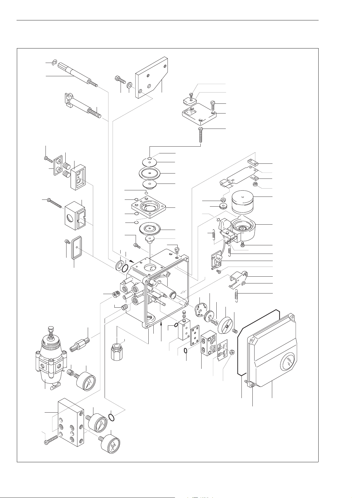
13 DRAWINGS AND PARTS LISTS
13.1 Exploded view and parts list
65
26
26
4
68, 99
64, 101
3, 69, 98
43
4
3
NE700/J_
NE700/S1
NE700/R
NE700/_GN
86
88 87
25
24
23
22
15
76
77
78 79
70
72
73 71
74
54
NE700-K
NE700A
55
10
14
9
17
13
8
20
18
19
21
38
27 28
7
50
62
1
100
43
44
45
47
46
48
49
109
110
2
29
30
31
32
57
58
5
6
59
168
37
169
164 41
35
36
33
34
42
16
61
39
40
105

7 NE 72 en 15
Spare part category 1: Parts for basic maintenance. Delivered as a set
Spare part category 2: Parts for spool valve and cover replacement.
Spare part category 3: Parts for shaft and force coil-nozzle replacement.
Item Qty Description Spare part
category
1 1 Housing assembly
21Coverassembly 2
31Protectivecover
1 Exhaust port (NE700/_G)
41Screw
5 1 Beam assembly
61Plate
72Screw
81Lowerdiaphragmplate 1
9 1 Middle diaphragm plate 1
10 1 Upper diaphragm plate
13 1 Diaphragm 1
14 1 Diaphragm 1
15 1 Screw
16 1 Hexagon nut
17 1 Diaphragm housing assembly
18 1 O-ring 1
19 1 O-ring 1
20 1 O-ring 1
21 1 O-ring 1
22 1 Diaphragm cover
23 1 Screw
24 1 Restriction assembly 1
25 1 Screw
26 1 Shaft assembly 3
27 1 Washer
28 1 O-ring 1
29 1 Cam plate
30 1 Locking wheel
31 1 Screw
32 1 Pointer
33 1 Lever arm assembly
34 1 Retaining ring 1
35 1 Terminal card assembly 3
36 2 Screw
37 1 Force coil-nozzle assembly 3
38 2 Screw
39 1 O-ring 1
40 1 Spring 1
41 1 Spring 1
Item Qty Description Spare part
category
42 1 Spring
43 1 O-ring 1
44 1 Pilot valve assembly 2
45 1 Gasket 1
46 1 Changeover piece
47 2 O-ring 1
48 1 Protective plate
49 2 Hexagon nut
50 1 Filter
53 3 Connector
54 1 Adapter
55 1 Gasket 1
57 1 Grub screw
58 1 Upper support plate
59 2 Barrel nut
61 1 Zero adjustment nut
62 1 Hexagon socket plug
64 1 Body
65 1 Lock ring
68 2 Spring
69 2 Guide
70 1 Pressure gauge block
71 3 O-ring
72 3 Screw
73 1 Pressure gauge
74 2 (1) Pressure gauge
76 1 Double fitting
77 1 Filter regulator
78 1 Reduction fitting
79 1 Pressure gauge
98 2 Screw
99 2 Spring plate
100 1 Additional plate
101 2 O-ring
102 1 Plug
105 1 ID plate
109 1 Seal
110 4 Screw
*) Only in positioners manufactured before 12/94

16 7 NE 72 en
13.2 Mounting parts for B1C6-502 and
B1J8-322 actuators (S1)
Item Qty Description
1 1 Mounting bracket
21Draughtpiece
34Washer
44Screw
28 4 Screw
29 2 Screw
36 1 Coupling jacket

7 NE 72 en 17
13.3 Mounting parts for Quadra-Powr®
actuators (S1)
Drive: male
Item Qty Description
1 1 Mounting bracket
2 2 Coupling half
31Adapter
44Screw
54Hexnut
61Screw
74Screw
84Washer
94Screw
10 4 Washer
Drive: female spline
Item Qty Description
1 1 Mounting bracket
21Ear
44Screw
28 4 Screw
29 1 Screw
30 (4) Screw
35 1 Coupling
36 1 Coupling jacket

18 7 NE 72 en
13.4 Mounting parts for B1C6-20 and
B1J8-20 actuators (S2)
Item Qty Description
1 1 Mounting bracket
21Draughtpiece
32Washer
42Screw
51Bracket
61Washer
71Screw
82Washer
10 1 Rod
11 2 Bushing
12 2 Screw
13 2 Stud (B1C6 only)
14 2 Hexagon nut (B1C6 only)
26 2 Locking nut
27 2 Washer
28 2 Screw

7 NE 72 en 19
13.5 Mounting parts for B1C25-502 and
B1J25-322 actuators (S2)
Item Qty Description
1 1 Mounting bracket
21Draughtpiece
32(4)Washer
42(4)Screw
82Washer
92Screw
10 1 Rod
11 2 Bushing
12 2 Screw
26 2 Locking nut
27 2 Washer
28 2 Screw

Neles Finland Inc.
Europe, Vanha Porvoontie 229, P.O. Box 304, FI-01301 Vantaa, Finland. Tel. +358 20 483 150. Fax +358 20 483 151
North America, 44 Bowditch Drive, P.O. Box 8044, Shrewsbury, MA 01545, USA. Tel. +1 508 852 0200. Fax +1 508 852 8172
South America, Av. Independéncia, 2500-Iporanga, 18087-101, Sorocaba-São Paulo, Brazil. Tel. +55 15 2102 9700. Fax +55 15 2102 9748
Asia Pacic, 238B Thomson Road, #17-01 Novena Square Tower B, Singapore 307685. Tel. +65 6511 1011. Fax +65 6250 0830
China, 11/F, China Youth Plaza, No.19 North Rd of East 3rd Ring Rd, Chaoyang District, Beijing 100020, China. Tel. +86 10 6566 6600. Fax +86 10 6566 2583
Middle East, Roundabout 8, Unit AB-07, P.O. Box 17175, Jebel Ali Freezone, Dubai, United Arab Emirates. Tel. +971 4 883 6974. Fax +971 4 883 6836
www.metso.com/valves
20 7 NE 72 en
14 TYPE CODE
ELECTRO-PNEUMATIC POSITIONER NE 700
1. 2. 3. 4. 5. 6.
NE726 /S1–K
1. PRODUCT GROUP
NE Electro-pneumatic positioner
2. SERIES CODE
3. INPUT SIGNAL RANGE
24-20 mA; 0-20 mA
4. PILOT VALVE SIZE CONNECTIONS
S, C1, C2
4Ø4 mm 1/4 NPT
6Ø6 mm 1/4 NPT
7Ø6 mm HC 3/8 NPT
5. ACTION
Suitable for Double and Single action, without sign.
A
Single action, linear motion. Applicable ONLY to D/R
series spring diaphragm linear actuators, max. stroke
size 57 mm (2-¼ in).
6. OPTIONS
If several options below are needed to the same
positioner, the codes shall be marked in presented
order from top. Temperature range for various options
shall be considered carefully.
-
Standard, IP 54 enclosure, PG11 conduit entry.
S1 always to be defiened.
Temperature range -25° to +85 °C / -13° to +185 °F.
RWater and dustproof enclosure IP65 / NEMA 4 and 4X.
WBetter vibration resistance. Special flexure pivot and
diamond coated pilot.
H
High temperature construction. Viton diaphragms and
seals.
Temperature range -10° to +120 °C/ +14° to +248 °F.
Not available with options A and accessory K.
S1
Positioner with attachment face acc. to standard VDI/
VDE 3845, equipped with an H-clip.
When the units are separate deliveries,VDI/VDE ear is
supplied.
Not applicable to globe valve actuators (5th sign A).
J30 Square shaft and special mounting kit.
Available in US only.
A
Pressure gauges, scale bar/psi/kPa, basic material brass,
nickel plated, housing stainless steel, glycerine filled.
5th sign always to be defined.
Temperature range -25° to +70 °C/ -13° to +158 °F.
YSpecial construction.
-□ACCESSORIES
K
Filter regulator for supply air type BELLOFRAM 51FR.
Pressure gauge, scale bar/psi/kPa, basic material brass,
nickel plated, housing stainless steel, glycerine filled.
Temperature range -18 °C - +52 °C / -10 °F - +125 °F.
Filter size 5 μm. Not available with HC-pilot (4th sign 7)
Specified in the option sticker.
In connection with the Ø6 HC-pilot valve (4th sign 7),
must be used large capacity filter regulator (not K) for
actuator bigger than B1C 40 and B1J 32.
Installation with mounting bracket.
CE01 PG11 / 1/2 NPT conduit entry nipple. Will be specified
in the option sticker.
CE02 PG11 / M20x1.5 conduit entry nipple. Will be specified
in the option sticker.
CE03 PG11 / R1/2 (PF1/2) conduit entry nipple. Will be
specified in the option sticker.
6. OPTIONS
This manual suits for next models
6
Table of contents
Other Metso Valve Positioner manuals

Popular Valve Positioner manuals by other brands

Berner
Berner 769355 Instruction manual/safety instruction

Siemens
Siemens SITRANS VP300 operating instructions

SMC Networks
SMC Networks IP8000 Installation and maintenance manual

Flowserve
Flowserve D30 Installation, operation & maintenance manual

ABB
ABB TZIDC-200 manual

rotork
rotork TMP-3000 product manual

Aerotech
Aerotech ABL1000WB Series Hardware manual

VAC
VAC TZIDC Configuration and parameterization instruction

Siemens
Siemens 6DR50 Series operating instructions

Aventics
Aventics R431006322 Service information

Samson
Samson TROVIS 3730-3 Mounting and operating instructions

Burkert
Burkert 8692 operating instructions


