manuals.online logo
Brands
  1. Home
  2. •
  3. Brands
  4. •
  5. KMC Controls
  6. •
  7. Valve Positioner
  8. •
  9. KMC Controls CMC-1001 User manual

KMC Controls CMC-1001 User manual

CMC-1001 1 Installation Guide
Installation Guide
Non-Metallic Positive Positioner
CMC-1001
Mounting
The CMC-1001 mounts directly on MCP-1030/1130/
1040/1140/1160/5140/5160 series actuators.
1. At the mounting location, remove one of the
screws or bolts that holds the actuator housing
together. Do NOT remove more than one
actuator screw or bolt.
2. Slide the positioner over the mounting boss.
3. Reinstall the screw or bolt. Be careful not to
cross-thread the actuator housing.
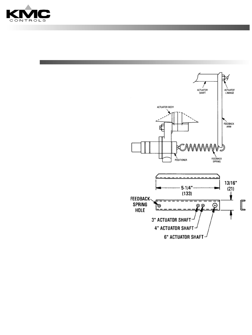
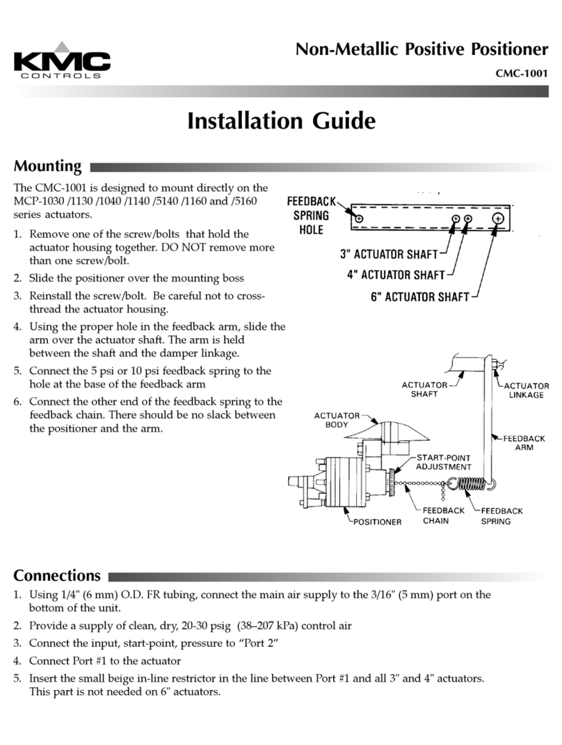
4. Using the proper hole in the feedback arm (VTD-
1500), slide the arm over the actuator shaft. The
arm is held between the shaft and the damper
linkage.
5. Connect the 5 psi or 10 psi feedback spring
(ordered separately—see chart) to the hole at the
base of the feedback arm.
Mounting 1
Connections 2
Maintenance 2
Adjustments and Calibration 2
More Information 2
Important Notices 2
All dimension are in inches (mm)
6. Connect the other end of the feedback spring
to the feedback chain. There should be no slack
between the positioner and the arm.
CMC-1001 2 Installation Guide
© 2014 KMC Controls, Inc. 107-019-01B
KMC Controls, Inc.
19476 Industrial Drive
New Paris, IN 46553
574.831.5250
www.kmccontrols.com
[email protected]
Important Notices
The material in this document is for information pur-
poses only. The contents and the product it describes
are subject to change without notice. KMC Controls,
Inc. makes no representations or warranties with respect
to this document. In no event shall KMC Controls, Inc.
be liable for any damages, direct or incidental, arising
out of or related to the use of this document.
Maintenance
No routine maintenance is required. Each compo-
nent is designed for dependable, long-term reliabil-
ity, and performance. Careful installation will also
ensure long-term reliability and performance.
Adjustments and Calibration
Once connections are complete and supply air is
applied, turn the start-point adjustment dial until the
actuator begins to move.
For example, a start point of 4 psi with a 5 psi span
spring will yield an operating range of 4–9 psi.
Connections
1. Using 1/4" (6 mm) O.D. FR tubing, connect the
main air supply to the center 3/16" (5 mm) port.
Provide a supply of clean, dry, 20–30 psi (38–207
kPa) control air.
2. Connect the control signal to Port 2 (input).
3. Connect Port 1 (output) to the actuator. For 3" and
4" actuators (only), insert the small beige in-line
restrictor (VTD-2500) in the line between Port 1
and the actuator. The restrictor is not needed for
6" actuators.
More Information
For accessories, speci-
cations, and other
information, see the
CMC-1001 Data Sheet
on the KMC web site
(www.kmccontrols.
com).
CAUTION
Pneumatic devices must be supplied with clean, dry
control air. Any other medium (e.g., oil or moisture
contamination) will cause the device to fail.

Other KMC Controls Valve Positioner manuals

KMC Controls CMC-1002 User manual

KMC Controls

KMC Controls CMC-1002 User manual

KMC Controls CMC-1001 User manual

KMC Controls

KMC Controls CMC-1001 User manual

Popular Valve Positioner manuals by other brands

Lang LHT500 Assembly instruction

Lang

Lang LHT500 Assembly instruction

Parker 406LXR Series product manual

Parker

Parker 406LXR Series product manual

Nupi 00IPOS01 operating instructions

Nupi

Nupi 00IPOS01 operating instructions

Omron H8PS-8AF manual

Omron

Omron H8PS-8AF manual

SMC Networks IP8101 Series Operation manual

SMC Networks

SMC Networks IP8101 Series Operation manual

Samson 3767 TRANSLATION OF ORIGINAL INSTRUCTIONS

Samson

Samson 3767 TRANSLATION OF ORIGINAL INSTRUCTIONS

GE FVP110 Maintenance manual

GE

GE FVP110 Maintenance manual

GE Baker Hughes Masoneilan SVI FF Installation and operation manual

GE

GE Baker Hughes Masoneilan SVI FF Installation and operation manual

Crane WESTLOCK CONTROLS DIGITAL EPIC-2 Technical manual

Crane

Crane WESTLOCK CONTROLS DIGITAL EPIC-2 Technical manual

Flowserve P3 Series Installation operation & maintenance

Flowserve

Flowserve P3 Series Installation operation & maintenance

Westlock 793 Installation, setting, operation

Westlock

Westlock 793 Installation, setting, operation

Power-Genex ASD-5000 Series Instructions and operating manual

Power-Genex

Power-Genex ASD-5000 Series Instructions and operating manual

VAC D400 Commissioning instructions

VAC

VAC D400 Commissioning instructions

Festo CMSX-P-S-A1-C-U-F1-D series operating instructions

Festo

Festo CMSX-P-S-A1-C-U-F1-D series operating instructions

Robertshaw P2 quick start guide

Robertshaw

Robertshaw P2 quick start guide

Vector TCY-MZ Operation manual

Vector

Vector TCY-MZ Operation manual

Val Controls I 24-B Series Hardware manual

Val Controls

Val Controls I 24-B Series Hardware manual

Plast-O-Matic V200 instructions

Plast-O-Matic

Plast-O-Matic V200 instructions

manuals.online logo
manuals.online logoBrands
  • About & Mission
  • Contact us
  • Privacy Policy
  • Terms and Conditions

Copyright 2025 Manuals.Online. All Rights Reserved.