MEWOI MEWOI-JY218 User manual

Sound Level Meter
MEWOI-JY218(Class 1)
User Manual
www.mewoi.com


CONTENT
I. Brief Introduction....................................................................... 1
II. First time use............................................................................. 1
III. Technical Specification.............................................................. 1
IV. Structure.................................................................................... 3
V. Display interface........................................................................ 4
VI. Keypad interface ....................................................................... 5
VII. Instrument operation................................................................. 5
VIII. Calibrating the meter................................................................. 8
IX. Reference Information for Periodic Testing............................... 8
X. Serial connection......................................................................11

-1-
I. Brief Introduction
Welcome to your new sound level meter. You’ve taken a great
step towards protecting people’s hearing and this entry level meter
will make it quick and easy for you to take simple noise
measurements, providing you with the basic data you need.
It is designed to IEC 61672 to Class 1. The instrument has ‘F’
(fast), ‘S’ (slow) and ‘I’ (Impulse) time response and ‘A’, ‘C’ and ‘Z’
frequency weightings. Additional features include max, min and
LCpeak hold for the duration of the measurement.
II. First time use
Before using your meter for the first time, please check the
contents of your instrument’s case, which should include the
following:
1, Sound level meter and Class 1 microphone
2, Windshield
3, 2 x AA batteries(Not included forAir Shipment)
Before starting a measurement, remove the black microphone
protective cap (if fitted) and where necessary, place the
windshield carefully over the end of the microphone capsule.
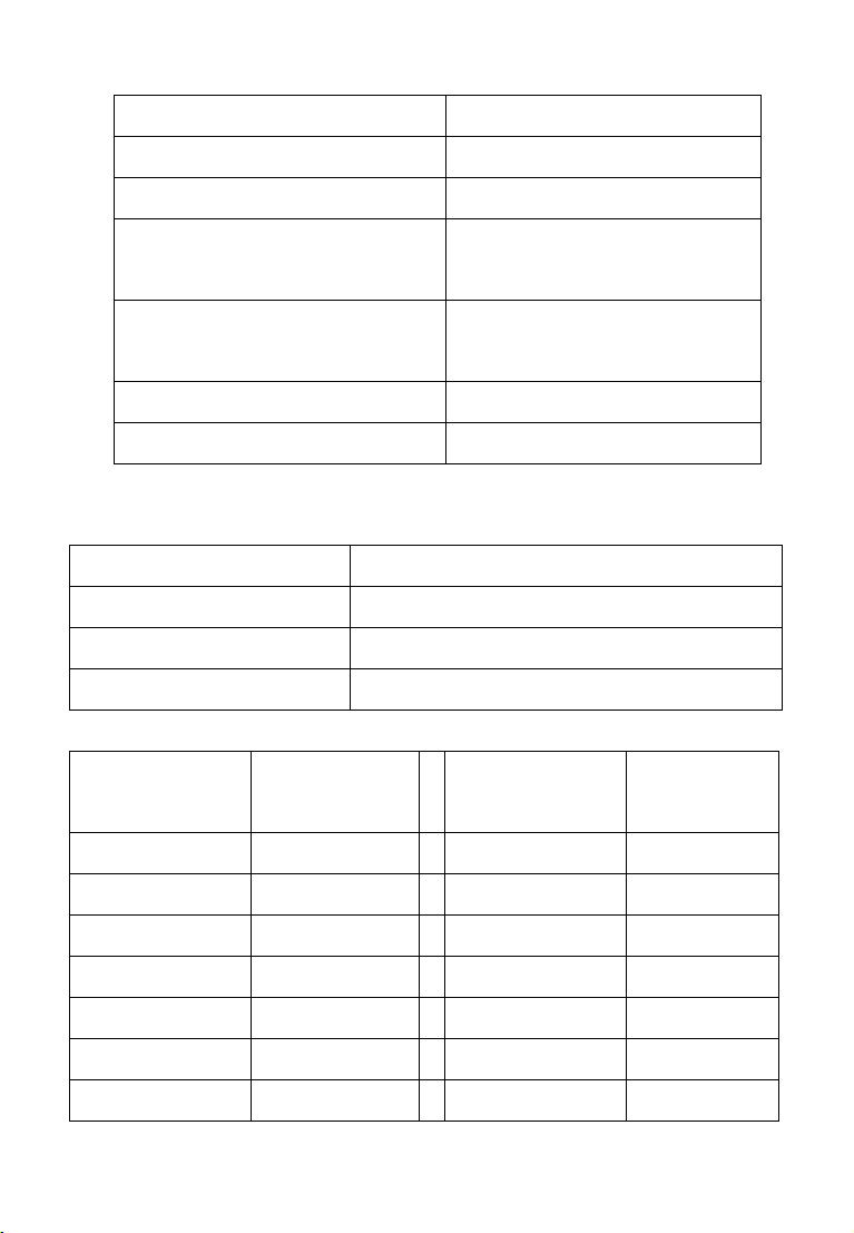
III. Technical Specification
Standards
IEC 61672-1:2013 Class 1
Measurement
range
30dB (A)~130dB (A)
40dB (C)~130dB (C)
45dB (Z)~130dB (Z)
Frequency
weighting
A, C and Z
Time weighting
Fast (F), Slow (S) and Impulse (I)
Display
functions
Normal, Maximum, Minimum, C peak
Measurement
functions
LAF, LAS, LAI, LCF, LCS, LCI, LZF, LZS, LZI,
LCpeak

-2-
Noise floor
< 25dB (A) and 35dB (C)
Display flags
Alarm Limit, Overload, Under-range
Auto calibration
range
±4.5dB
Reference point
94dB (1kHz), 92.9dB (8kHz)
Settling time
60s
Display
Backlit 128×64 LCD
Resolution
0.1dB
Electrical inputs
5V power in via mini USB
Power
2 x AA/LR6 1.5V batteries
or 5V DC via Mini USB input
Battery life
24 hours with alkaline batteries
Microphone
½" pre-polarized electret condenser, 50mV/Pa
Operating
temperature
-10°C to +50°C
Operating
humidity
25%~90%
Atmospheric
pressure
65kPa~108kPa
Storage
Temperature
-20°C to +60°C
Dimensions
215mm×68mm×32 mm
Weight
220g (including battery)
Electrical
Outputs
AC (tip 3.5mm jack) and DC (middle 3.5mm jack)
DC Output
voltage 15mV/dB, range 450mV~1950mV
AC Output
RMS 2V
-3-
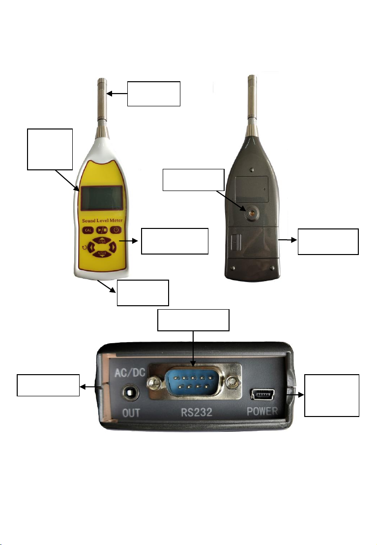
IV. Structure
1. Microphone 2. Backlight Display 3. Control Keypad
4. Connectors 5, Connectors 6, Tripod mount
7, Battery Cover 8, RS232 9, AC/DC Output 10, USB
Microphone
Backlight
Display
Control Keypad
Connectors
Tripod mount
Battery Cover
RS232 for Printer
USB Power
Input
AC/DC Output
-4-
V. Display interface
1, Main Display
2, Calibration display (press the CAL button)
3, Measurement display
Under-range
indicator
Measurement
Indicator
Overload
indicator
Measurement
Type
Battery Level
Measurement Data
Calibrator level
Correction to
Be applied
Measurement Data
Overall
Measurement Value
Under-range/
Overload
Indicator
Measurement
Duration

-5-
VI. Keypad interface
VII. Instrument operation
Fit new batteries by sliding the battery cover open and inserting
twoAA batteries in the correct orientation.
Switch on and allow the instrument to settle for 60 seconds before
calibrating.
Before starting a measurement, calibrate the instrument as per the
guidance in Chapter 8 of this manual.
7.1 Selecting the frequency and time weighting
Select the measurement frequency and time weighting required:
To toggle between A, C and Z weighting, press .
To toggle between fast, slow and impulse weighting,press .
Measurement start/stop
Perform calibration
Soft key: CAL/Print
Time weighting toggle
Reset max, min,
LCpeak
Frequency weighting toggle
Measurement start/stop
Select/View

-6-
The measurement type is displayed in the main window:
LAF -A frequency weighting and fast time weighting
LCF - C frequency weighting and fast time weighting
LZF - Z frequency weighting and fast time weighting
LAS -A frequency weighting and slow time weighting
LCS - C frequency weighting and slow time weighting
LZS - Z frequency weighting and slow time weighting
LAI -A frequency weighting and impulse time weighting
LCI - C frequency weighting and impulse time weighting
LZI - Z frequency weighting and impulse time weighting
To toggle the measurement values, press . This will toggle
through the following measurement values if the meter is set to
LAF:
LAF > LAFMax > LAFMin > LCpeak > LAF
Integrating averaging measurements Lxeq1s and Lxeq8h are
available for measurements on the instrument.
7.2 Maximum, minimum and LCpeak values
Maximum, minimum and LCpeak values are shown for the duration
of time since the meter was switched on, or since the reset button
was last pressed.
These values can be reset by pressing (Reset).
7.3 Performing and printing a measurement
Press to start or stop a measurement. Whilst a measurement
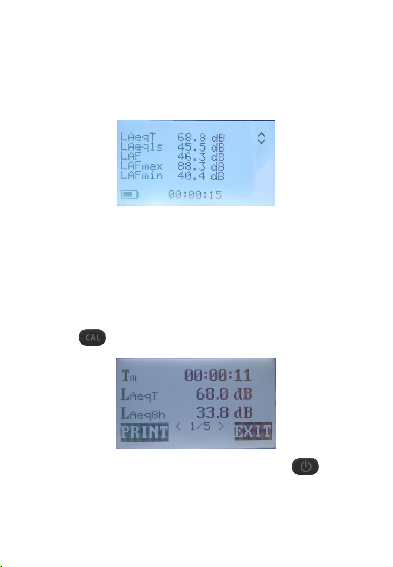
-7-
is running, the latest values will be displayed on the screen, with
the measurement duration shown at the bottom. Alternative
measurement parameters can be viewed by pressing the left/right
arrow buttons.
Overload and under-range are denoted by the ^ and v indicators in
the top right corner of the screen.
After stopping a measurement, the overall measurement values
are displayed. Press the left/right arrows to scroll through the
overall measurement values.
If a printer is attached, the results can be printed by
pressing (Print).
The measurement view can be cancelled by pressing (Exit).
-8-
VIII. Calibrating the meter
Before making a measurement, it is important that you calibrate
your instrument with an acoustic calibrator.
To start the process of calibration, ensure the microphone is fitted
correctly and place the acoustic calibrator over the microphone.
Press to enter the calibration menu.
Use the arrow keys to set the CAL LEVEL to the acoustic
calibration level (Normally 1kHz 94.0dB for the calibrator).
Use the arrow keys to set the CORRECT value to 0.2dB, which will
make the adjustment for the gap between the calibrator and the
microphone (pressure field of the acoustic calibrator and the free
field of the instrument and microphone).
This will result in the meter reading 93.8dB when a 94dB calibrator
is used.
Switch on the acoustic calibrator and press to automatically
calibrate the meter.
Press to exit from the calibration display and to return back to
the main display.
IX. Reference Information for Periodic Testing
Reference level (1kHz)
94dB
Reference level (8kHz)
92.9dB (A)
Linear range 8kHz
30-130dB
-9-
Linear range 4kHz
30-130dB
Linear range 1kHz
30-130dB
LCPeak maximum (500Hz, 1kHz, 8kHz)
133dB
Self-generated noise floor
A weight = 25dB
C weight = 35dB
Self-generated noise floor with mic fitted
A weight = 25dB
C weight = 35dB
Dummy microphone capacitance
18pF
Recommended dummy microphone
HY7314
Multi-frequency acoustic calibrator correction data (set to pressure
and test on A weighting)
Frequency
Correction
125Hz
0.0
1kHz
0.2
8kHz
2.6
Free field correction for HY205 microphone.
Frequency/kHz
Free field
Correction/dB
Frequency/kHz
Free field
Correction/dB
1
0.1
6.3
1.7
1.25
0.1
8
2.6
1.6
0.2
10
4.4
2
0.3
12.5
5.3
2.5
0.5
16
6.5
3.15
0.7
18
7.1
4
1.0
20
7.8

-10-
5
1.4
---
---
Case reflection and windshield attenuation data.
Frequency/kHz
Case Correction
Windshield
Correction
Uncertainty
63
0
0
0.27
125
0
0
0.27
250
0.13
0.05
0.27
500
0.18
0.08
0.27
1000
0.09
0.1
0.27
2000
-0.16
0.26
0.27
4000
0.01
0.53
0.32
8000
-0.10
0.26
0.30
16000
-0.17
-0.58
0.29
Add the above data to your measurement to correct.
Directionality plots and case reflection plots

-11-
X. Serial connection
DB9, RS232 communication rate at 9600 Baud.
1 bit start, 8 bits data, 1 bit stop, no parity.
Command
Code
(ASCII)
Description
Instant level
L
Send instant level after receiving command 'L'.
Maximum level
M
Send maximum level after receiving command 'M'.
Minimum level
N
Send minimum level after receiving command 'N'.
LCpeak
P
Send LCpeak after receiving command 'P'.
Reset
R
Reset the maximum, minimum and LCpeak value
after receiving command 'R', and then send 'R' as
the response.
Toggle frequency
F
Toggle the frequency weighting between A, C and

-12-
weighting
Z after receiving the command 'F', and then send
'F' as the response.
Toggle time weighting
T
Toggle the time weighting between F and S after
receiving the command 'T', and then send 'T' as
the response.
Please note that commands 'R', 'F', and 'T' will not work out if the
measurement is on-going, because the parameters cannot be
changed during the measurement. They will just send the
responses to tell the user that the instrument has received the
commands.
The data format of instant level, maximum, minimum and LCpeak
got from the instrument:
start byte (0x01) + data (5 bytes) + checksum (2 bytes) + end byte
(0xFF)
for example: (prefixes '0x' are omitted)
01 30 39 34 2E 32 00 FD FF
"30 39 34 2E 32" is the hex data of the ASCII string "094.2".
"00 FD" is the checksum calculated just like this:
30+39+34+2E+32=00FD.

Your Testing Specialist
Table of contents
Other MEWOI Measuring Instrument manuals

MEWOI
MEWOI MEWOI9000G User manual

MEWOI
MEWOI MEWOI7900 User manual

MEWOI
MEWOI MEWOI7300E User manual

MEWOI
MEWOI MEWOI1330B User manual

MEWOI
MEWOI MEWO1000T User manual

MEWOI
MEWOI MEWOI8100E User manual

MEWOI
MEWOI MEWOI-HY128 Series User manual

MEWOI
MEWOI MEWOI9000 User manual

MEWOI
MEWOI MEWOI1000 User manual

MEWOI
MEWOI 7800 User manual


Popular Measuring Instrument manuals by other brands

Milwaukee
Milwaukee 2236-20 Operator's manual

T&R
T&R KV3-250 mk2 Operating and maintenance manual

RINGSPANN
RINGSPANN Brake HS 165 FHM Installation and operating instructions

Agilent Technologies
Agilent Technologies E5900B user guide

Industrial Scientific
Industrial Scientific ATX612 instruction manual

Aktakom
Aktakom ACM-2031 user manual


