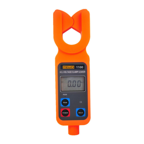
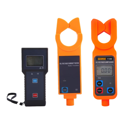
MEWOI MEWOI1330B User manual

Wireless High Voltage Hook Type Current Meter
MEWOI1330B
User Manual
www.mewoi.com

CONTENT
Precaution For Use................................................................................................1
1.Introduction.........................................................................................................2
2.Electrical Symbols..............................................................................................2
3.Technical Specification .......................................................................................3
4.Structure.............................................................................................................4
5.LCD Display .......................................................................................................5
5.1.LCD Display Screen..................................................................................5
5.2. Explanation for Special Symbols.................................................................5
5.3.Display Demonstration ..............................................................................5
6.Operation Method...............................................................................................6
6.1. Detector Operation......................................................................................6
6.1.1. Start Up / Shut Down..............................................................................6
6.1.2. Normal Test............................................................................................6
6.1.3. Test Area................................................................................................7
6.1.4. Data Transmission .................................................................................8
6.2. Receiver Operation.....................................................................................8
6.2.1. Start Up / Shut Down..............................................................................8
6.2.2. Data Reception ......................................................................................8
6.2.3. Data Hold...............................................................................................8
6.2.4. Data Storage..........................................................................................8
6.2.5. Data Access...........................................................................................8
6.2.6. Data Delete............................................................................................9
7.Replace Batteries...............................................................................................9
8.Accessories........................................................................................................9

1
Precaution For Use
Thanks you for purchasing our MEWOI1330B Large Caliber Wireless H/L Voltage Hook
Type Current Meter. In order to better for use of the product, please be certain:
——Read this user manual in detail, the operator must fully understand the manual
and then can be able to operate to the field test.
——Comply with the operating cautions in this manual.
Under any circumstance, shall pay special attention on safety in using this meter. Especially
when measuring voltage circuit over AC100V and above
If the tested line voltage over 600V, it must be used insulation rod to connection.
Because the high voltage circuit is very dangerous, the operator must be strictly trained and
obtain the national high voltage operation certification before using the meter for field test.
It is strictly forbidden to use this meter to test bare wires or busbars of the voltage exceed
500kV.
Pay attention to the text labeled on the panel and backplane of the Meter.
Do not place and store the meter in high temperature and humidity or dewy places and
under direct sunlight for a long time.
Replace the battery, please pay attention to the battery polarity. If you not use the leaker for
a long time, please take out batteries.
Disassembly, calibration, and repair of this tester must be performed by authorized
personnel.
If meter`s components are damaged, Please stop to use.
Due to the reason of this instrument, if it is dangerous to continue using, should stopped and
sealed immediately ,and handled by an authorized institution.
The meter manual with the danger mark " ", users must follow instructions to operate
safely.
The meter manual with the extremely dangerous mark " ", users must in strict follow
instructions to operate safely.
It is recommended that the meter should make insulation strength test at least once a year
(AC 110kV/rms telescopic insulation rod is fully opened between the two ends).

2
1. Introduction
MEWOI1330B Large Caliber Wireless H/L Voltage Hook Type Current Meter break
through the traditional structure, specially designed and manufactured for measuring high
voltage current, the unique hook type opening mouth structure realizes the unimpeded
measurement, and veryconvenient for field test. Themeter is composed of special large-caliber
hook type current meter with high voltage insulation rod, equipped with wireless receiver, which
can receive the measured data within 100 meters straight line distance, current range: AC
0.00A-9999A. In low voltage lines below 600V, the line current can be measured directly by
hook meter without insulation rod.
MEWOI1330B Large Caliber Wireless H/L Voltage Hook Type Current Meter connect
with the insulation rod, can be used for current measurement of the lines with insulation skin
below 500kV or bare wires high voltage lines below 35kV. Online measurement and with data
hold, data storage and wireless transmission and other functions, Its special hook type current
meter can be easily approached to the measured wire by insulation rod, which can be directly
hung on the line for measurement, saving time and more effective. Widely used in substation,
power plant, industrial and mining enterprises, detection stations, electrical maintenance
departments for current detection and field electrical work etc.
It can also replace the H/L voltage turns ratio tester, which can measure the H/L voltage
current of the primary circuit and secondary circuit respectively, and then calculate to get the
H/L voltage turns ratio. Insulation rod is portable, with moisture-proof, high temperature
resistance, impact resistance, bending resistance, high insulation, telescopic and other
characteristics.
2. Electrical Symbols
Extremely dangerous! The operator must strictly follow the safety rules, otherwise
there would be danger of electric shock, causing personal injury or injury accident.
Dangerous!The operator must strictly follow the safety rules, otherwise there would
be danger of electric shock, causing personal injury or injury accident.
Warning!Operators must strictly follow safety rules , otherwise personal injury or
equipment damage may occur
Alternating Current (AC)
Direct Current (DC)

3
3. Technical Specification
Function
Measurement of high voltage AC current, low voltage AC current,
on-line monitoringAC current
Power Supply
DC6V Alkaline Dry Battery (1.5V AAA X4pcs)
Test Mode
Clamp CT
Transmission Mode
433MHz wireless transmission, distance about 100m
Display Mode
4 digital LCD display, backlight function, suitable for dark place.
LCD Dimension
47mm×28.5mm
Meter Dimension
Detector: 210mm×246mm×45mm; Receiver:
78mm×165mm×42mm
CT Size
Φ128mm
Sampling Rate
2 times/second
Measure Range
0.00A ~9999A(50/60Hz Auto Identification)
Resolution
0.01A
Shift
0.00A ~9999A Automatic Shift
Test Accuracy
±2%±5dgt(The wire is located near the center of the bottom of the
u-type clamp, 23℃±2℃)
Position Error
The measured conductor should be located as close as possible to
the center of the top of the hook type clamp, and not close to the
top of the u-type clamp. The test error on the top of the u-shaped
clamp will increase by about one time or more
Data Storage
99 sets, in storage process “MEM” symbol display, “FULL” symbol
flash indicate storage is full
Line Voltage
Test with insulation skin wires below 60KV, test with bare wires
below 500KV (operated with insulation rod, The telescopic
insulation rod is fully opened)
Data Hold
In general test mode, press HOLD key to hold data, “HOLD” symbol
display. press HOLD Key once again to cancel this function
Data Access
“MR” symbol display, it can look over all the stored data
Overflow Display
Exceed measurement range overflow function: “OL A” symbol
display
No signal Indication
When the receiver has not received transmit signal, dynamic display
“no- -”symbol
Auto Shut Down
About 15 minutes after boo up, the meter will shut down
automatically without any operation, to decrease the battery
consumption.
Battery Voltage
When the battery voltage is lower than 4.8V, the receiver display low
battery voltage symbol” ”(the detector low voltage display “ ”
symbol, the receiver low voltage continue display), remind to replace

4
battery
Meter Weight
Detector: About 300g,
Receiver: 280g
Total weight of meter: about 2300g (including insulation rod and
battery.)
Working Temperature
-10°C ~40°C ; Below 80%Rh
Storage Temperature
-10°C ~60°C ; Below 70%Rh
Interference
Should avoid 315Mhz,433Mhz Same frequency signal interference
Insulation Rod
Dimension
Φ45mm,Contraction state:850mm,Extension state:3600mm
Insulation Strength
AC 220KV/rms (The telescopic insulation rod is fully opened)
Structure
Anti-Dripping Type II
4. Structure
4.1. Hook type Clamp 4.2. Detector
4.3. Power indicator 4.4. Detector POWER key
4.5. Connection end with insulation rod 4.6. Receiver POWER Key
4.7. Receiver HOLD Key 4.8. Receiver LCD
4.9. Receiver 4.10. Receiver antenna
4.11. Insulation Rod 4.12. Insulation rod adjustable interface

5
5. LCD Display
5.1.LCD Display Screen
5.1.1. AC Symbol
5.1.2. Low battery voltage symbol
5.1.3. Date storage symbol
5.1.4. Date access symbol
5.1.5.2-digit Storage Data Serial Number
5.1.6. Unit Symbol
5.1.7. Date Locked Symbol
5.1.8. Decimal System Radix Point
5.1.9.4-Digit LCD Digital Display
5.2. Explanation for Special Symbols
5.2.1. Low battery voltage symbol, when the battery voltage lower than 4.8V, this
symbol display, please replace battery in time.
5.2.2. “OL A” symbol indicates that the measured current over limit range of the meter.
5.2.3. “MEM” storage mode, will display during the data storage.
5.2.4. “Full” symbol, when the storage data is full of 99 groups of data, will flash display
“FULL” symbol, and cannot continue to store data.
5.2.5. “MR” data access symbol, display during data access, meanwhile, it will display the
serial number of storage data.
5.2.6. “End” exit symbol, display during the exit.
5.2.7. “dEL” data delete symbol, display during delete data.
5.2.8. “no- -” No received signal indication, dynamic display, it may the meter not in test
mode, or adjust received signal location and distance
5.3.Display Demonstration
5.3.1. ——The tested current: 2.00A
5.3.2. ——Locked display Data
——The data is automatic
stored as group 3
——The tested current: 160A
5.3.3.——The tested current: 571A
——Low battery voltage symbol
please replace battery.

6
5.3.4.——Look up data of group 3 in storage
——The tested current: 160A
5.3.5.—— “FULL” flash display:
Storage full of 99 groups
——must clear storage and then
Storage again
5.3.6.——data delete indication “dEL”
5.3.7.——Exit function indication “End”
5.3.8.——“no- -”Dynamic display: not
received signal
6. Operation Method
Before usage, carefully check whether all parts of the meter are damaged. Only
when there is no damage can be used
According to manual instructions to install the battery
6.1. Detector Operation
6.1.1. Start Up / Shut Down
Press POWER button to power on, indicator light up, enter into normal test mode. 15
minutes after power on, the meter will shut down automatic without any operation.
6.1.2. Normal Test
Extremely dangerous! The operator must strictly follow the safety rules, otherwise
there would be danger of electric shock, causing personal injury or injury accident.
Dangerous! It is strictly forbidden to use this meter to test bare wires or busbar with
voltage over 110kV, otherwise there would be danger of electric shock, causing
personal injury or injury accident.
For high voltage test, the insulation rod must be connected and fully stretched.
Hold the end of the sheath of the insulation rod and use.
Must connect the meter with the special insulation rod
After normal boot up, connect with the insulation rod and move the detector hooked the

7
wire. Placing the wire in a central position at the top of the hook clamp or hung on the line
directly, which can ensure the accuracy of the measurement. After the test, the instrument can
be removed from the tested wire.
Attention! For safety, after test finish, please remove the meter away from the tested
wire
6.1.3. Test Area
If the receiver display “OL” symbol, indicate the tested current exceed the meter measure
upper limit. The tested wire should be located as far as possible at the center of the top of the
hook clamp (semicircle area at point A), or it can hung on the line directly for measurement. The
position error increase 2% at point B area, try to keep the tested wire away from C area,
otherwise the test error will larger.

8
6.1.4. Data Transmission
The meter has the function of wireless transmission test data. When the meter is in test
mode, the test results are transmitted to the receiver by wireless way, and the receiver displays
the test data real time and view clear.
Only in test mode will transmit the signal. If the receiver does not receive the transmitted
signal will dynamically displayed "no--" symbol. Wireless transmit test data in straight line
distance about 100 meters.
6.2. Receiver Operation
6.2.1. Start Up / Shut Down
Press POWER key to start up, LCD display and enter into receive data mode. If the LCD
display is dark after start up, the battery voltage may be low, please replace the battery. After 15
minutes of the receiver start up, the LCD continues to blink, indicate that will automatic
shutdown. The LCD will automatic shut down after continuous flashing 30 seconds to reduce
battery consumption. If in LCD continuous flashing and press POWER key, the meter will
continue to work.
Under HOLD mode, press POWER key to shut down.
Under data access mode, long press POWER key (exceed 3 seconds) to exit data access
mode, return to data receive mode, press POWER key again to shut down. Exit data access
process will display “End” symbol.
6.2.2. Data Reception
The receiver is in receiving mode after normal start up. If there is transmitted data, the
receiver will display the test results in real time. If not receive signal, the receiver will
continuously search for the signal and dynamically display the "no--" symbol.
6.2.3. Data Hold
In the mode of receiving data, press HOLD key can hold LCD display, and “HOLD” symbol
indication. Press HOLD key again to cancel data lock state, return to receiving data mode,
“HOLD” symbol disappear.
6.2.4. Data Storage
In the mode of receiving data, press the HOLD key to hold the data while the receiver
automatically numbers and stores the present hold data, and the "MEM" symbol flashes once in
the stored process. The receiver can store 99 groups’ data, if the storage is full, “FULL”symbol
will continue flashing display, memory must be cleared and then could store again.
6.2.5. Data Access
In the mode of receiving data, press HOLD+POWER key enter into data access mode,
“MR” symbol display while will automatically display storage data of the group 1. Then press

9
HOLD key or POWER key to read the stored data by turning upward or downward in cycle.
Automatically returns the first group of data when browse to the last group of data stored.
Long press POWER key (over 3 seconds) to exit from data access mode, return to
receiving data mode. During the exiting display “End” symbol.
6.2.6. Data Delete
In data access mode, press HOLD + POWER key to delete all storage data, and return to
data receive mode. During the deleting data display “dEL” symbol.
7. Replace Batteries
Warning! Do not test if the battery cover plate is not well covered, otherwise it is
dangerous.
Pay attention to the battery polarity, or will damage the meter
Do not mix new and old batteries for use
7.1. When battery voltage of the receiver is lower than 4.8V, the meter will continue to
display “ ” symbol, indicate that low battery. Please replace batteries in time.
7.2. Power off and make sure the meter is off state. Loosen two screws and open the
battery cover plate to replace new qualified batteries, pay special attention on the battery
specification and polarity, and then cover the board well and fasten the two screws.
7.3. Press POWER key to check whether the meter can start up normally or not. If not,
please repeat the operation according the step 2.
8. Accessories
Detector
1PCS
Receiver
1PCS
Wireless Antenna
1PCS
Stretch Insulation Rod
1PCS
Meter Case
1PCS
Manual/ Maintenance Card/ Certificate
1SET

10
Your Testing Specialist
Table of contents
Other MEWOI Measuring Instrument manuals
MEWOI
MEWOI MEWOI1000 User manual
MEWOI
MEWOI MEWOI8000B User manual
MEWOI
MEWOI MEWOI7300E User manual
MEWOI
MEWOI MEWOI-HY128 Series User manual
MEWOI
MEWOI MEWOI-JY218 User manual

MEWOI
MEWOI MEWOI400 User manual
MEWOI
MEWOI MEWOI7900 User manual
MEWOI
MEWOI MEWOI9000 User manual
MEWOI
MEWOI 8000 User manual
MEWOI
MEWOI MEWOI1310B User manual
Popular Measuring Instrument manuals by other brands
Extech Instruments
Extech Instruments 407860 user guide
HACH LANGE
HACH LANGE Pocket Colorimeter II user manual

PCB Piezotronics
PCB Piezotronics 350B43/NC Installation and operating manual

Alpsat
Alpsat Satfinder 2 HD Slim user guide

Seaward
Seaward apollo 400 operating instructions

radiance
radiance RT818/E product manual
