MEWOI MEWOI4000 User manual

Digital Earth Resistance Tester


CONTENT
Warning................................................................................................... 1
I.Introduction........................................................................................ 3
II.Measuring Range and Accuracy................................................... 4
III.Technical Specifications................................................................ 4
IV.Tester Structure.............................................................................. 6
V.Measuring Principle........................................................................ 7
VI. Function Quick Check..................................................................... 8
VII. Operation Methods......................................................................... 8
1.Switch On/Off............................................................................ 8
2.Battery Voltage Check................................................................ 8
3.Insert and Connection of Rods................................................... 8
4.Grounding Voltage Measurement............................................... 9
5.Wire Resistance Verification.................................................... 10
6.Precision Measurement............................................................ 10
7.Simple Measurement.................................................................11
8.Backlight Control..................................................................... 13
9.Alarm Settings.......................................................................... 13
10.Data Lock/Storage.................................................................. 13
11.Data Reading/Deletion........................................................... 13
12.Data Upload ........................................................................... 14
VIII. Battery Replacement.................................................................. 14
IX.Accessories.................................................................................. 15
-1-
Warning
Thanks for your purchase of MEWOI4000 Digital Earth
Resistance Tester of our company. For better use of the
product, please make sure:
---read this user manual in details.
---abide by the safety regulations and precautions strictly.
The tester is conforming to IEC61010 on design, production
and test.
Under any circumstance, it shall pay special attention on
safety in use of this tester.
Please don’t use high-frequency signal generators like mobile
phone and etc. to avoid error during measuring.
Pay attention to words and symbols stick on the Tester.
It shall make sure that tester and accessories are in good
condition before use; it can be used only when there is no
damaged, naked or broken part in testing wires or insulation
layer.
During measurement, it is forbidden to touch bare conductors
and circuit under measurement.
Before measurement, please confirm whether FUNCTION
rotary switch has been set within the proper measuring range.
Confirm that connector plug of lead has been inserted in the
tester interface closely.
Please don’t impose over 600V A.C. or D.C. voltage on the
part between testing end and interface. Otherwise, it may have
damage on the tester.
Please don’t measure in an inflammable place. The flame
-2-
sparkle maybe cause explosion.
During usage of tester, please stop using it when exposed
metal is caused by broken enclosure or testing wires.
Please don’t keep or store the tester in the spot with
high-temperature and moisture, or condensation, and under
direct daylight radiation for a long time.
For replacing battery, please confirm testing wire has moved
apart the meter, and FUNCTION rotary switch is in “OFF”
position.
Please put the used batteries in appointed collection place.
The Tester has no auto shut-off function. Please set
FUNCTION rotary switch to “OFF” after usage.
When the meter displays battery low voltage symbol ,and
you need to replace the battery in time.
If the Tester is not going to be used for a long period, remove
the battery.
Pay attention to measuring range and usage environment
stipulated for the Tester.
This measuring device is only to be used, disassembled,
adjusted and repaired by qualified personnel with authorization.
When it may cause hazard by continuous use for the reason
of the Tester itself, it shall immediately stop using it and deposit it
at once, leaving it for disposal by authorized agency.
For risk of danger icon in manual , users must perform
safety operations strictly in compliance with the manual content.

-3-
- 2-
I.Introduction
MEWOI4000 Digital Earth Resistance Tester is specially
designed and manufactured for field measurement, adopting the
latest digital and micro-processing technology, 3-pole or 2-pole
method for earth resistance measurement, with a unique function
of wire resistance verification, anti-interference capability and the
ability to adapt to the environment, to ensure high precision, high
stability and reliability for prolonged measure, which is widely used
in electric power, telecommunications, meteorology, oil field,
construction, lightning protection, industrial electrical equipment
and other earth ground resistance measurement.
MEWOI4000 Digital Earth Resistance Tester has a unique
function of wire resistance verification ,more accurate on
measuring on-site low value earth ground resistance, which can
avoid error caused by resistance change due to prolonged usage
of testing wire; avoid error caused by testing wire that is failed to be
fully inserted into tester interface or by poor contact; avoid error
caused by users’ replacing or lengthening testing wires.
MEWOI4000 Digital Earth Resistance Tester is composed of
host machine, monitoring software, testing wires, communication
wires and others. The large LCD display of host machine is with
blue backlight and bar graph indicating that can be seen clearly. At
the same time it can store 400 sets of data, fulfilling historical
inquiry and online real-time monitoring through monitoring
software, dynamic display, with the maximum, minimum, and
mean indicators, with alarm settings and alarm indicator, and with
the functions like historical data access, reading, preservation,
report forms, printing and so on.
-4-
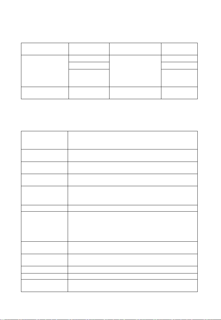
II.Measuring Range and Accuracy
Measuring
Functions
Measuring
Range
Accuracy
Resolution
Earth Ground
Resistance
0.01Ω~20Ω
±1%rdg±3dgt
(Auxiliary earth
ground resistance
100Ω±5%,voltage
to ground<10V)
0.01Ω
0.1Ω~200Ω
0.1Ω
1Ω~2000Ω
1Ω
Earth Ground
Voltage
0~600V AC
±1%rdg±3dgt
1V
(Remark: 23℃±5 ℃,below 75%rh)
III.Technical Specifications
Function
Earth ground resistance measurement, voltage to
ground measurement, low value resistance
measurement
Power Supply
DC 9V(Zi-Mn dry battery R14S 1.5V 6 PCS,
continuous standby for 300 hours )
Backlight
Controllable blue backlight, suitable for use in dark
place.
Measuring
Mode
Precise 3-pole measurement, simple 2-pole
measurement
Measuring
Method
Earth ground resistance: rated current change-pole
method, measurement current 3mA Max,820Hz;
Voltage to ground: average value rectification
Data Mode
Average value, maximum, minimum
Wire Resistance
Verification
Avoid error caused by testing wire that is failed to be
fully inserted into tester interface or by poor contact or
by users’ replacing or lengthening testing wires,
making it more accurate for earth ground resistance
measurement.
Display Mode
4-digital super-large LCD display, blue screen
backlight
Measuring
indicator
During measurement, LED flash indicator, LCD count
down display
LCD Dimension
128mm×75mm;Display field:124mm×67mm
Dimension
L×W×H: 215mm×190mm×95mm
Testing Wires
Three wires: each for Red 20m, Yellow 10m, and
Green 5m

-5-
Simple Testing
Wire
2 wires: each for Red 1.6m and Green 1.6m
Auxiliary
grounding rod
2 PCS:Φ10mm×150mm
Measuring Rate
Voltage to ground: about 3 times/second; earth
ground resistance: about 5 seconds/time
Measuring
Times
Over 5000 times
(Measuring 10Ω for one time on 20Ω range and take a
pause for 25s)
Circuit Voltage
Measuring voltage to ground: measuring below AC
600V
RS232 Interface
Possess RS232 interface, software supervision,
storage data can be uploaded to computer, saved or
printed.
Communication
Wire
One piece of RS232 communication wire, with length
1.5m
Data Storage
400 sets, flash display “FULL”icon to indicate storage
is full
Data Hold
Data hold function: “HOLD”icon display
Data Read
Data read function: “READ” icon display
Overflow
Display
Exceeding measuring range overflow function: “OL”
icon display
Alarm Function
When measuring value exceeds alarm setting value,
there is “Toot-toot-toot” alarm hint
Battery Voltage
When battery voltage decreases to about 7.8V,
battery voltage low icon will display, reminding to
replace battery.
Power
Consumption
Backlight:25mA Max
Standby: 25mA Max(Backlight shut off)
Measurement:70mA Max(Backlight shut off)
Weight
Tester:1443g(including battery)
Testing Wires:847g(including simply testing wires)
Auxiliary grounding rod:468g(2 PCS)
Meter bag:915g
Working
Temperature &
Humidity
-10℃~40℃;below 80%rh
Storage
temperature &
humidity
-20℃~60℃;below 70%rh

-6-
Overload
Protection
Measuring earth ground resistance: between each
interfaces of E-P、E-C,AC 280V/3 seconds
Insulation
Resistance
Over 10MΩ(between circuit and enclosure it is 500V)
Withstanding
Voltage
AC 3700V/rms (Between circuit and enclosure)
Electromagnetic
Features
Wireless frequency electromagnetic field
Protection Type
IEC61010-1 、IEC1010-2-31 、IEC61557-1,5 、
IEC60529(IP54)、Pollution etc. 2、CAT Ⅲ300V
IV.Tester Structure
-7-
1. LCD 2. Button area 3. Rotary switch for selecting function
4. RS232 interface 5. Interface of testing wires
6. C(H)interface: Current electrode
7. P(S) interface: Voltage electrode
8. Einterface: Earth electrode 9. Testing wires
10. Auxiliary grounding rod 11. Simple grounding wires
12. Testing probe 13. Safety alligator clip
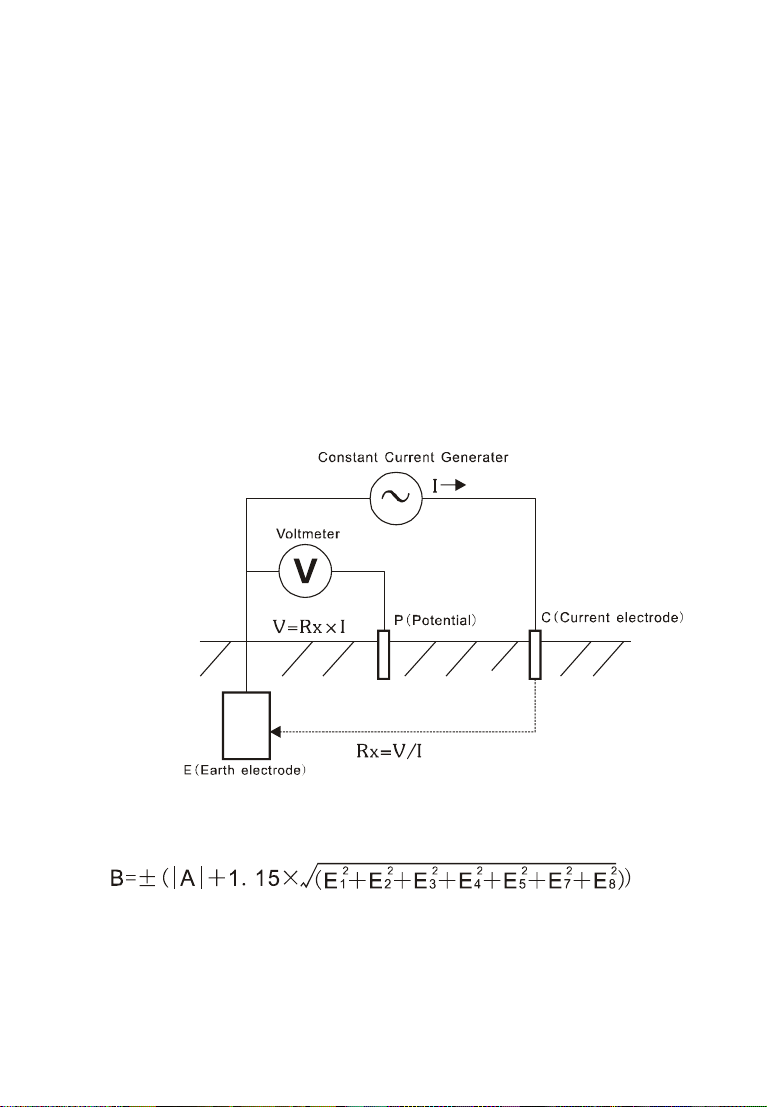
V.Measuring Principle
1. Voltage to ground measurement adopts average value rectification method.
2. Earth resistance measurement with fall-of-potential method. AC constant
current I (3mA Max, 820Hz) is applied between the measurement object E
(earth electrode) and C(current electrode), and finding out the potential
difference V between Eand P(potential electrode).
Rx=V/I
3.Maximum Operating Error:Operating error(B) is an error obtained within the
rated operating conditions, and calculated with the intrinsic error(A), which is
an error of the instrument used, and the error(E) due to variations.
A:Intrinsic error
E1:Variation due to position change
E2:Variation due to power supply voltage
E3:Variation due to temperature change
E4:Variation due to interference voltage change

-8-
E5:Variation due to contact electrode resistance
E7:Variation due to system frequency change
E8:Variation due to system voltage change
VI. Function Quick Check
FUCTION rotary
switch
Switch on/off ,Function shift, Switch gear
Up/down arrow
button
Data read/numerical value settings
Backlight button
Backlight control
START button
Start measuring
MODE button
Maximum, Minimum or Average value
mode, Move cursor
CLR button
Clear data/Delete data
MEM button
Data lock/storage/reading
AL button
Alarm function start/alarm critical value
settings
VII. Operation Methods
1.Switch On/Off
Rotate FUNCTION rotary switch to fulfill switch on and off. When rotary
switch button displays “OFF”for shut-off. The Tester has no auto shut-off
function, so please shut it off after usage in case of battery consumption
saving.
2.Battery Voltage Check
After switch on, if LCD displays low battery voltage icon “ ”,which
indicates that battery voltage is low, and please replace the battery in
compliance with instructions. Adequate battery power can ensure the
accuracy of measurement.
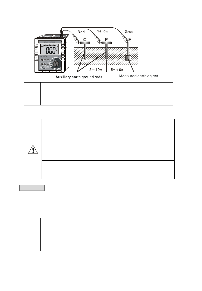
3.Insert and Connection of Rods
Shown as the following figure, stick the auxiliary earth rods Pand Cinto
the ground deeply. They should be aligned at an interval of 5-10m from the
earthed equipment under test. Connect the green wire to the earthed
equipment under test, the yellow wire to the auxiliary earth rod P and the red
wire to rod C from terminals E, P and C of the instrument in order.
-9-
Note
Please try to insert auxiliary grounding rod into moist soil. In case of dry
soil, sand, or gravel land, it requires adding water to keep auxiliary
grounding rod inserted place wet. In case of concrete place, it shall keep
auxiliary grounding rod flat and add water, and cover wet towels on earth
ground rod before measurement.
4.Grounding Voltage Measurement
Please make sure testing wire plug has been totally inserted into testers
corresponding interface and it may cause measurement value error for
incomplete insert or poor contact.
The tester cannot be used for commercial power supply voltage
measurement. For special situation that needs to measure, it can only
use P, E interface to connect for measurement. It is not allowed to
measure commercial power voltage in the case of short circuit of P, C
interface. Otherwise, measuring voltage in the grounding circuit of cutout
switch may cause cutout switch start.
On measuring grounding voltage, please do not impose over 600V
voltage on measurement connectors.
On measuring grounding voltage, please do not touch measured bare
conductors in case of electric shock.
After connecting of auxiliary grounding rod and testing wire, shift
FUNCTION rotary switch to “EARTH VOLTAGE”position. LCD display
voltage value to ground. Please note the measured voltage shall NOT exceed
600V.
In general, for measuring grounding voltage, it is only to connect the
testing wires corresponding to P, E interface.
Note
Before measuring earth ground resistance, firstly please
confirm voltage to ground must be lower than 10V.
Otherwise, the measurement value may cause excessive
error. At that time, firstly cut off power on measured
grounding equipment and make resistance measurement
after the grounding voltage is reduced.

-10-
5.Wire Resistance Verification
In order to improve precision and stability of field measurement of earth
ground resistance, avoid error due to wire resistance change due to prolonged
usage of testing wires; avoid error due to testing wire that is failed to be fully
inserted into tester interface or by poor contact; avoid error due to users’
replacing or lengthening testing wires and etc., wire resistance verification is
specially designed, as to "20Ω"grade, which is more accurate on low value
resistance measurement.
After connection of testing wire and the Tester, connect the other end of
all testing wires in short circuit, as the following figure, set FUNCTION rotary
switch to the corresponding earth ground resistance measurement position,
press button to start verification. During verification, LED indicator flashes,
LCD displays, and after verification, LED displays wire resistance value and
stores it. For this time switch on, it will automatically deduct the verified wire
resistance value from earth ground resistance measurement.
It will not preserve the verified wire resistance value on switching off. It
needs re-verification for next time switching on.
6.Precision Measurement
Please make sure testing wire plug has been totally inserted into testers
corresponding interface and it may cause measurement value error for
incomplete insert or poor contact.
As to low value earth ground resistance measurement, it will be more
accurate after wire resistance verification.
On measuring grounding voltage, between E and C interface, it will occur
the maximum voltage about 50V! Please do not impose voltage on
measurement interface. Please pay attention to avoiding electric shock
accident.
On measuring earth ground resistance, testing wires cannot be mixed
around, which shall be measured separately.
Try to choose the spot with more water to deeply bury auxiliary grounding
rods P and C, in order to reduce auxiliary earth ground resistance and
thus reduce indication error.
-11-
There are 3 types of display modes for earth ground resistance
measurement:
P:---- Average Value Display
H:---- Maximum Display
L:---- Minimum Display
The default display on booting is average value, and press MODE button
to switch display mode.
Precision measurement earth ground resistance adopts three-wire
connection. After connection of auxiliary grounding rod and testing wires, set
FUNCITON rotary switch to "2000Ω", press "START" button to start
measuring. During measurement, LED indicator flashes, LCD count down
displays, and after measurement, LCD displays measured values. If the
display values are too small, set it to "200Ω", "20Ω" in turn, that is to choose
the most appropriate gear position for measurement. The value displayed on
the most appropriate position is the measured earth ground resistance value.
After measurement, press MODE button to check for the maximum,
minimum and average value in this measurement.
After measurement, it may delete current measured values by pressing
CLR button.
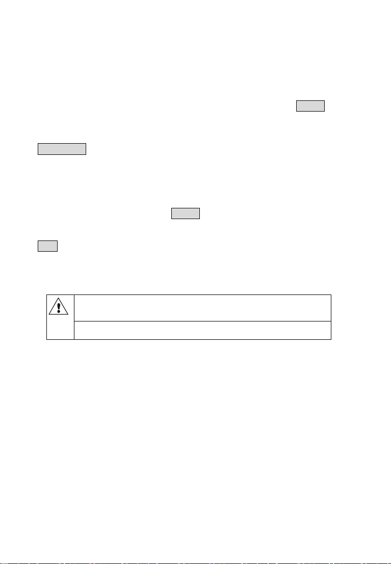
7.Simple Measurement
When select commercial use power supply system earth as auxiliary
earth electrode, it must use detector to confirm that is it the earth ground
electrode for commercial use power supply system.
It is forbidden to use this Tester to confirm earth electrode of commercial
use power supply system
This method is a simple method for measurement that does not use
auxiliary grounding rod, taking the earth electrode with the minimal existing
earth ground resistance value as auxiliary earth electrode, and connecting by
two simple testing wires (in which C, P interfaces are in short circuit). It can
make use of metal pipes, fire hydrants and other metal buried objects,
common grounding of commercial electric power system or lightning
protection earth ground electrode and others to replace auxiliary grounding
rods C, P, and pay attention to remove oxide layer on the connection point of
the selected metal auxiliary grounding object when making measurement.
Earth ground resistance simple testing wire connection is as following
figure, and refer to precision measurement for other operations.
-12-
Simple method for measurement of earth ground resistance, its reading
on Tester is the total value of earth ground resistance value of measured
grounding object and that of commercial grounding object, namely:
RE=RX+re
In which: RE is the Tester reading value;
RX is the earth ground resistance value of measured
grounding object;
re is the earth ground resistance value of common grounding
object like commercial use power system.
Then, the earth ground resistance value of measured grounding object is:
RX=RE-re
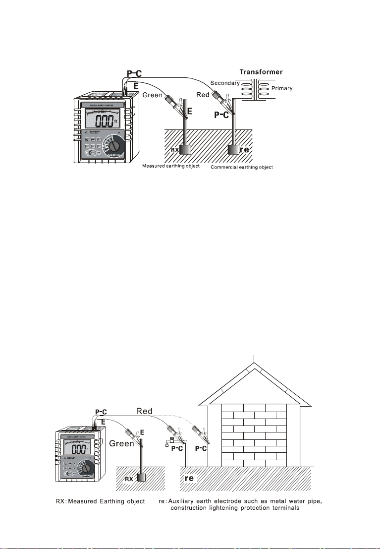
Adopting simple method for measurement of earth ground resistance
shall try to select the grounding object with low value as the auxiliary
earth ground electrode and thus the tester reading value can be more
approaching to true value. Please take precedence in selecting metal
water pipes, fire hydrants as auxiliary earth electrode when measuring,
and refer to the following figure for application.

-13-
Note
Simple method for measurement of earth ground resistance also needs
to confirm that voltage value to ground must be lower than 10V. If the
voltage value is over 10V, the measurement value of earth ground
resistance may cause error and at that time, it shall firstly cut off power
on measured grounding equipment and make resistance measurement
after the grounding voltage is decreased.
8.Backlight Control
After startup, press button to turn on or off backlight. The backlight
function is suitable to dark spot. It will default backlight turn-off for each
startup.
9.Alarm Settings
After startup, press button for a brief time to open or shut off alarm
function, press button for a long time (about 3 seconds) to enter alarm
critical value settings, press or to change current digital, press
button to move cursor and then press button to store and exit. When
measurement value is larger than alarm critical settings value and it has
opened alarm function, the Tester will flash and display icon and give out
“toot-toot-toot--”alarming sound.
10.Data Lock/Storage
Startup or after measurement, press button to lock current
displayed data, showing , icon and automatically store with serial
numbers. If storage is full, the Tester will display icon. Each group of
stored data includes maximum, minimum and average value. And then press
button to remove lock.
As shown in the left figure below: the lock measurement data is 5.1Ω, as
the 19th group of data storage.
11.Data Reading/Deletion
Startup or after measurement, press button for a longer time (over

-14-
3 seconds) to enter data reading, press or button to select reading
data group number by step value 1, press or button constantly to
select reading data group number by step value 10, press button to read
the maximum, minimum and average value of this group of data, and then
press button to exit from reading.
On reading if there is no storage data, LCD will display “- - - -”, see the
above right figure.
Under data reading status, press button to enter data deletion, press
or to select “no” or “YES”, selecting “no”and then pressing “MEM”
button for not deleting return data reading status, selecting “YES”and then
pressing “MEM”button for deleting stored data and it will show as above right
figure after deletion.
12.Data Upload
Make good connection of company with RS232 communication wire of
the Tester, switch on the Tester and run monitoring software, and if the
software displays that interface is open and the connection is successful,
then it can read the stored historical data, upload to company and preserve.
Monitoring software has the function of online real-time monitoring
and historical inquiry, dynamic display, with the maximum, minimum, and
average value indication, with alarm value settings and alarm indicator, and
the function of historical data access, reading, preserve, print and other
functions.
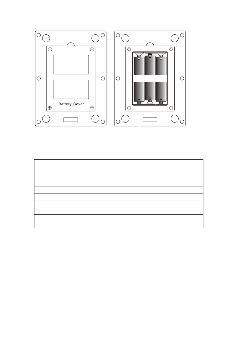
VIII. Battery Replacement
Please don’t replace battery in flammable spot
Please don’t replace battery during measurement
Pay attention to battery polarity and specification, and don’t
mix use of new and used battery to avoid damage on Tester
When the enclosure of Tester is wet, please do not open
battery cover
Please put the used batteries in appointed collection place.
1. Switch off; making sure that the Tester is under switch-off state.
2. Loosen the four screws on battery cover at the bottom of the Tester, and
open battery cover.
3.Replace new battery, pay attention to battery polarity and specification,
close battery cover, and fasten screw.
4. Switch on verification, otherwise re-operate.
-15-
IX.Accessories
Tester
1 PC
Tester Bag
1 PC
Auxiliary Grounding Rod
2 PCS
Monitoring Software Disk
1 Copy
RS232 Communication Cable
1 PC
Testing Wire
3 PCS
Simple testing wire
2 PCS
Zinc-manganese dry battery
6 PCS(R14S 1.5V)
Manual/Warranty card/Qualification
Certificate
1 Copy


Your Testing Specialist
Table of contents
Other MEWOI Test Equipment manuals


