MEWOI MEWOI-HLY200A User manual

Contact Resistance Tester
MEWOI-HLY200A
User manual
www.mewoi.com

2

1
warning
To prevent electric shock、human injuries, please read below information
carefully before using this instrument:
Only qualified person can operate this instrument
Please don’t use the instrument in wet environment
To prevent damage to this product or other product connect to this
product, or other possible danger, please use this product within
specified range.
To prevent static electricity induction of the instrument body, please
connect the mainframe with grounding before test.
because the input and output terminal、test post may with voltage,
when you plug in or pull out the test wire、power socket, may cause
electric spark, please be careful to avoid electric shock, pay attention to
human safety.
To prevent danger of fire or electric shock, please read this manual
carefully before use the instrument, and ensure each rated value and
sign of instrument are normal.
Once suspect the safety protection function of the instrument is
weaken, please put the product in non-operating state immediately, and
be sure it won’t be operated accidentally.
When the test wire connected to the electriferous terminal, please
don’t connect or disconnect arbitrarily, if the product was electriferous
accidentally, please don’t touch the exposed connection point or area.
Please check the test wire before using them. Please don’t use
defective insulation wire or wire with metal exposed. Please check the
continuity of the test wire.
Please use the power wire and connector which was matched with
the country or area’s voltage and socket.
When the cover of the instrument was open, please don’t use the
product.

2
Note to keep ventilated smooth of instrument vents, please don’t
block air vents, and avoid affecting cooling.
Please only use the spare fuse which was specified in this manual
During test, please don’t turn on or turn off the power frequently,
avoid damaging the instrument or reducing the accuracy of test results.
If any abnormal situation during test, please cut off the power
immediately
Please don’t place the product outdoor or get wet by rain, and don’t
use the product in environment with explosion gas、water vapor or
dust.
When the product working abnormal, please contacts the
manufacturer timely, and please don’t maintain by yourself.
Our company reserves the right to modify this manual, and won’t
further notice at that time. The discrepancies of product and manual please
refer to actual product.

3
CONTENT
Ⅰ、Summary.......................................................................................4
Ⅱ、Safty precautions..........................................................................4
Ⅲ、Performance features....................................................................5
Ⅳ、Technical specification.................................................................6
Ⅴ、Operation and function introduction............................................7
Ⅵ、Testing and operation method......................................................8
Appendix 1:contact (loop) resistance basic knowledge ............14
Appendix 2:circuit breaker conductive contact(loop) resistance
Standard reference value....................................................................15
Ⅶ、Standard configuration...............................................................16
After sale service...........................................................................16

4
Ⅰ、Summary
The good or bad of conductivity of breaker(hereinafter referred
to as switch) conductive circuit, play an important role in guarantee
the safety operation of switch. The conductivity performance can be
reflected by the value of conductive circuit resistance. For this reason
IEC standard and manufacturers all required testing the circuit
resistance, and also have prescribed index for the circuit resistance of
each kind switch. Before, normally use double bridge. But, because
the voltage and current value are very small, when there are
impurities between dynamic and static contact or the contact got
surface oxidation, the dispersivity of test data is larger. At the same
time, the anti-interference performance of bridge is not good, so the
national standard requires that must test with DC more than 100A.
The circuit resistance tester is a product developed by our company
which in order to meet GB50150-2006 and DL/T 845.4-2004
regulations, and it was widely used in measurements of various
switch’s contact resistance、circuit resistance, cable and wire、weld
joint contact resistance.
Ⅱ、Safety precautions
1、Operator must have common sense to operate electrical
equipment or instrument.
2、Please read operating manual carefully before use this

5
instrument.
3、The adjustment and maintenance of the instrument must be
done by specialized persons, don’t fix by yourself.
4、The instrument should avoid strenuous vibration, avoid heat
and direct sunlight.
5、This instrument was designed to test purely resistive circuits,
can not use to test inductive circuits.
6、Can’t dismantle test wire during test.
7、The grounding wire must connect correctly.
Ⅲ、Performance features
1、The test current value is big, completely conform the
national standard requirement which related to contact resistance
test.
2、The test current was came from the 100A/200A high
precision switch type constant current power supply, without
manual adjust, the test is rapid and accurate.
3、Adopt four terminal connections; effectively eliminate the
influence to the test result from resistance of test wire.
4、Test speed is fast.
5、Working long hours, equipped with overheat protection
6
circuit; the instrument is reliable and steady.
6、Easy and simple operation, light weight.
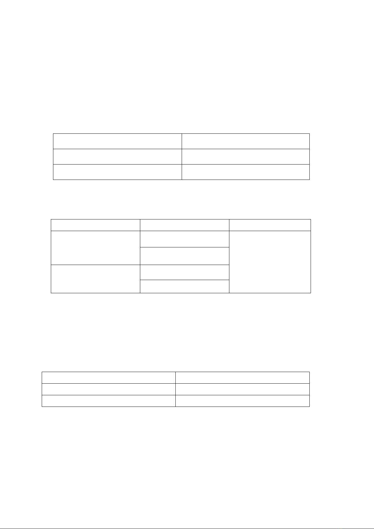
Ⅳ、Technical specification:
1、Test Current :
Model
Test Current
HLY100A
50A、100A
HLY200A
100A、200A
2、Testing range:
Model
Test Current
Testing Range
HLY100A
50A
1-1999.9μΩ
100A
HLY200A
100A
200A
3、Minimum resolution :0.01μΩ
4、Accuracy :1%±0.5μΩ
5、Power supply :AC220V±10%50Hz
6、Consumed power :
Model
Power
HLY100A
≤500W
HLY200A
≤1000W
7、Operating temperature :-20℃~40℃
9、Relative humidity :≤80%RH,non-condensate
10、Weight :

7
model
weight
HLY100A
5 Kg
HLY200A
6 Kg
Ⅴ、Instrument operation and function introduction
Contact resistance tester panel as shown in picture 1:
1、Power:Power socket and switch have fuse box and filter inside,
it’s the component to control and protect and filtering the power of
the instrument.
2、I+、I-: Refers the current output terminal, provide constant
current for testing product by specified test wire.
3、U+、U-: Refers the input terminals of test product voltage.
4、Display: show test results, contact resistance value and output
current value.
5、Reset key: instrument initialization, the instrument is in the
ready state.
6 :Instrument protective grounding terminal

8
Picture 1 Contact resistance tester panel
Ⅵ、Testing and operation method
1、Connection method: as shown in picture 2,put the specified wire
red to red, black to black, the thick current wire connect to I+、I-
terminal and tighten, the thin voltage wire connect to the U+、U-
terminal and tighten, the two clamp clamped to both ends of the
testing product.

9
Picture 2 testing connection chart
Note: the connection surface of the clamp should contact the
product reliably.
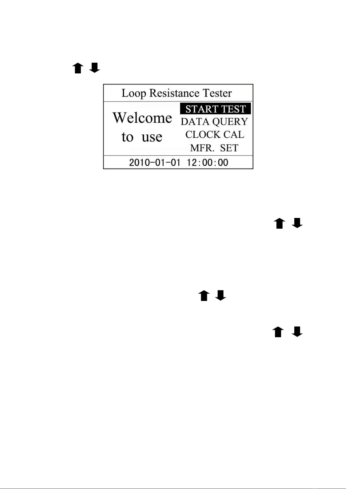
2、Start-up interface: turn on the power switch, the display will
show the interface shown in picture 3,after few seconds will
automatic skip into the main interface.
Picture 3: start-up interface
picture 4: keyboard
10
3、Main interface: the main interface shown as picture 5. Press
key choose function , press key OK enter function menu.
Picture 5: main interface
4.Test: after choose START TEST in main interface, go into the
interface of current selection as picture 6, press key
choose current, please refer to corresponding measuring range,
choose the right current. Press ESC go back to main interface,
press OK start test, at the same time remind “testing……”. Test
result shown as picture 7, press key choose PRINT or
SAVE, press ESC go back to main interface. This instrument has
function of automatically stop.. As well, press key
choose PRINT or SAVE, press ESC go back to main interface.

11
Picture 6 : interface
Picture 7
5.Data query: after choose DATA QUERY in main interface, go into
query interface as picture 8. Press key choose
function ,press key ESC go back to main interface,press key OK
execute the selected function.
Previous Next :Use to turn pages.
Print: print the test results saved in DATA QUERY.
Delete: delete all the saved test results.

12
When the data is full, there is a reminder “storage is full”. Please
press key RST go back to main interface.
picture 8
6.Clock calibration: after choose CLOCK CALIBRATION in main
interface, go into the clock calibration interface.
Key use to change the value of selected position .
Press key OK, cursor move right, when move to the last position
“second”, press key OK again, the modified time will be saved.
Press key ESC, cursor move left, when move to the first

13
position“year”, presses key OK again, the modified time will not
be saved.
7.Manufacturer setting: this option is for manufacturer to debugging
and setting, customer please doesn’t operate.
8.Reset: after finish testing, press key RST, the instrument output
current will cut off, and the displayer will go back to initial state,
and can rewiring, execute the next measurement or removal the
test wire and power wire and finish testing.
9. Temperature warning: when the temperature inside the instrument
is too high, the interface will show” Temperature warning,
Cooling now,Please wait...”,at the same time, the buzzer will
warn, at this moment should wait the instrument temperature get
back to normal, and then continue to use the product.

14
Appendix 1:Contact resistance basic knowledge
1、What is contact resistance?
Contact resistance is the additional resistance when the static contact touch dynamic
contact.
2、Breaker contact resistance was made up of which part?
Was made up of contract resistance and surface resistance of dynamic、static contact area.
3、Unqualified reasons of breaker contact resistance?
—Contact burn out when switch big short circuit current.
—When the construction adjust not good or fixed not securely, cause change stroke,
when over stroke was badly unqualified, cause contact pressure and contact area
changed.
—After adjustment and installation of breaker, not operate for a long time, cause
dynamic、static contact got surface oxidation, contact area resistance increase.
—Long-time working cause spring deformation, decrease the contact pressure.
—Mechanical wear of mechanical part after long-time working.
—For low-oil breaker, also can be the reason of unqualified acid value of insulating oil,
when it appear acid and corrode the surface. Or because of the floating impurities in oil,
and tiny carbon、metal dust between dynamic、static contact caused by switch short
circuit current, can increase the contact resistance.
4、The factors influencing resistance.
—Material property: hardness、chemical property、mechanical strength and electrical
resistivity of metallic compound.
—Contact mode: point contact、line contact、surface contact.
—Contact surface situation: when the contact surface form oxidation film(except
silver),the resistance of oxidation film is much bigger than the metal.
—Contact pressure.
—Roughness of contact surface.

15
Appendix 2:Breaker conductive contact resistance reference value
model
loop resistance of
each phase
model
loop resistance of
each phase
SN1-10
<95
DW1-60G
200
SN2-10G
75
SW1-110
700
SN4-10
50—60
SW2-110I
180
SN4-20
50—60
SW3-110
160
SN4-10G
20
SW4-110
300
SN4-20G
20
SW6-110
180—220
SN5-10
100
SW2-220
400
SN6-10
80
SW4-220
600
SN10-35
<75
SW6-220
<400
DW1-35
550
SW7-220
<190
DW1-60
500
KW1-220
400
DW3-110
1100—1300
KW2-220
170
DW2-110
800
KW3-220
110
KW1-110
150
KW4-220
130
KW3-110
45
DW2-220
1520
KV4-110A
60
DW3-220
1200
DW3-110G
1600—1800
SW6-330
>600

16
Ⅶ、Standard configuration
mainframe
One piece
specified test cable
One set
power wire
One piece
fuse
Two piece
After-sales service
1. Our company gives one year warranty for sold product. If user
wants maintenance please contact our after-sales department.
2. During warranty period if happen any following situation, we will
charge a cost price for maintenance:
1)Failure or damage caused by clash during user using or
moving the product.
2)The product was not kept properly by user, cause instrument
ooze water、affected with damp、clash or light fire and so on.
3)Failure or damage caused by maintenance from user or
other entrusted unit by user.
4)Failure or damage caused by wrong connection from user.
5)Failure or damage caused by force majeure(like fire disaster、
flood disaster、natural disaster and so on)
6)Failure or damage caused by connect to other equipment
not according to this manual.
7)Faulty product has no warranty card and unable to
determine it is within warranty period.

17
Your Testing Specialist
Table of contents
Other MEWOI Test Equipment manuals


Popular Test Equipment manuals by other brands


Bahco
Bahco BBT60A Original instructions

Alcochem Hygiene
Alcochem Hygiene UV-A MOBILE TESTER instruction manual

Myron L
Myron L ULTRAPEN PT4 quick start guide

Rohde & Schwarz
Rohde & Schwarz CMW-KM750 user manual

Keysight
Keysight P9241 SCPI Programmer's Guide

OTC
OTC 3052S PARTS LIST & OPERATING INSTRUCTIONS


