MEWOI MEWOI1500D User manual


CONTENT
WARNING....................................................................... 1
I INTRODUCTION........................................................... 3
II ELECTRICAL SYMBOLS ............................................. 5
III TECHNICAL SPECIFICATIONS ................................. 5
IV. STRUCTURE............................................................. 8
V OPERATIONS ............................................................. 9
1. POWER-ON/OFF OF HVDETECTOR ........................................................ 9
2. POWER-ON/OFF OF PRINCIPAL MACHINE...............................................10
3. TEST OF HVCURRENT.........................................................................11
4. TEST LV CURRENT ..............................................................................14
5. TEST OF CT RATIO,POLARITY..............................................................16
6. DETECTION ON PHASE SEQUENCE ........................................................20
7.ALARM LAUNCH..................................................................................20
8. DATA RETENTION AND RELEASE...........................................................21
9. DATA STORAGE ...................................................................................21
10. DATA SEARCH ...................................................................................21
11. DATA DELETION.................................................................................22

12. DATA UPLOAD ...................................................................................22
VI. SETTINGS............................................................... 22
1. SET CT RATIO .....................................................................................23
2. SET ERROR..........................................................................................23
3. SET TIME.............................................................................................24
4. SET BACKLIGHT ...................................................... 24
VII. BATTERY REPLACEMENT.................................... 24
VIII. ACCESSORIES ..................................................... 25

-1-
Warning
Thanks for purchasing MEWOI1500D Three-Channel Wireless HV
CT Ratio tester (Full Name: Three-Channel Wireless High & Low
Voltage Current Transformation Ratio Error tester for Current
Transformer). For your better use of the product, please kindly
follow the rules below:
---Read the manual carefully. The operator shall fully
understand the guidelines set forth in the manual
before conducting field tests.
---Comply with the safety rules and notices set forth in
this manual strictly.
◆The safety shall come first when using this tester in any cases,
especially, in which the voltage circuit bears the voltage of AC100V
or more.
◆The tester shall be applied connecting insulating rod, with the
hand holding on the fifth rod, in case that the voltage circuit bearing
the voltage over 600V is to be tested.
◆Operators shall have accepted the rigid training and gained
related certification for high-voltage operation before conducting
field test with this tester, due to risk of high voltage lines.
◆Take notice of characters and symbols labeled on the face board
and back board.
◆It is prohibited to operate the instrument cover and insulating
rods under moisture condensation.
◆Please don’t place or store the tester under direct sunshine, in
-2-
high-temperature and moist or dewed places.
◆Take notice of the polarities of the battery when doing
replacement; remove the battery from the tester if you expect not
to use it for a long time.
◆Disassembly and maintenance of this tester shall be only done
by authorized operators.
◆Please don’t operate testers which clips and other parts are
broken.
◆Avoid attacking clips and maintain the tester regularly. Soft cloth
(e.g. glasses cloth), moistened by clean, antirust and dehumidified
lubricant (e.g. WD-40), instead of corrosive agent or rough issues
shall be used to gently rub down the tester.
◆Stop using and mothball, then leave it to authorized organization
for handling in case that continuing use can cause safety hazard
due to the performance of the tester itself.
◆The users shall follow the user manual to do safe operation
when contacting the dangerous signs “ ” labeled on the tester
or in manual.
◆The users shall follow the manual to do safe operation when
contacting the extremely dangerous sign “ ” on the tester or
in manual.
◆It is recommended to test the insulating strength for this tester
at least one time a year, (which insulating strength should be
AC100kV/rms between HV detector and the fifth insulating rod;
and be AC1000V/rms between the shell of LV current clamp and
principal machine).

-3-
I Introduction
MEWOI1500D Three-Channel Wireless HV CT Ratio tester is a
core technological product under the long-term strategy of
professional detecting techniques research on electric power
instruments developed by MEWOI, which is specific for the on-line
measurement and detection for primary and secondary current,
transformation ratio, error, phase (group) angle difference, polarity,
phase sequence, and leaker in the high & low voltage current
transformer and the voltage transformers in distribution system
under 70KV (such as 10kV or 35kV ), and is composed of high
voltage detector, three-channel low-voltage secondary current
clamps, principal machine, high-voltage insulating rods, monitoring
software, communication link, etc. it adopts the wireless
transmission signal that is capable of penetrating wall obstacles
with a direct-line transmission distance of about 30m.
MEWOI1500D tester is widely applicable to the current detection,
abstracting-proof of electricity and field operations of transformer
substations, power plants, electrical power inspection departments,
industrial and mining enterprises, inspection station, and electrical
maintenance departments.
Current clamp: it adopts the special alloy, the latest CT technology,
and the double shielding technology for a high accuracy, stability,
and reliability during continuous monitoring in the entire year.
Principal machine: it displays four sets of current signals, CT ratio,
phase angle difference , and polarity visually in one screen
simultaneously, which memory can store 1,500 sets of data; it is
available to set the auto-save interval time to monitor leaker.

-4-
HV detector breaks the traditional structure with an automatic
opening and closing functions, it is easy to clamp or release
measured wire by pressing or pulling back insulating rods, with
the advantages of safety and time-saving. The lightweight
insulating rod is characterized by thermo stability, moisture-proof,
strong shock resistance & bending resistance high-insulation, high
flexibility and so on.
Monitoring Software: Functions such as real-time monitoring,
historical data search, accessing, browsing, saving, and printing
data available; dynamic display;
MEWOI1500D ratio tester integrates the functions of
single-channel wireless HV CT tester, HV & LV clamp current
meter, HA current remote sensor, HA leaker tester, High accuracy
clamp leaker meter, phase detector, three-channel leaker
recorder ,etc.

-5-
II Electrical Symbols
Extremely dangerous! Operators shall rigidly follow the safety rules, or
the potential electric shock can cause personal injury or death.
Dangerous! Operators shall rigidly follow the safety rules, or the
potential electric shock can cause personal injury or death.
Warning! The safety rules shall be completely followed, or personal
injury or damage to equipments can arise.
Alternating current (AC)
Direct current (DC)
III Technical Specifications
Functions
The on-line measurement and detection for primary and
secondary current, transformation ratio, error, phase
(group) difference, polarity, phase sequence, and leaker
in the three-channel high & low voltage current
transformer and the voltage transformers
Power supply
HV Detector:DC6V alkaline batteries (1.5VAAA ×4)
Principal machine: DC6V alkaline batteries (1.5V AAA ×
4) 30-hour continuous operation available
Test mode
Clamp CT, HV 1CT, LV 3 CT double- shield
Transmission
mode
High-pressure tested data transmitted through wireless
network, with a linear transmission distance of 20m;
Range
HV detector 1st: 0.1mA ~ 1000A
LV current clamp 2nd: 0.01mA ~ 10A
Resolution
HV detector: 0.1mA; LV current clamp: 0.01mA
Primary circuit
test accuracy
(23 ℃±3 ℃,
below70% RH)
0.0mA~9.99A:±1%±5dgt
10.0A~49.9A:±2%±5dgt
50.0A~199.9A:±3%±5dgt
200A~600A:±4%±5dgt
601A~1000A:±5%±5dgt
Secondary
circuit test
accuracy
0.00mA ~10A :±1%±5dgt (three-channel being
displayed in one screen) (23℃±3℃ , less than
70%RH)

-6-
CT ratio
Three kinds of transformation ratio indications :
(1)convert the transformation ratio based on the
adjustable basic value of 5A for secondary circuit
current; (2)convert the transformation ratio based on
10kV-YY of 10kV/380V, that means 1st means the
current of the line under 380V, 2nd means the
secondary circuit current of CT under the 380V, and
then calculate the ratio between the 10KV line and the
secondary circuit;
(3)the measured current ratio can be calculated by the
measured CT ratio between the primary and secondary
circuit.
Reference
Range
Reference range of transformation: 0.00A ~ 99.99A, the
default secondary circuit current is transformed to 5A;
Range of Ratio
error
(F.Er)
0.0% ~ 9.9%, the error between the measured CT ratio
and the preset CT ratio
Range of CT
ratio
0000~9999/0.0A~9.9A
Range of Ratio
error
0.0%~9.9%, the principal machine can sound a alarm
of “beep - beep –beep” if the measured value is more
than the preset error.
Phase polarity
Symbol indicated for in-phase positive polarity
Symbol indicated for in-phase negative polarity
Indication of
Phase
Sequence
Cursor in clockwise rotation and “Positive Phase”
indicated for positive phase sequence
Cursor in counterclockwise rotation and “Negative
Phase” indicated for negative phase sequence
Indication of
Error
Symbol “Error” indicated if the tester can’t identify the
phases, polarity, and phase sequence properly;
Data Storage
1500 sets of dada memory; press the Left arrow key to
select data, and to save and auto-number the selected
data (the good condition of data available under
power-down or battery replacement)
Automatic
Recording
Interval Time
From 00 minutes to 99 minutes, the tester stops
automatic record if being set to 00 minutes; the principal
machine doesn’t shut down automatically if being set
from 01 minutes to 99 minutes.

-7-
Sampling rate
3 times / sec
Shift
Full-automatic shift
Dimensions
Principal machine:W75mm ×H170mm ×T30mm;
HV detector: W 76mm ×H 255mm ×T 31mm;
LV current clamp: W 70mm ×H115mm ×T 38mm;
Clamp Size
HV detector clamp: φ48mm
LV current clamp: 25mm ×30mm
Voltage
Less than 70kV voltage for line test(operation by being
connected to 5 insolating rods required)
Display Mode
LCD: 128dots ×64dots;
backlight available for dark areas
LCD Size:
44mm ×27mm;
Data Retention
Press the Left arrow key to retain the data ; press the
Left arrow key to cancel retention if the symbol “HOLD”
displays;
Data Search
Press the MEM key and the Arrow key to search data;
Overflow
Display
Overflow available if being out of range: the symbol “OL
A” displayed;
Zero-signal
indication
The symbol “---” is shown if the principal machine can’t
receive the signal from the HV detector;
Backlight
Control
Available; ON / OFF means to open /close the backlight;
Alarm prompt
The principal machine can sound an alarm of “beep -
beep –beep” if the measured value is more than the
preset error. and press the Right arrow key to launch or
stop the alarm function;
Auto power-off
Automatic power-off available after about 15 minutes as
of starting;
Battery voltage
The low- voltage symbol is displayed to remind user to
replace the battery if the battery voltage is lower than
4.8V;
Weight
Principal machine:240g (including batteries)
HV detector: 335g (including batteries)
LV current clamp: 150g ×3
Total weight: 10kg (including instrument box and the
insulating rods)
Requirements
on Interferences
No strong electromagnetic interference; no interference
from 433MHz and 315MHz channel

-8-
Operating
temperature
and humidity
-25℃~45℃; less than 80%Rh
Storage
temperature
and humidity
-10℃~60℃; less than 70%Rh
Insulating rod
size
Outer diameter φ32mm, inner diameter φ24mm, 1m
/piece, 5 pieces
Lead length of
LV current
clamp
2 m / Piece
Dielectric
strength
AC100kV/rms between HV detector cover and the 5th
insulating rod; the AC1000V/rms between the principal
machine and the LV current clamp shell between
Structure
Anti-leak type II (HV detector)
IV. Structure

-9-
1. HV detector clamp (including the boot sectors)
2. HV detector booting indicator
3. POWER key on HV detector
4. Connector of insulating rods (φ24mm)
5. RS232 interface, for data upload to computer
6. POWER key on principal machine
7. MEM key and arrows keys
8. LV current clamp CT1 Interface
9. LV current clamp CT2 Interface
10. LV current clamp CT3 Interface
11. Principal machine LCD displayer
12. LV current clamp output plug
13. LV current clamp clips (3 pieces)
14. LV current clamp leads
15. Insulating rods (5 pieces)
V Operations
Check if any damage exists for each part
before operating the tester; it can be put into
use only after being qualified.
Install the battery according to the
requirements set forth in the manual.
1. Power-on/off of HV detector
Press the POWER key to power on the HV detector, and the
POWER indicator lights, the HV detector begins to detect
automatically, and transmits the tested data to the principal
machine by wireless network. The HV detector can power-off
automatically when the POWER indicator flashes continually after
about 15 minutes as of booting, and the detector can shut down
automatically to save the battery power, after the POWER indicator
flashes for 30 seconds. When the POWER indicator flashes

-10-
continually, press the POWER key to make HV detector in
continuous running, and then press the POWER key again to
power off.
2. Power-on/off of principal machine
Press the POWER key to power on, then LCD begins to display,
the principal machine enters the test and receiving mode after a
normal booting (see below), 1st means the measured data of the
primary circuit on HV terminal, 2nd means the measured data of
the secondary circuit on LV terminal, F. Er means the error
between the measured CT ratio and preset CT ratio, R, S, and T
means the three phases respectively, and the data measured by
LV current clamps of CT1, CT2, and CT3 can be displayed on the
position of R, S, and T on screen respectively. the LCD can display
the symbol “- - -” if the principal machine doesn’t receive the signal
from primary circuit; the principal machine can detect the phase
and polarity firstly, if receives the data of the primary and the
secondary circuit normally, the primary circuit currents are
correspondingly visible on the phases of R, S, and T, both the error
and polarity can be displayed on the upper left corner of LCD. If the
symbol “Err” displays on the upper left corner of LCD display, it is
not available to detect the polarity properly, and the measured
currents of the primary circuit remain being displayed on the
R-phase.

-11-
The LCD flashes continually to prompt the soon power off after
about 15 minutes as of booting, and the principal machine can shut
down automatically to save the battery power, after the LCD
flashes for 30 seconds. When the LCD flashes continually, press
the POWER key to make the principal machine in continuous
running, and then press the POWER key again to power it off
3. Test of HV current
High voltage, very dangerous !Only qualified
personnel after training could conduct operation
on it. The operator should obey safety
regulations; otherwise there can be the danger of
electric shock resulting in personal injury or
casualty.
Only when all of the five insulating bars are
connected, can the high voltage line be detected,
otherwise there may be the danger of electric
shock resulting in personal injury or casualty.
Dangerous! It is prohibited to measure high
voltage line above 70V; otherwise there can be
danger of electric shock resulting in personal
injury or casualty.
Dangerous! Prohibited to detect the high current
wire above 1000A.
Prior to the detection, have the insulation bars
connected properly; finally have the detector
connected, for avoidance of any ground impact on
the HV detector.
Nothing but the special-made insulation bars
could be connected to HV detector.
After the detection, collect the insulating rod in
slant direction; first remove the HV detector, then
the insulation bars for the avoidance of ground
impact on HV detector.

-12-
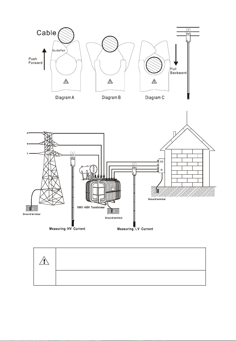
If the high voltage detector can be properly connected with 5
insulating rods and starts normally, please set the lead at the
center of boot sector on detector clamp (as shown in Figure A).
The boot sector on HV detector is perpendicular to the lead, Push
forward the insulating rod, the lead is clamped by the high voltage
detector which starts detecting and feedbacks to the principal
machine. Principal machine enters the detection and data
collection state after its normal starting up, If the principal machine
receives the signal sent by the high voltage detector, the primary
circuit current of high voltage end can be shown on R phase, If the
principal machine shows that the primary circuit current value is
“OL”, it is indicated that the primary circuit current exceeds the
upper limit of the high voltage detector. Push the insulating rod
backward, the high voltage detector is disconnected with the lead
(As shown in figure C). Please do keep the boot sector
perpendicular to the lead while removing.
The principal machine can detect the phase (group) differences
between the primary circuit and the secondary circuit firstly if
receives the signal from the primary circuit, and then determine the
polarity under in-phase; and the measured currents of the primary
circuit remain being displayed on the R phase if different phases;
the primary circuit currents are correspondingly visible on the
phases of R, S, and T, under in-group.
-13-
Notice: please take the instrument away from
the wire after the detection is finished for a
safe operation.
It is available to measure HA current/leaker by
the tester
-14-
4. Test LV current
High voltage, very dangerous !Only
personnel after training can conduct
operation on it. The operator should bear
safety regulations in mind; otherwise there
can be the danger of electric shock resulting
in personal injury or casualty.
Testing the LV current by the HV detector
available
Testing the 4 circuit currents or leakers by
the HV detector available
It is prohibited to insert LV current clamp for
an accurate measurement.
It is prohibited to use low voltage current
clamps to detect high voltage wire above
600V or 10A; otherwise there can be the
danger of electric shock resulting in
personal injury or casualty.
1) Connect three LV current clamps to the corresponding principal
machines, power on the machine into the test mode.
2) Vise the measured wires with the LV current clamp (Note: the
clip should be fully closed), observe the readings of the secondary
current, if the machine displays the symbol “OL A” while detecting
the secondary current, it is indicated that the measured secondary
current overflows the preset maximum of the LV clamp in the tester,
it is recommended to use the HV detector for its measurements.
The tester is capable of detecting three-channel or four-channel
current /leaker, please operate based on actual requirements.

-15-
3) Reference Diagram:
①Recording the circuit current
②monitoring leakers from equipment
③Detecting cable leakers in wall
④Detecting leaker from grounding wire

-16-
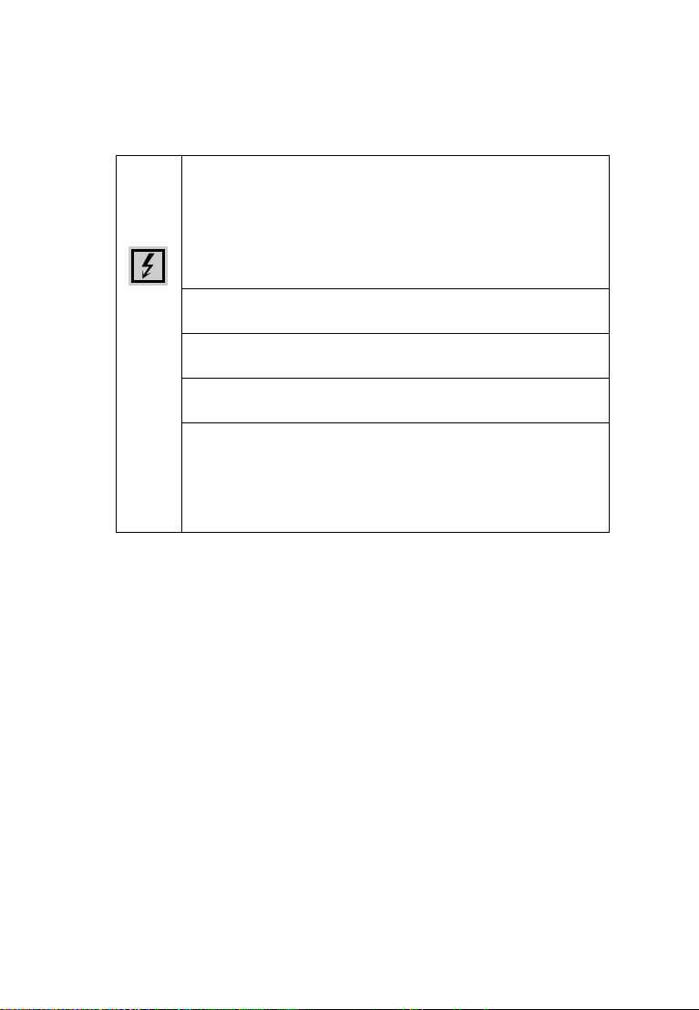
Clamp live wire and null line at the same time, to
measure leaker (note: total 2 wires)
Clamp the earth wire to measure the leaker of
earth wire of the tested electric equipment(note:
single wire)
Clamp the main wire to measure the total current
of main wire of the tested electric equipment(note:
single wire)
Use high voltage detector to measure the current
on low voltage wire in the places where its
indication is not easily accessible.
Please preset the automatic recording interval time for a
long-term record and monitoring of the current or leaker the
automatic recording interval time is available from 01 to 99 minutes,
it is recommended to switch off the backlight in order to reduce the
consumption of battery.
5. Test of CT ratio, polarity
【1st】: the current detected by single-channel HV
detector, the primary current for CT.
【2nd】: the current collected by three-channel LV
current clamp; the secondary current for CT.
【F.Er】:The error between the measured CT ratio and
the preset CT ratio.
【R, S, T】: indications of three phases; the in-phases
indicated on the same wire.
【】:the In-phase positive polarity; the phase-angle
difference is about from 0°to 25°or from 335°to 360 °.
【】:The in-phase negative polarity, the phase
angle difference is about from 155 °to 205 °; the
in-phase negative polarity means that the primary
current polarity is opposite to the secondary current
polarity under in-phase voltage; the current clamp
is oppositely operated between the primary current
and the secondary current. (Both the obverse side of
HV detector and the obverse side of LV current clamp
are the in-phase terminals for current input).
Table of contents
Other MEWOI Test Equipment manuals


