MEWOI MEWOI-UCT-C User manual

Transformer Turn Ratio Tester
MEWOI-UCT-C
User Manual
www.mewoi.com


CONTENT
Warning................................................................................................ 1
I . Brief Introduction.............................................................................. 3
II. Main Features .................................................................................. 3
III. Technical Specification.............................................................. 4
IV. Structure.................................................................................... 5
V. Operating Interface and Operating Method.............................. 7
1. Power On/Off.....................................................................................7
3. Single-phase transformer or PT transformer measurement..........9
4. Measurement of three-phase transformer .....................................11
5. Nameplate Guess Instructions.........................................................12
6. Store andAccess data.......................................................................13
7. Time Setting.........................................................................................14
VI. Operation Examples................................................................ 15
VII. Instrument Self-Checking........................................................ 17
VIII. Battery Charging Instructions.................................................. 18
IX. Accessories............................................................................. 19
X. Matters Needing Attention....................................................... 19

-1-
Warning
Thanks for your purchase of Transformer Turn Ratio Tester
MEWOI-UCT-C of our company. In order to make better use of this
product, please make sure to:
——Read this manual in detail and the operator must
totally understand this manual and be in proficient in
operation of this meter before making test on spot.
——Strictly comply with the security rules and notice
items listed on this manual.
Before use, make sure the instrument is in good condition and
without breakage. In any case, the instrument shall be used
with particular attention to safety.
This instrument can be used indoors and outdoors, but should
avoid rain, corrosive gas and excessive dust.
The instrument should avoid severe vibration.
Please do not put or store this meter in the place of high
temperature, with moisture, with frozen dew or with direct
daylight irradiation for a long time.
The yellow, green and red of the test clamp correspond to the
three-phaseA, B and C of the transformer respectively.
Please don’t use it If the instrument or accessories damaged.
Don’t misconnect the high voltage end cables and low voltage
cables.
When measuring single phase transformer, only yellow and
green clamps are used, while red clamps are suspended.
It must be operated by qualified staff that has the authorization
on tearing down or repairing this meter.
For the reason of this meter, in case that any danger may
occur if continue to use it, stop using it immediately and seal it
up for keeping at once, which shall be dealt with by qualified
authorization agency.

-2-

-3-
I . Brief Introduction
The Preventive Test Rules of the State Ministry of Electricity
require that the transformer be tested periodically for turn-to-turn
ratio or voltage ratio, including semi-finished products and finished
products in the production process, transformers before putting
into operation and during the operation of the power system. The
traditional variable-ratio bridge is complicated to operate and its
reading is not intuitive. It needs necessary conversion, and the test
results only reflect one-phase ratio. MEWOI-UCT-C Transformer
Turn Ratio Tester overcomes the shortcomings of the traditional
bridge test, completes the three-phase ratio test at one time, has
fast test speed and high accuracy, and greatly improves the test
efficiency.
II. Main Features
1, Wide test range: 0.9-10000.
2, Fast test speed, can complete the single phase test in 10
seconds.
3, 240*128 color LCD display, the interactive interface is
more intuitive
4,Wide suitable types of transformer, with Ζ shape coupling
transformer test
5, With blind measurement of turn ratio, automatically group
testing functions, tap position test function.
6, Non-power Clock and Date Display, data storage function
(can store 50 sets of test data).
7,Perfect protection function, reverse connect protection
function, high and low voltage transformer inter-turn short
circuit protection function.
8, Transformer short-circuits and inter-turn short-circuits
protection function.
9, Printer output measurements, English menu display, color
LCD.

-4-
10,Both AC and DC power supply methods are available,
can be used with or without city power.
11, Small size and light weight.
III. Technical Specification
Measure Range
0.9~10000
Accuracy
0.1%±2 words (below 500);
0.2%±2 words (500~2000);
0.3%±2 words (2000~4000);
0.5% ±2 words (4000 or more).
Resolution
Minimum 0.0001.
Output voltage
160v/10v (automatic selection).
Working power
AC: External AC power supply is required,
AC220v ±10%, 50Hz.
DC: With Built-in Rechargeable Lithium battery,
No need for external power supply.
Working
Temperature
–10°C ~ 40°C.
Relative
Humidity
≤85%, no condensation
Accessories
Host:1set,High Voltage end test cables, Low
voltage end test cables, Self-checking wires,
Power Cord, Printing Paper, User Manual

-5-
IV. Structure
1. Instrument switch: Select the power supply mode of the
instrument and start it.
-:Selection ofAC power supply mode and start-up;
○:Instrument shutdown;
=:Selection of DC power supply mode and start-up.
2. AC~220V:Power Socket; please connect AC power supply AC
220V + 10%, 50HZ. Socket with fuse.
3. Communication interface: Reserved interface.
4. L-V port: The test lines of yellow, green and red are connected
to the low-voltage a, b and c three-phase terminals of the
transformer.
H-V port: The test lines of yellow, green and red are connected
to the high-voltage a, b and c three-phase terminals of the

-6-
transformer.
5. Display: 240×128 dot matrix LCD with led backlight, display
operation menu and test results.
6. Battery power indicator: When choosing DC mode of operation,
display the remaining power of instrument battery.
7. Buttons:
1) F1,F2 Function Key: Indicate different functions according to
interface prompt during instrument operation
2) Reset Button: Press this button to reset the whole machine
and return to its original state.
3) OK Button: Please refer to: V. Introduction of interface and
operation method
4) Back Button: Please refer to: V. Introduction of interface and
operation method
5) UP Button: Move the cursor up and operate according to the
display prompt during the use of the instrument
6) Down Button: Move the cursor up and operate according to
the display prompt during the use of the instrument
7) Left Arrow: Move the cursor up and operate according to the
display prompt during the use of the instrument
8) Right Arrow: Move the cursor up and operate according to
the display prompt during the use of the instrument
8. Printer: Print test results.
9. The instrument grounding column is used for the
instrument grounding to protect the personal safety of users

-7-
and the instrument.
10. Charging port: When the instrument shows that the battery
power is low (not less than 10%) or when the instrument is not
used for a long time, the battery of the instrument should be
charged through the charging interface.
11. DC indicator: Indicator lights on when DC mode is adopted.
The indicator is green to indicate normal and show faults in
red.
Low Voltage End: The yellow, green and red of the test clamp
correspond to the three-phase A, B and C of the transformer low
voltage end respectively.
V. Operating Interface and Operating Method
Please check all parts of the meter carefully
before usage, to see whether there is any
damage. And make sure no damage before
usage.
1. Power On/Off
(It is strictly forbidden to use generators to provide AC current.
Otherwise, the measurement data may be inaccurate, if there is no
other power source and the battery of the instrument is insufficient,
the AC power provided by the generator can be used as the
charging power source. While charging the instrument, select the
DC power supply to work.).
-8-
AC or DC power supply mode can be selected to supply power to
the instrument,
AC power supply mode: set the instrument switch to the "-" position
(AC position), and the instrument is turned on.
DC power supply mode: set the instrument switch to the "="
position (DC position), and turn on the instrument.
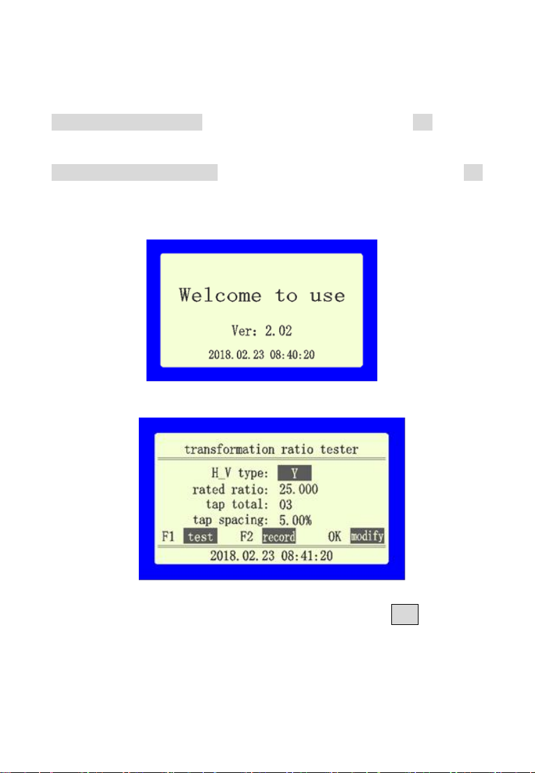
When the instrument is turned on, the screen displays as below:
After that, the initial interface is displayed as shown below:
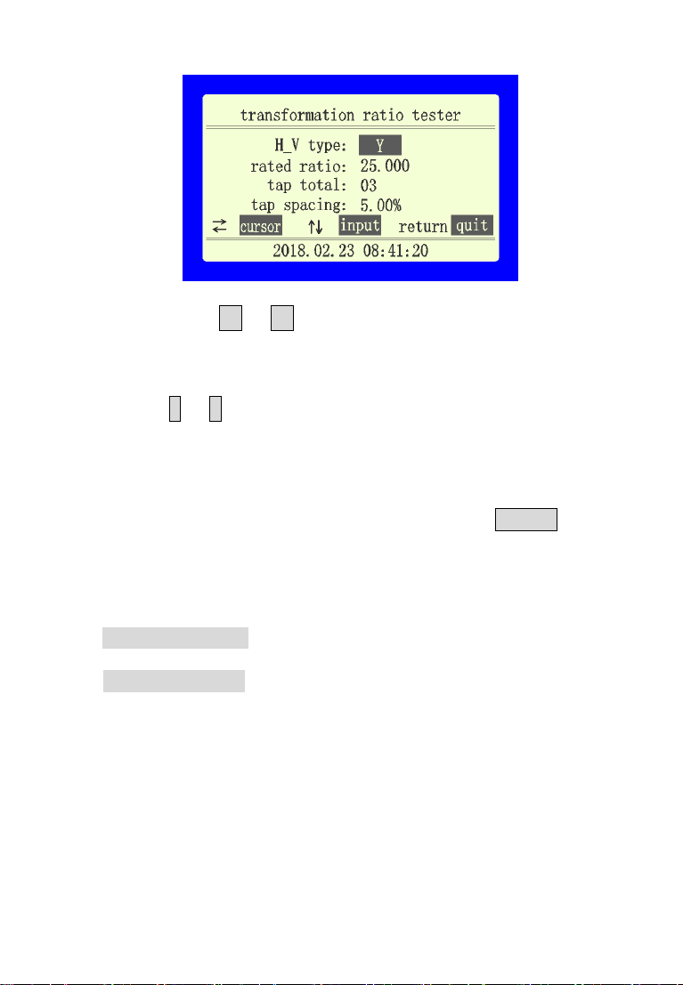
2. Parameter Modification
If you need to modify the parameters, press the OK button to
enter the parameter modification interface, as shown below:
-9-
By pressing the ←or →button, the cursor can move in circles
between the parameters, and it can move the cursor to the
parameters that need to be changed.
Press the ↑or ↓button, Can change the current
parameters ,can change the high-voltage mode. The selected
items include "Y", "D", "single", "Z". You can choose "single".
When testing, you can measure single-phase transformer or PT;
when the cursor is in other position, you can change the value of
the number; after modification, you can press the Return key to
confirm and exit.
3. Single-phase transformer or PT transformer measurement
High voltage end: The yellow and green clamps correspond to
the A, X of the transformer high voltage end respectively.
Low voltage end: The yellow and green clamps correspond to
the a, x of the transformer low voltage end respectively.
As Shown Below:
-10-
Press the OK button to modify the parameters, the high voltage
mode selects “Single”,other modifications based on actual
values.
After parameter modification is completed, press the Return
button to exit the modification interface. After confirming the
connection is correct, press the F1 button to test and show the
"Testing" and the test results later, as shown in figure below (in
this manual, the test results are only examples, the actual
values vary according to the actual situation in the field):

-11-
Press F1 button to "retest" and F2 button to "Save" ,press Print
button to print test results.
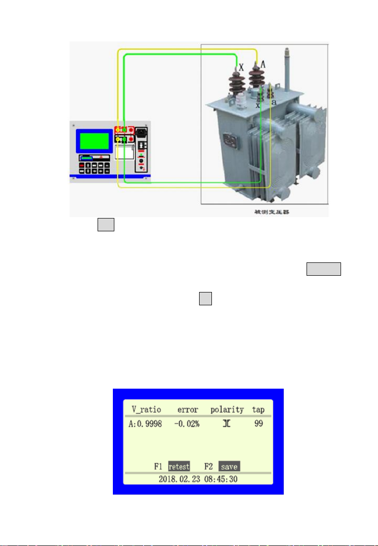
4. Measurement of three-phase transformer
High voltage end: The yellow, green and red clamps
correspond to the A, B,C phase of the transformer high voltage
end respectively.
Low voltage end: The yellow, green and red clamps
correspond to the a, b, c phase of the transformer low voltage
end respectively.
As Shown Below:
Note:If the connection group has neutral point, the neutral
point would not be connected, and the measurement data are
displayed according to the connection group without neutral
points (e.g. DYn11, the measurement result is shown as
DY11).
After connecting the clamps, display the initial interface, press
the OK button to modify parameters, select the correct
high-voltage mode, and modify other values according to the
actual value.After that, press Return button to exit the
modification interface..After confirming that the connection is

-12-
correct, press the F1 button to test and show "testing…" and
the test results displayed later, as shown in the following
figure:
Press F1 button to "retest" and F2 button to "store" ,press Print
button to print test results.
5. Nameplate Guess Instructions
If the nameplate parameters of three-phase transformer
are not clear, the instrument can accurately measure the ratio
and group number of transformer, but cannot accurately
measure the connection type, tapping position and other
parameters. The operation and description are as follows:
the high and low voltage windings of three-phase transformer
are connected to the high and low voltage terminals of the
instrument in sequence, respectively. Turn on. Select the F1 to
test directly in the initial interface and showing “Testing…”. The
test results are shown as follows:

-13-
Note: At this time, only the variable ratio and group number are
accurate. Because other parameters are not clear and
accurate values cannot be set, the turn ratio, error, tap value
and connection mode displayed are not accurate data and
cannot be used as reference. If the high voltage mode is
known, the actual connection group can be measured.
6. Store and Access data
After the data test is completed, press F2 to store the current
test results.
If you need to access the historical data stored in the

-14-
instrument, press the F2 button in the initial interface, the
screen will display as shown below:
Press UP or Down to turn the page, press Print button to
print the current data, press F1 key to delete the current
record, press F2 button to delete all records.
7. Time Setting
In the initial interface, press the Return button to enter the time
modification interface, as shown below:
Press the Left or Right key Change the cursor position, press the
-15-
UP or Down key to modify the number, press the OK
button to exit after the modification, and return to the initial
interface.
VI. Operation Examples
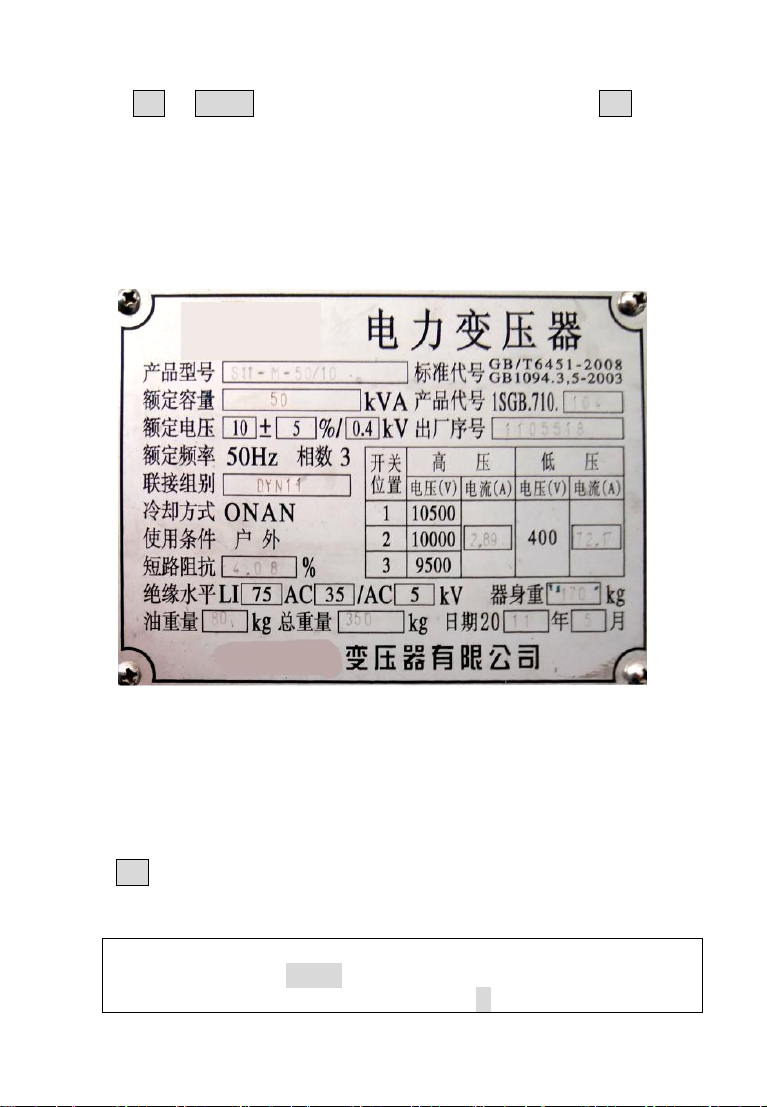
The three-phase transformer brand data is as follows:
Wiring according to the three-phase transformer wiring method
(Please refer to the measurement of V.4 three-phase
transformer).
Turn on and display the initial interface. Modify the parameters
according to the data on the transformer nameplate; Press the
OK key to enter the parameter modification interface:
1, Modify the high voltage mode: the nameplate shows the
connection group: dyn11,
Then modify the high voltage mode to: D.

-16-
2,Rated transformation ratio: (according to the middle position
of the high voltage end: 2 tap) The high voltage end voltage
value is 10000, the low voltage end voltage is 400, and the
rated transformation ratio is calculated to be
10000/400=25.Input rated ratio 25;
3, Total number of taps: The switch position shows three high
voltage values of 10500,1000,9500, so there are 3 taps
4, Tap spacing: (10500-10000) / 10000 = 5%.
After the input is complete, press the Return key to confirm and
return to the main menu, as shown below:
Press the F1 key to start the measurement. The measurement
results are shown in the figure below:

-17-
You can press F1 to retest, press F2 to store the data, press
Print to print data, Reset returns to the main menu.
VII. Instrument Self-Checking
If the user suspects that the instrument is malfunctioning or that the
test results are inaccurate, the instrument can be self-checked with
the standard short wiring equipped with the instrument.
Standardizers are shown as follows:
Connect the standard short wiring to the terminals of the
instrument as follows:
After power on, the high voltage mode displays: Y, press F1 to test,
the test result shows the following figure:
Table of contents
Other MEWOI Test Equipment manuals


Popular Test Equipment manuals by other brands


Alcoscan
Alcoscan ACE AL2600 operating manual

Dwyer Instruments
Dwyer Instruments CSG user guide

PIE Calibrators
PIE Calibrators PIECAL 322 operating instructions

Klein Tools
Klein Tools NCVT-1XT operating instructions

Gossen MetraWatt
Gossen MetraWatt METRISO C Short-form operating instructions

SUNWE
SUNWE DT-2299 Operation manual


