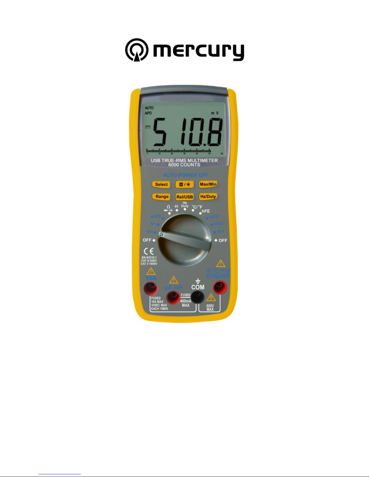
Mercury MTTR01 User manual

Item ref: 600.104UK
MTTR01
TRUE RMS DIGITAL MULTITESTER
WITH USB INTERFACE
User Manual

MTTR01 User Manual
Please read this manual thoroughly and
ensure all contents are fully understood
before using the apparatus.
WARNING
To avoid possible electric shock or personal injury, and to avoid possible
damage to the tester or to the equipment under test, adhere to these
following rules:
Before using the tester inspect the case. Do not use the tester if it is
damaged or the case (or part of the case) is removed. Look for cracks
or missing plastic. Pay attention to the insulation around the
connectors.
Inspect the test leads for damaged insulation or exposed metal.
Check the test leads for continuity.
Do not apply more than the rated voltage, as marked on the tester,
between the terminals or between any terminal and grounding.
The rotary switch should be in the right position and no changeover of
range shall be made while measurement is conducted to prevent
damage.
When the tester is working at an effective voltage over 60V in DC or
30Vrms in AC, special care should be taken for there is danger of
electric shock.
Use the proper terminals, function, and range for your measurements.
Do not use or store the tester in an environment of high temperature,
humidity, explosive, flammable, damp or of a strong magnetic field.
The performance of the tester may deteriorate after being exposed to
any of these elements.
When using the test leads, keep your fingers behind the finger guards.
Disconnect circuit power and discharge all high-voltage capacitors
before testing resistance, continuity, diodes.
Replace the battery as soon as the battery indicator appears. With a
low battery, the meter may produce false readings that can lead to
electric shock and personal injury.

MTTR01 User Manual
Remove the connection between the testing leads and the circuit being
tested, and turn the meter power off before opening the meter case.
The internal circuit of the meter shall not be altered at will to avoid
damage of the meter and any accident.
A soft cloth and mild detergent should be used to clean the surface of
the tester on a regular basis. No abrasive and solvent should be used
to prevent the surface of the tester from corrosion or damage.
The tester is suitable for indoor use only.
Turn the tester power off when it is not in use and take out the battery
when not using for a long time. Check the battery regularly; replace the
battery immediately if any signs of leaking appear. Battery acid will
damage the tester.
General Specifications
Max display: LCD (6000 count) 64 x 43mm
Polarity: Automatic, indicated minus, assumed plus
Measure method: double integral A/D switch implement
Sampling speed: 2.5 times per second
Over-load indication: “OL” is displayed
Operating temperature: 0ºC to 40ºC, at <75%RH
Storage temperature: -30ºC to 60ºC, at <85%RH
Power: 9Vdc (1 x PP3 battery supplied)
Low battery indication: “ ”
Display resolution: 6000 counts
Resistance: 600Ω to 60MΩ
Capacitance: 40nF - 4000µF
Frequency: 9.99Hz - 9.99MHz
Test temperature: -20°C - 1000°C
Duty cycle: 5% to 95%
Dimensions: 188 x 81 x 48mm
Weight: 420g (including battery)

MTTR01 User Manual
Layout:

MTTR01 User Manual
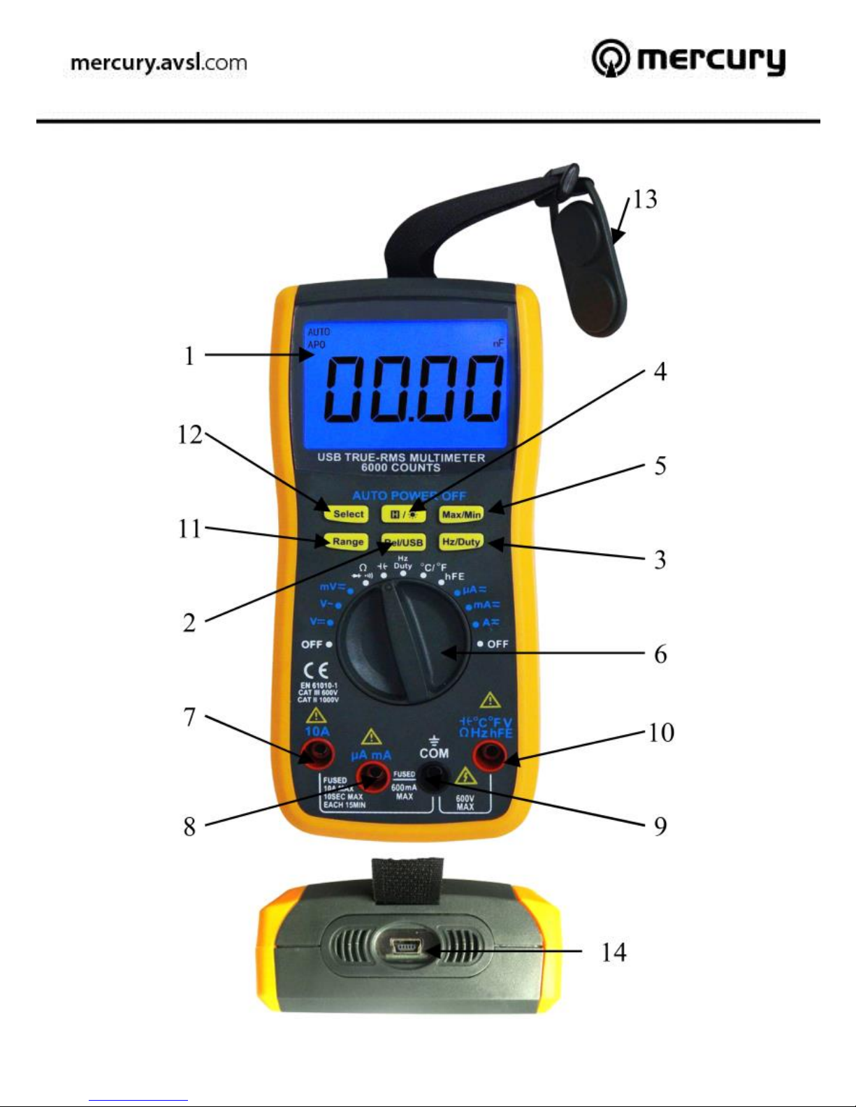
1. LCD Display, maximum reading of 5999.
2. Relative and USB mode switch. Press to switch between auto
reading mode “auto” and relative mode “ ”. Press and hold for 2
seconds to switch between USB mode “USB” and auto power off
mode “APO”.
3. Hz/Duty display, when measuring AC voltage or current, press to
display between the frequency and duty cycles of the measuring
signals.
4. “ ” Press this button to data hold the display and press again
to release data. Press and hold for 2 seconds to toggle the back
light on for 10 seconds.
5. “Max/Min” Press this button to display the maximum and
minimum reading from the moment this button is pressed. Press
and hold this button for 2 seconds to exit Max/Min display mode.
6. Function/Range switch for selecting different measuring ranges
and also serves as an ON/OFF switch. To preserve battery life,
please ensure the range switch is turn to OFF position when not
in use.
7. “10A” Probe socket, socket for the positive (red) probe when
measuring current between 400mA to 10A.
8. “uA/mA” Probe socket, socket for the positive (red) probe when
measuring current below 400mA.
9. “COM” Probe socket, socket for the negative (black) probe.
10. “Positive” Probe socket, socket for the positive (red) probe for
measuring everything apart from current.
11. “Range” switch, when measuring voltage, current, capacitance or
resistance, pressing this button with disengage the auto range
function and allow you to manually set the displaying range.
12. “Select” has following functions:
-When measuring signal with combined AC+DC, pressing this
button will allow the AC and DC to be measured separately.
-To switch between measuring function of resistance,
continuity and diode.

MTTR01 User Manual
-To switch between displaying Fahrenheit and Celsius when
measuring temperature.
-Press and hold this button when switching the meter on to
disable the auto power off function, this allows the meter to
stay on standby unless manually switched off.
13. Strong magnet that allows meter to be attached to any iron/steel
surface, in case both hands are required to take the
measurement.
14. Mini USB socket at the bottom of the unit to connect to a PC.
For testing transistors and capacitors, the measuring adaptor supplied
should be connected as below. The two square sockets on the top are for
testing capacitors and the 6 smaller sockets at the bottom are for testing
the PNP and NPN type transistors.

MTTR01 User Manual
LCD Display
These signs and symbols indicate:
1. Duty cycle is selected
2. Temperature measurement is selected and measuring in
Fahrenheit.
3. Temperature measurement is selected and measuring in Celsius.
4. Transistor testing mode is selected.
5. Continuity testing mode is selected, use “Select” button to
choose between resistance measuring, diode testing and
continuity testing.
6. Diode testing mode is selected, use “Select” button to choose
between resistance measuring, diode testing and continuity
testing.
7. Relative mode is selected, use “Rel/USB” button to select
between auto range mode and relative mode.
8. USB mode is selected; meter is now sending live readings out
through the USB output to connected PC.
9. Data hold, press “ ” to resume live reading.
10. Auto Range mode is selected, use “Rel/USB” button to select
between auto range mode and relative mode.
11. Auto power off mode, meter will automatically switch off when it
is not in use.
12. Displays the maximum reading from the moment the Max/Min
function is enabled.

MTTR01 User Manual
13. Displays the minimum reading from the moment the Max/Min
function is enabled.
14. Currently measuring DC range.
15. Negative reading.
16. Currently measuring AC range.
17. Low battery indicator; replace battery immediately when this sign
is shown to avoid false reading that may lead to electric shock.
18. Bar graph.
The bar graph on the bottom of the LCD display is the analogue display of
the reading when measuring voltage, current or resistance. The length of
the bar is proportionate to the 0-5999 digital count above it. The bar graph
has a sampling rate 10 times higher of the digital number display, this
make it ideal for observing measurements with rapid changes.
Technical Specifications
This meter has been calibrated in the factory and accuracies of following
are guaranteed for 1 year at 18ºC to 28ºC and less than 75% RH.
DC Voltage
RANGE
RESOLUTION
ACCURACY
60mV
10uV
± (1% of rdg + 7D)
600mV
0.1mV
± (0.8% of rdg + 5D)
6V
1mV
± (0.5% of rdg + 5D)
60V
10mV
600V
0.1V
± (0.8% of rdg + 5D)
Input Impedance: >100MΩ for 60 and 600mV range, 10MΩfor 6, 60 and
600V.
Overload Protection: 600V

MTTR01 User Manual
AC Voltage
RANGE
RESOLUTION
ACCURACY
60mV
10uV
± (2.0% of rdg + 10D)
600mV
0.1mV
± (1.6% of rdg + 10D)
6V
1mV
± (1.5% of rdg + 10D)
60V
10mV
600V
0.1V
Input Impedance: >100MΩ for 60 and 600mV range, 10MΩfor 6, 60 and
600V.
Frequency Range: 40Hz ~ 400Hz
Overload Protection: 600Vrms
Reading: True rms
Max. Input voltage: 750Vac rms
DC Current
RANGE
RESOLUTION
ACCURACY
Remark
600uA
0.1uA
± (1.0% of rdg + 7D)
Auto range
6000uA
1uA
60mA
0.01mA
600mA
0.1mA
6A
1mA
± (1.5% of rdg + 7D)
10A
10mA
Overload Protection:
mA: F0.4A/600V fuse
10A: F10A/600V fuse (for measurement >5A, duration need to be less than
10 sec and use no more than once every 15 min)

MTTR01 User Manual
AC Current
RANGE
RESOLUTION
ACCURACY
Remark
600uA
0.1uA
± (2.0% of rdg + 7D)
Auto range
6000uA
1uA
60mA
0.01mA
600mA
0.1mA
6A
1mA
± (2.5% of rdg + 7D)
10A
10mA
Overload Protection:
mA: F0.4A/600V fuse
10A: F10A/600V fuse (for measurement >5A, duration need to be less than
10 sec and use no more than once every 15 min)
Frequency Range: 40Hz ~ 400Hz
Reading: True rms
Resistance
RANGE
RESOLUTION
ACCURACY
Remark
600Ω
0.1Ω
± (1.0% of rdg + 5D)
Auto range
6KΩ
1Ω
± (0.8% of rdg + 5D)
60kΩ
10Ω
600kΩ
100Ω
6MΩ
1kΩ
± (1.5% of rdg + 5D)
60MΩ
10kΩ
± (3.0% of rdg + 5D)
Open Circuit Voltage: 0.7V
Overload Protection: 600Vdc/ac rms
Audible Continuity
RANGE
DESCRIPTION
Remark
Built-in buzzer sounds if resistance
is less than 30±20Ω
Open circuit voltage:
about 0.7V
Overload Protection: 600Vdc/ac rms

MTTR01 User Manual
Diode testing
RANGE
Resolution
Test Current
Remark
1mV
About 0.8mA
Open circuit voltage:
≈ 3.0V
Capacitance
RANGE
RESOLUTION
ACCURACY
40nF
10pF
± (3.5% of rdg + 5D)
400nF
100pF
± (2.5% of rdg + 5D)
4.0uF
1nF
± (3.5% of rdg + 5D)
40uF
10nF
± (4.0% of rdg + 5D)
400uF
100nF
± (5.0% of rdg + 5D)
4.0mF
1uF
Not Specified
Over-load protect: 600Vdc/ac rms
Transistor
Range
Resolution
Test condition
hFE
1
Vce ≈ 2.2V, Ib ≈ 4uA
Over-load protect: 600Vdc/ac rms
Temperature
RANGE
Scope
RESOLUTION
ACCURACY
°C
-20 to 0°C
0.1°C
± (6.0% of rdg + 5°C)
0 to 400°C
0.1°C
± (1.5% of rdg + 4°C)
400 to 1000°C
1°C
± (1.8% of rdg + 5°C)
°F
-4 to 32°F
0.1°C
± (6.0% of rdg + 5°C)
32 to 752°F
0.1°C
± (1.5% of rdg + 4°C)
752 to 1832°F
1°C
± (1.8% of rdg + 5°C)
Type K thermocouple supplied is for measuring up to 230°C only, a high
temperature type K thermocouple will required for measuring 230°C
onward.

MTTR01 User Manual
Frequency
RANGE
RESOLUTION
ACCURACY
Remark
9.999Hz
0.001Hz
±(1.0% of rdg + 5)
Auto range
99.99Hz
0.01Hz
999.9Hz
0.1Hz
9.999kHz
1Hz
99.99kHz
10Hz
999.9kHz
100Hz
9.999MHz
1kHz
Not Specified
Input Voltage: 0.5 ~3Vpp
Overload protection: 600Vrms
OPERATING INSTRUCTIONS
VOLTAGE MEASUREMENT
1. Connect red test lead to “-II-°C°F VΩHzhFE” jack, black lead to “COM”
jack.
2. Set RANGE switch to desired VOLTAGE option (AC, DC or combine).
3. Connect test leads to device or circuit being measured.
4. Turn on power of the device or circuit being measured. The voltage
value will appear on the digital display along with the voltage polarity.
Please note:
In small range, the meter may display an unstable reading when the
test leads have not been connected to the load to be measured. It is
normal and will not affect the measurements.
To avoid damage to the meter, don’t measure a voltage which exceeds
600Vrms.
CURRENT MEASUREMENT
1. Set the range switch to desired measuring range (uA, mA or A), if value
of the measure is unknown, always ensure to start with highest value
until appropriate reading figure is displayed.

MTTR01 User Manual
2. Plug the red probe into “10A” socket if measurement is 400mA upward
or “uA mA” socket if it is below 400mA. Plug the black probe into
“COM”. Ensure both plugs are fully inserted before taking
measurement.
3. Open the circuit to be measured. Ensure circuit is off and all capacitors
are discharged. Connect test leads in SERIES with the load in where
the current is to be measured.
4. Current reading will be displayed on LCD, press “Select” button to
choose between AC/DC measurements. For DC current measurement,
the polarity of the red probe will also be indicated.
Please note:
When the display shows the over range symbol “OL”, a higher range
must be selected. In addition “10A” function is designed for
intermittent use only.
RESISTANCE MEASUREMENT
1. Connect red lead to “-II-°C°F VΩHzhFE”and black lead to “COM”.
2. Set the range switch to “Ω ”, three functions are available by
pressing “Select”. For resistance measurement, press “Select” until “Ω”
is displayed on the screen. The resistance display is auto ranged and
can be manually adjusted by pressing the “Range” button.
3. If the resistance being measured is connected to a circuit, turn off
power and discharge all capacitors before measurement.
4. Connect test leads to the circuit being measured.
5. Read resistance value on the digital display.
Please note:
For resistance measurements >1MΩ, the meter may take a few
seconds to stabilize the reading. This is normal for high-resistance
measurement.
When the input is not connected, i.e. at open circuit, the symbol
“OL” will be displayed as an over range indicator.

MTTR01 User Manual
CONTINUITY TEST
1. Connect red lead to “-II-°C°F VΩHzhFE”and black lead to “COM”.
2. Set the range switch to “Ω ”, three functions are available by
pressing “Select”. For continuity testing, press “Select” until “ ” is
displayed on the screen.
3. Ensure all capacitors within the circuitry are discharged then connect
the test leads across the load to be measured.
4. If the circuit resistance measured is lower than 20Ω, the built-in
buzzer will sound. For resistance 600Ωor over, “OL” will be displayed
indicates measurement is out of range.
DIODE MEASUREMENT
1. Connect red lead to “-II-°C°F VΩHzhFE”and black lead to “COM”.
2. Set the range switch to “Ω ”, three functions are available by
pressing “Select”. For diode measurement, press “Select” until “ ” is
displayed on the screen.
3. Connect the red test lead to the anode of the diode to be measured
and black test lead to cathode.
4. The meter will show the approximate forward voltage of the diode.
If the connections are reversed, “OL” will be shown on the display.
CAPACITY MEASUREMENT
1. Connect red lead to “-II-°C°F VΩHzhFE”and black lead to “COM”.
2. Set the Range switch to “-II-”. Capacitance can be either measured
using probe or adaptor supplied. (NOTE: The polarity of the RED lead is
positive “+”)
3. Connect test probe across the capacitor and be sure the polarity of the
connection is observed. Alternatively insert capacitor into the connected
adaptor.
Please Note:
To avoid damage to the meter, disconnect circuit power and discharge all
high-voltage capacitors before measuring capacitance. The tested capacitor
should be discharged before the testing procedure. Never apply voltage to
the input, or serious damage may result.

MTTR01 User Manual
Maximum display count for capacitance is “3999”, capacitance
measurement is auto range and can be manually adjust by pressing the
“Range” button. For measurement in the max range of 4000uF, it may take
up to 30 seconds before measurement completes.
TRANSISTOR hFE MEASUREMENT
1. Set the range switch to hFE range.
2. Connect the adapter to the “COM” jack and the ““-II-°C°F VΩHzhFE”
jack. Don’t reverse the connection.
3. Identify whether the transistor is NPN or PNP type and locate Emitter,
Base and Collector lead. Insert the leads of the transistor to be tested
into the corect holes of the transistor test socket of the adaptor.
4. LCD display will show the approximate hFE value.
TEMPERATURE MEASUREMENT
1. Using the K-type thermocouple, connect red lead to “-II-°C°F
VΩHzhFE”and black lead to “COM”.
2. Set the Range switch to “°C°F”.
3. Attach the end of the thermocouple to the surface of the object that
needs measuring.
4. Check the reading on the display.
5. Change reading between Celsius and Fahrenheit by pressing the
“Select” button.
Please note: the K-type thermocouple supplied is for measuring of up to
230°C only, for measurement of 230°C and higher, a thermocouple with
higher temperature rating is required.
FREQUENCY AND DUTY CYCLE
1. Connect red probe to “-II-°C°F VΩHzhFE”and black probe to “COM”.
2. Set the range switch to “Hz Duty”.
3. Connect the testing probe across the source or load to be tested.
4. Read the reading on display.
5. Select reading between frequency and duty cycle by pressing “Hz/Duty”
button.
Please note:

MTTR01 User Manual
The display range of frequency measurement is auto from 0-10MHz, the
scope of the input signal should 0.5 –3Vpp.
The display range of duty cycle is 0-100%, the scope of the input signal
should be 4-10Vpp.
When measuring AC voltage or AC current, frequency and duty cycle can
be toggled by press “Hz/Duty” button. To exit back to AC voltage/AC
current measurement, press and hold the “Hz/Duty” button for 2 seconds.
RELATIVE MODE
When measuring voltage, capacitance, temperature or current, relative
mode is available for measuring changes to a reference value you set.
1. Press “Rel/USB” button while measuring the reference value, the unit
will memorize the reference value and enter relative mode with “ ”
displayed on the screen and reading display with 0.
2. Now any measurement taking the unit will only display the difference
between the reference value and the current reading value.
3. To exit relative more, press “Rel/USB” again
USB MODE
In USB mode this tester allows the live reading to feed to a computer and
display on screen via the supplied software. To enter USB mode, press and
hold “Rel/USB” for 2 seconds. To exit USB mode, press and hold “Rel/USB”
again for 2 seconds.
Software is supplied or can be downloaded from the URL below:
http://cdn.avslgroup.com/downloads/600104_MTTR01-software.zip
Minimum system requirement - Windows 2000, XP, Vista & 7
Pentium 233MHz processor or faster (300MHz recommended), 512MB of
RAM, 1GB of available space on the hard disk, CD-ROM or DVD-ROM drive,
USB 1.0/2.0 port, monitor with Super VGA (800 x 600) or higher resolution.

MTTR01 User Manual
Software
http://cdn.avslgroup.com/downloads/600104_MTTR01-software.zip

MTTR01 User Manual
Setting
BATTERY AND FUSE REPLACEMENT

MTTR01 User Manual
1) Battery and fuse replacement should only be carried out after the test
leads have been disconnected and the power is off.
2) Loosen screws with a suitable screwdriver and remove case from the
bottom.
3) The meter is powered by a single 9V PP3 battery. Snap the battery
connector leads to the terminals of a new battery and reinsert the
battery into the case top. Tidy the battery leads so that they will not be
pinched by the battery cover.
4) The meter is protected by fuses:
mA: F0.5A/600V Fast blow. Breaking capacity is 20KA.
dimensions are 38 x 10mmØ
10A: F10A/600V Fast blow. Breaking capacity is 20KA.
dimensions are 38 x 10mmØ
Replace the cover and reinstall the three screws. Never operate the meter
unless the case bottom is fully closed.
ACCESSORIES
Instruction manual
Set of test leads (red and black)
9V PP3 battery
USB lead
Mini CD (software)
K type thermocouple
Capacitor/Transistor testing adaptor

MTTR01 User Manual
COMPLIES WITH
EN61010–1:2010 CATIII
This product is classed as Electrical or Electronic equipment
and should not be disposed with other household or commercial waste
at the end of its useful life. The goods must be disposed
of according to your local council guidelines.
Errors and omissions excepted.
Copyright© 2014. AVSL Group Ltd.
Table of contents
Other Mercury Test Equipment manuals